Question 1: How to perfectly restore the moved pattern
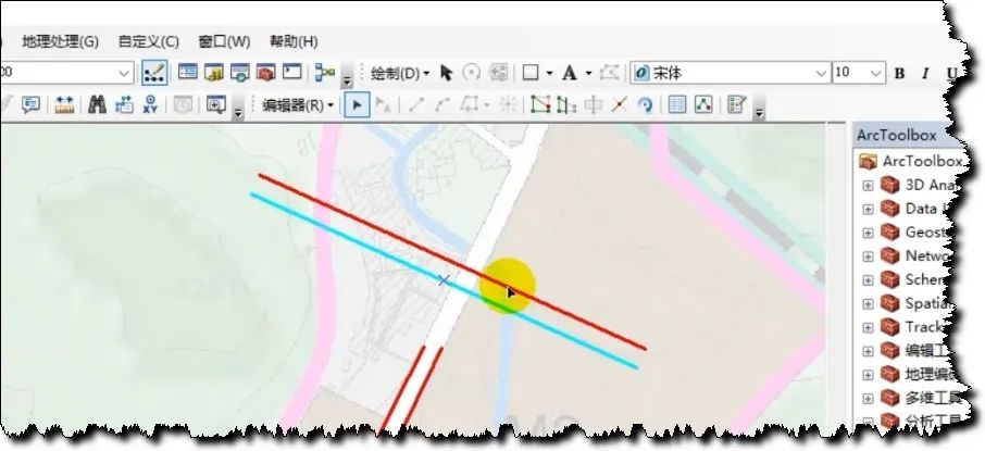
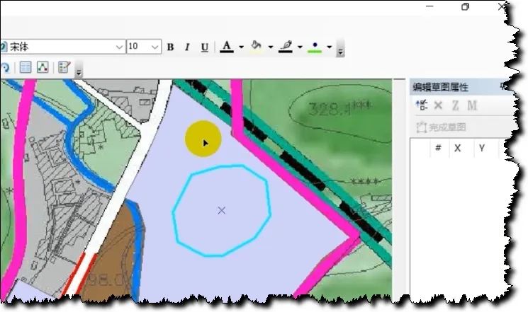
When we draw a picture, we often accidentally move a drawing spot (as shown below);
Then after I move the pattern, if I want to restore it exactly, it will be difficult to restore it to the original state. If I can't restore it, it will overlap each other or there will be gaps between the patterns. Many students may say, CTRL+Z, or the undo move in editing. In fact, sometimes when you move it many times, it is difficult to move it back;
So how do we restore it perfectly?
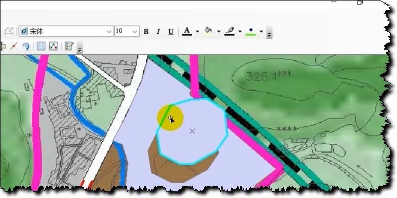
You can double-click this image spot to highlight its anchor point;
Then right-click on the anchor point;
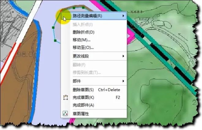
Click the Sketch Properties tool.
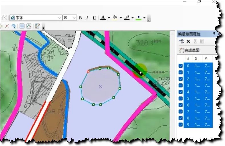
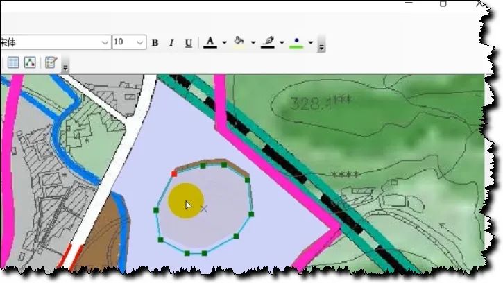
Select all these points, and then check the previous one. Select them all; then, put the mouse on one of the anchor points, then I just need to move this anchor point, and then the entire icon will move with it, and then it will snap to the position you want to correspond to.
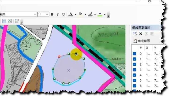
Release the mouse; now, it moves perfectly, come back and let’s take a look;
Question 2: Quickly fuse multiple point, line and surface data
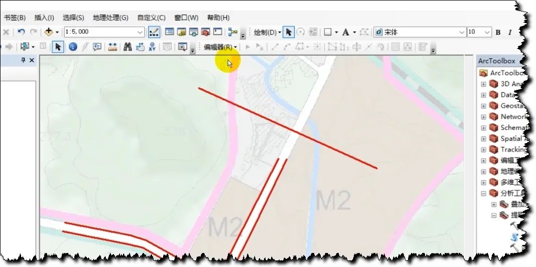
The road network below is composed of multiple lines, so what do I need now? I now need to merge these three lines into one. Some students may quickly think of fusion, right? Then fusion is indeed possible, but fusion requires it. There is an identical field in your attribute field. It will merge the same content into one data for you.
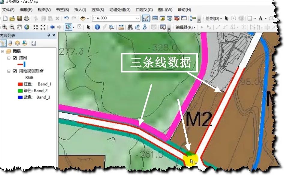
Then we have another, faster method, which is to use the editor to download and merge. Okay, let's take a look.
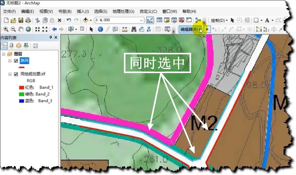
First select our three pieces of data;
After opening the editor, select the merge tool under the editor;

Click to select the target data to merge the three pieces of data into;
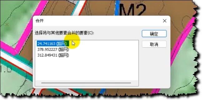
Click OK and it’s OK;
Question 3: How to offset the road network (line elements);
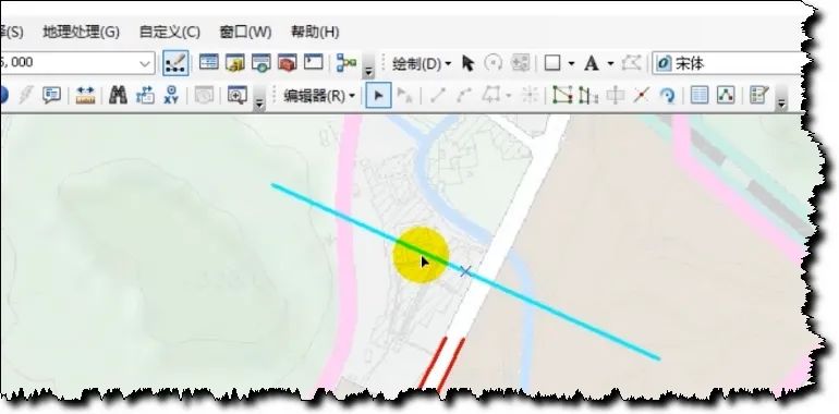
Suppose there is a road network line. Now, I want to draw the other side line of its network through offset method. This is a bit like CD offset, right?
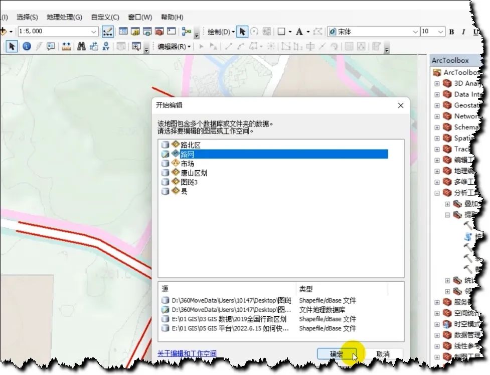
In fact, ArcGIS also has this function. Here, we open the editor, choose to start editing, and select the road network to be edited;
Then, we select the road network to be offset;
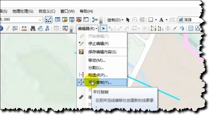
Under the editor, select this parallel copy.
We can choose the offset distance, let's say, we choose 23. Then the unit must be meters, because the units of our projected coordinate system are meters.
Then, the side type can be the left and right sides. As for the left and right sides, look at the direction of the line. This arrow points out the direction of the line for you. Let's say we offset 23 meters to the left. I'll choose the left side.
Then, this check will create a new feature for each selected line, which means that when this line is created, it will generate a new feature in the attribute table. Then click OK.
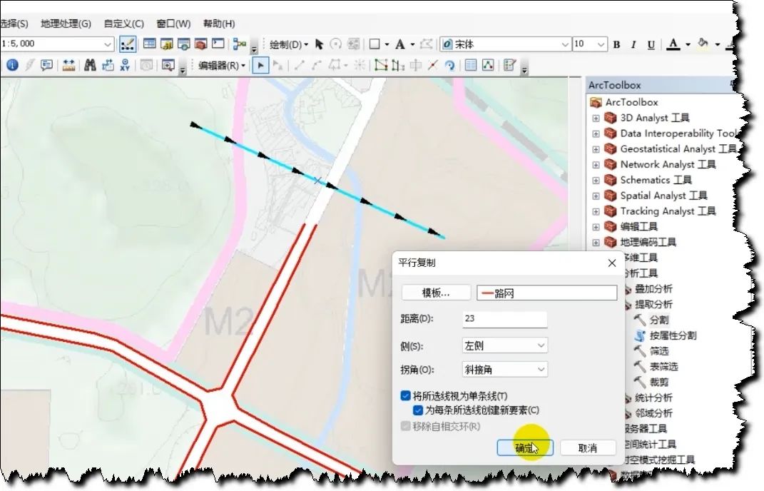
You see, it has offset a road network.