Table of contents
2. Elements included in component diagram
5. Component diagram representation method
1. Component diagram concept
Component Diagram (Component Diagram) is also called component diagram. It describes the software systemComply with and implement a set of interfaces that are physical and replaceableSoftware modules.
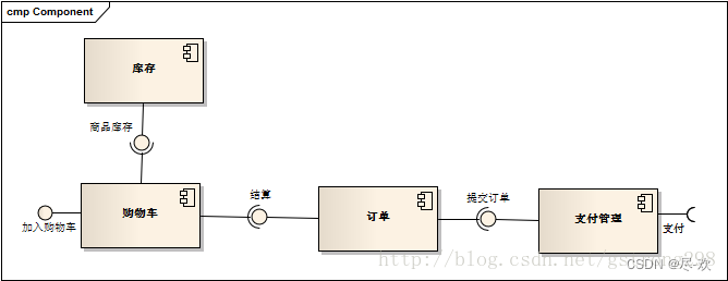
Component diagram = Component (Component) + Interface + Relationship + Port + Connector )
- Modeling the physical aspects of object-oriented systems uses two kinds of diagrams: components diagram and configuration diagram.
2. Elements included in component diagram
1. Component->Component
- Components are physical implementation units with well-defined interfaces and replaceable physical parts in the system.
- A component represents a physical implementation block of the system and represents a physical packaging of logical model elements such as classes, interfaces, collaborations, etc.
- A component exhibits behavior through its provided interface and request interface.
- Since in UML 2.0, a component is a class, it has properties, operations and visibility. The meaning of these concepts is the same as that defined in the class diagram, but here these concepts are applied to components.
Component naming:
There are two types of component names: simple names and path names. And corresponding extensions can be added according to the target operating system, such as java and dll.
Representation: The component is represented by a rectangle with two small rectangles protruding from the left side.
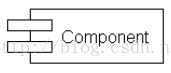
Representation method in UML2.0: The component is represented by a rectangular frame with the structure type "component" added, and the previous component symbol is added to the upper left corner. If there is no component details, you can add it in the center Just write the name.
(You can choose between the stereotype and the icon in the upper left corner)
UML2.0 divides components into basic components and packaging components
- Basic components
Focus on defining components as elements that are executable in the system. - Packaging components
extends the concept of basic components by focusing on defining a component as a set of related elements that are part of the development process. That is, the wrapper component defines the namespace aspect of the component. In a component's namespace, you can include classes, interfaces, components, packages, use cases, dependencies (such as mappings), and artifacts. According to this extension, components also have the following meaning: components can be used to assemble large-grained components by using the reused components as components of large-grained components and connecting their request and provision interfaces together (simple Understand: components contain components, and large components are assembled together).
Type of component
- Configuration component (Deployment Component): The components that need to be configured to run the system are the basis for forming the executable file - operating system, JAVA virtual machine, DBMS;
- Work Product Component: includes models, source code, and data files used to create configuration components. They are the source of configuration components—UML diagrams, Java classes, and database tables;
- Execution Component: A component created at runtime that is the allowed result of the final runnable system—.net component
2.Interface
- Interface An interface consists of a set of operations that specifies a contract that must be followed by components that implement and use the interface.
The interface is divided into providing interface and request interface
- The interface implemented by a component is called a provided interface (supplied interface), which means that the provided interface of a component provides services to other components. A component that implements an interface supports the characteristics possessed by the interface, including the constraints possessed by the interface.
- The interface used by a component is called the request interface (required interface), which is the interface that a component must follow when requesting services from other components.
Expression:
- The interface is represented by a "lollipop" graphic, which consists of a closed circle and a straight line.
- The required interface is represented by a "socket" graphic, which consists of a semicircle and a straight line.

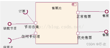
3. External interface - port
- Port is a concept introduced by UML2.0
- A port describes an explicit interaction point between a component and its environment and between a component and its internal components
- The port is an external window displayed by an encapsulated component. All interactions in and out of the component must pass through the port.
- Using ports can increase the encapsulation and substitutability of components to a greater extent.
- Ports are part of a component, and instances of ports are created and destroyed along with instances of the component to which they belong.
<1>The relationship between interfaces and ports
The provided interface describes the provision of services through ports, and the request interface describes the need to obtain services from other components through ports.
A component can communicate with another component through a specific port, and the communication is entirely described through the interface supported by the port.
<2>Expression
Normal interfaces are represented by a small box at the end, and the small box is called a port.
4. Connector - connector
UML2.0 provides two types of connectors:
- Delegation Connector - Delegation connector: connects the port of the external interface to the internal interface.
- Assembly Connector - Assembly connector: The component connector represents the relationship between components. It connects the classes inside the components and bundles the supply interface of a component with the required interface of a component.
- Connecting to a port means that the requesting port calls operations on the provided port to get service.
- The advantage of independent ports and interfaces is that during design, the two components do not need to know each other's internals, as long as their interfaces are compatible with each other.
- If one port provides a specific interface and another port requires this interface, and the interfaces are compatible, then the two ports - are connectable.
<1>Assemble connectors
There are two ways of representing assembly connectors:
- If you want to explicitly connect two component instances together, just draw a line between their ports.
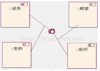
- If two component instances are connected because they have compatible interfaces, a "ball-and-hole" notation can be used to represent the connection relationship between the component instances.
An assembly connector is a connector between two component instances. It defines one component instance to provide services and another component instance to use these services. Assembly connectors are used to connect a requesting interface or port to a providing interface or port. At execution time, a message originates on a request port, travels along the connector, and is delivered to a providing port
<2>Delegated connector
Delegation has this meaning: a specific message flow will occur between the connected ports, possibly across multiple levels, and finally reach the final component instance to process the message. In this way, a hierarchical decomposition of component behavior can be modeled using delegated connectors.
The delegate connector distributes external requests to the component port to component instances inside the component for processing, or distributes requests from internal component instances to components outside the component through the component port.
A component inside a component can be another component or a class. Note that a delegate connector must be defined between two supply ports or two request ports.
Notes: Because components can be nested, the connection (ball-hole) between internal components is an assembly connector, and the connection between internal components and ports (solid arrow) is the delegate connector.
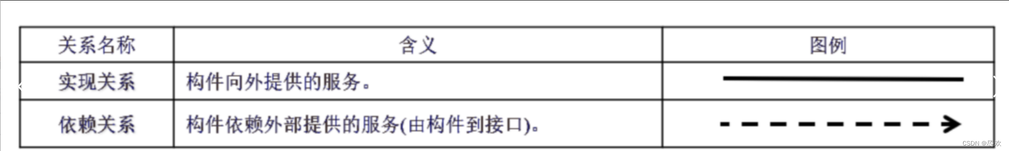
4.Relationship
5. Component diagram representation method


3. Examples