New Construction
Register mode
Damn it, I don’t want to try it when I see the name. Register creation should not be troublesome.
Forget it, just to learn the principles, I did it.
We try to write a register library function to reference.
First, we need to quote the st official startup file stmf4xx.s. The specific use will be explained in the following chapters. Then we create a new stm32f4xx.h file ourselves to map the registers. But if you just include this file into the project, the compilation will report an error:
.\Objects\led_reg.axf: Error: L6218E: Undefined symbol SystemInit (referred from startup_stm32f40xx.o).
After entering the startup file, you can see such a function:
; Reset handler
Reset_Handler    PROC
                 EXPORT  Reset_Handler             [WEAK]
        IMPORT  SystemInit
        IMPORT  __main

                 LDR     R0, =SystemInit
                 BLX     R0
                 LDR     R0, =__main
                 BX      R0
                 ENDP
The function of import is equivalent to extern, so the definition of this function is not found and we need to define it ourselves. This is why simply introducing the startup file will report an error.
And __main is when we define the main() function, the compiler will automatically link some functions defined by the c language library to initialize the stack and call our main().
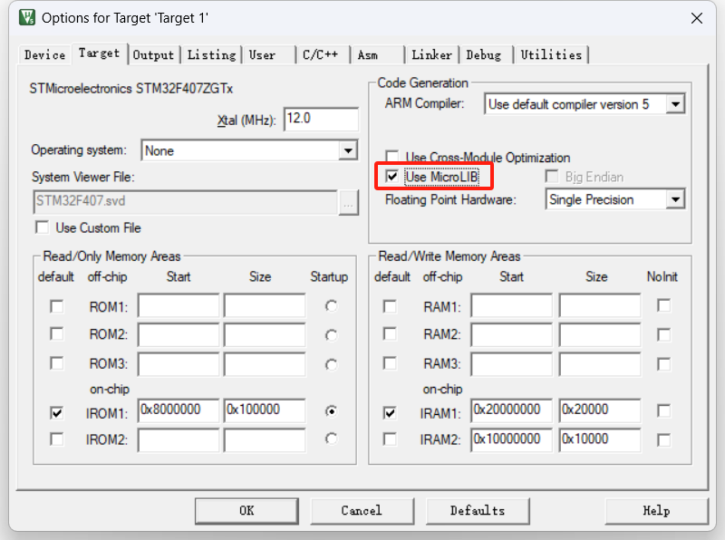
Note that if you want to generate the __main function, you must check the following item.
Wildfire, what you said is really good. I had hastily learned how to use the stm32 microcontroller before. During the competition, I wanted to transplant the code, but it didn't work even after changing the startup file. It just reported an error. It turned out to be this reason.
Then we only need to define such a function, it doesn't matter even if the content is empty.
Finally, the preliminary project framework we defined is as follows:
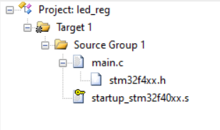
stm32f4xx.h: The content is empty, just have something like this.
main.c:
#include "stm32f4xx.h"

int main(){


	while(1){


	}
}

void SystemInit(){


}
Okay, this program can be burned into the board. There is no response after the burning is successful (because the program didn't do anything originally haha), but this is a big improvement.
Light up - 51 microcontroller version
The 51 microcontroller version refers to the reg51.h header file, in which the addresses of each pin are declared. We just need to assign values to the pins directly.
Calling code:
#include "reg51.h"

#ifdef 0
void main(){


	PA0=0xFE;
	while(1){

    }
}
#endif
Next we need to define the register location of the LED light. Read the schematic below:
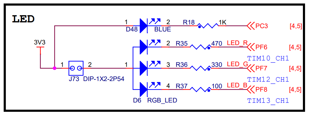
As you can roughly see, the RGB LED on the board controls RGB brightness through three pins. When the output is low, it turns on and lights up.
The specific output method is through ODR. To find the stm32f4xx Chinese reference manual, you can see:
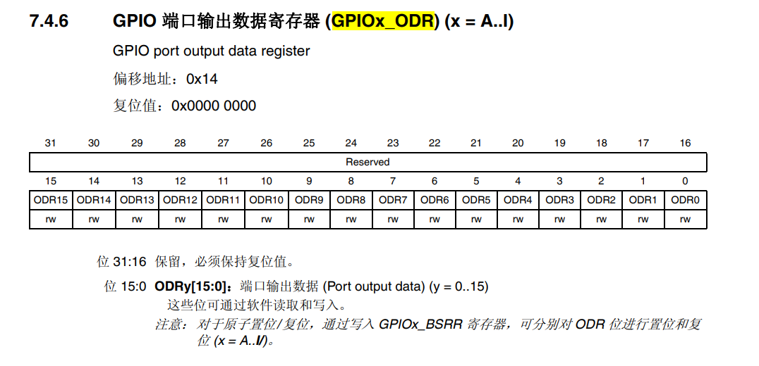
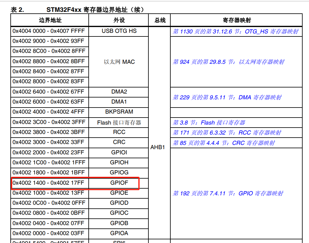
Then we have to assign values to the addresses of 0x4002 1400 +14, and assign the bits 1<<6 1<<7 1<<8 to low level respectively.
int main(){


	 *(unsigned int *)(0x40021400+14)&=~(1<<6);
	while(1){


	}
}
However, it doesn't light up either. It's weird if it lights up. The stm32 register needs to be initialized and configured first.
Lights on—stm32 version
First we need to set the GPIO mode.
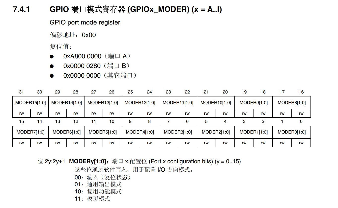
If you want to light a lamp, it outputs high and low levels, which is the 01 general output mode.
*(unsigned int *)(0x40021400+0)&=~(3<<(6*2));
*(unsigned int *)(0x40021400+0)|=(1<<(6*2));
It means to first set the PF6 mode position to 00, and then assign it to 01 general output.
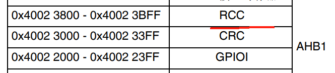
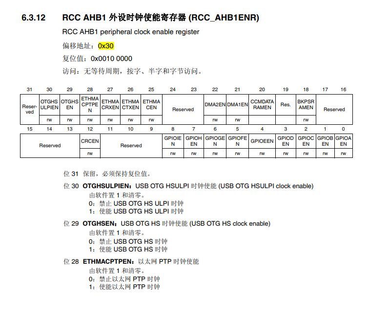
After configuring the mode, you also need to configure the clock. Each peripheral of stm32 needs to configure the clock.
As mentioned earlier, the GPIO is in AHB1.
The entire code is as follows:
#include "stm32f4xx.h"

int main(){


    //RCC
    *(unsigned int *)(0x40023800+0x30)|=(1<<5);

    //Mode
    *(unsigned int *)(0x40021400+0)&=~(3<<(6*2));
    *(unsigned int *)(0x40021400+0)|=(1<<(6*2));


    *(unsigned int *)(0x40021400+0x14)&=~(1<<6);
    while(1){


	}
}

void SystemInit(){


}
Next, we extract these address values and define the macro mapping registers.
//stm32f4xx.h
/* 用来存放寄存器映射相关的代码 */
#define RCC_AHB1_ENR    *(unsigned int *)(0x40023800+0x30)
#define GPIOF_MODER     *(unsigned int *)(0x40021400+0)
#define GPIOF_ODR       *(unsigned int *)(0x40021400+0x14)

//main.c
#include "stm32f4xx.h"

int main(){


    //RCC
    RCC_AHB1_ENR|=(1<<5);

    //Mode
    GPIOF_MODER&=~(3<<(6*2));
    GPIOF_MODER|=(1<<(6*2));


    GPIOF_ODR&=~(1<<6);
    while(1){


	}
}

void SystemInit(){


}
Light up - the running water lamp flashes
Use software delay to achieve RGB running water light flashing. It's very simple. We have already looked at the 3 LED channel PF678.
#include "stm32f4xx.h"

void delay_ms(int time);

int main(){


    //RCC
    RCC_AHB1_ENR|=(1<<5);

    //Mode
    GPIOF_MODER&=~(3<<(6*2));
    GPIOF_MODER|=(1<<(6*2));
    GPIOF_MODER&=~(3<<(7*2));
    GPIOF_MODER|=(1<<(7*2));
    GPIOF_MODER&=~(3<<(8*2));
    GPIOF_MODER|=(1<<(8*2));

    while(1){


        GPIOF_ODR|=(7<<6);
        GPIOF_ODR&=~(1<<6);
        delay_ms(1000);
        GPIOF_ODR|=(7<<6);
        GPIOF_ODR&=~(1<<7);
        delay_ms(1000);
        GPIOF_ODR|=(7<<6);
        GPIOF_ODR&=~(1<<8);
        delay_ms(1000);
	}
}

void SystemInit(){


}

//毫秒级的延时
void delay_ms(int time)
{


   int i=0;
   while(time--)
   {


      i=4000;
      while(i--) ;
   }
}
Light up - GPIO specific function block diagram correspondence
GPIO: General purpose input and output pin. We can output or read data through programming. Most GPIOs have already been connected and have some functions defined (such as the PF6 LED tried above), and some pins have multiple functions that support remapping.
STM32 GPIO except adc is 3.3v, other GPIO are 5v tolerant.
GPIO frame (focus) below:
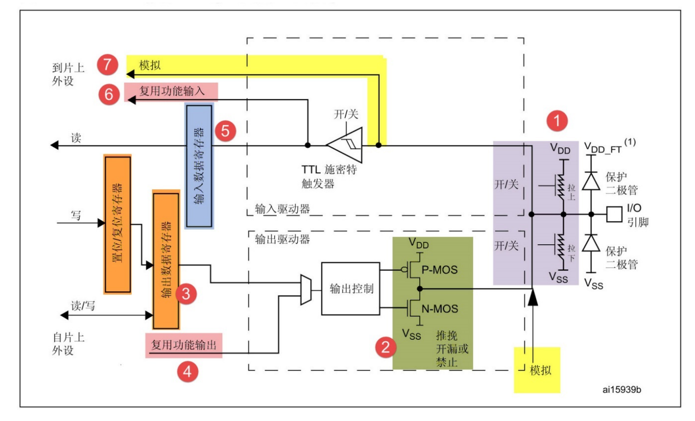
Let’s start with the output. The rightmost IO pin is one of 144 pins connected in a circle around the chip. Except for the IO pins, everything else in this picture is packaged inside the chip and we can't see it.
There are two protection diodes to the left. When the voltage is greater than 5V, the current will go up VDD_FT. When the voltage is negative, current will flow from VSS to the IO pin.
Pull-up and pull-down resistors: If we connect an external device that works at a low level, but we don't want the peripheral to work as soon as it is powered on, we can set a pull-up resistor to stabilize it for a period of time.
GPIO output data source: reset register BSRR, or ODR setting (3 lower part in the figure). The high 16 bits of the reset register are reset (write 1 to set 0) and the low 16 bits are set (write 1 to set 1), and the setting priority is higher.
Configure the GPIO mode (input/output, which channel to choose) through the MODER configuration used previously.
The output mode (output control part in the figure) configures the port output type register OTYPER, such as push-pull output and open-drain output.
Push-pull output: It has direct drive capability, outputting 0 means low level, and outputting 1 means outputting high level that can work. The principle is to use an amplification circuit?
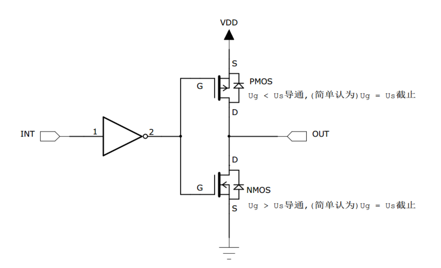
When the input (INT) is high level, the PMOS turns on after reverse direction and outputs high level. When the input is low level, the NMOS turns on after reverse direction and outputs low level. We can use a small current to drive a large current.
Open-drain output: It has no means of outputting high level. The low level can be connected to ground, and the high level has no PMOS tube and is in a floating state. An external resistor is required.
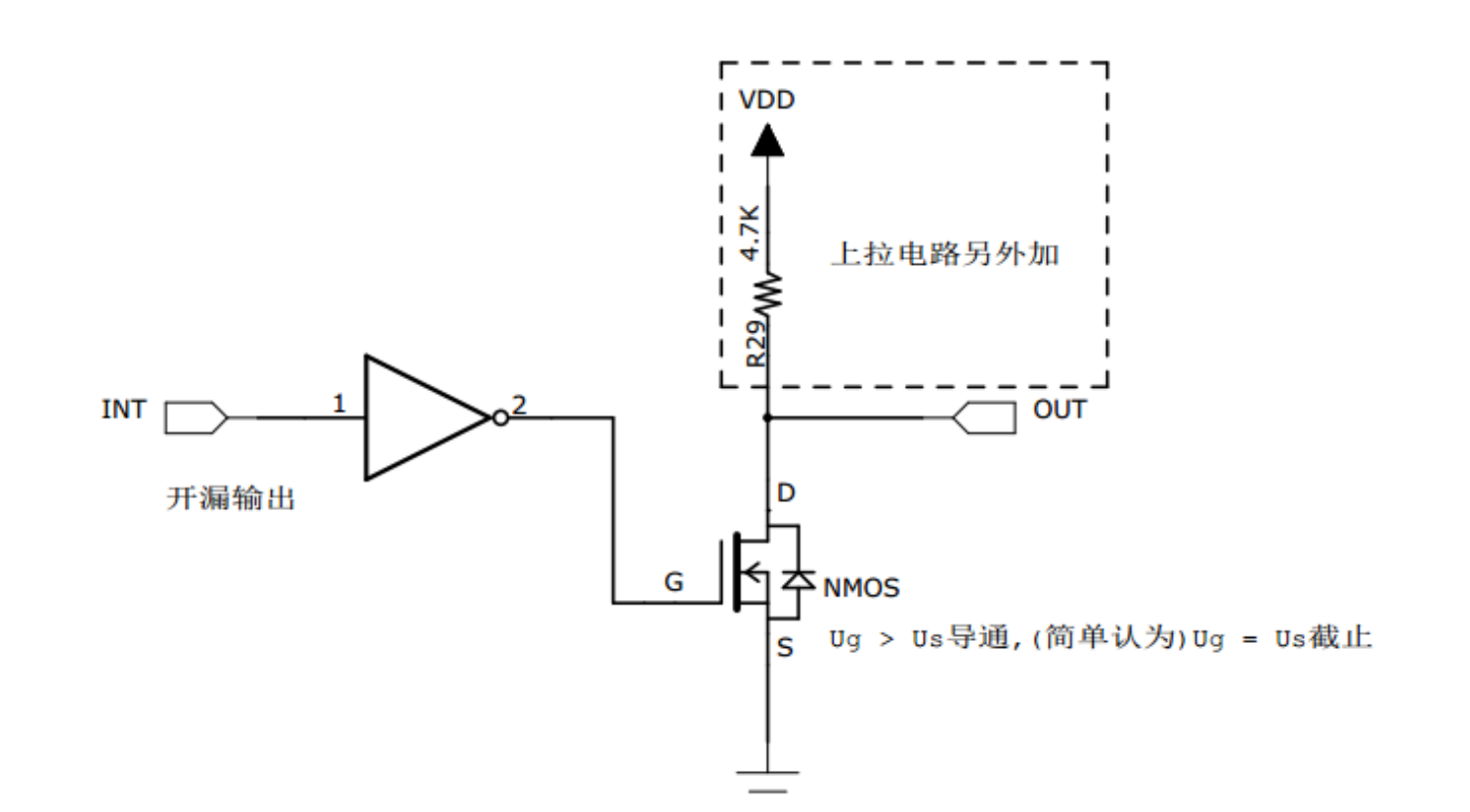
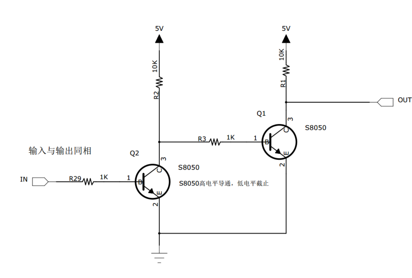
The way stm32 outputs 5V voltage is to use an open-drain output external resistor. Reverse by connecting two transistors.
The input and output of the analog part in the block diagram do not need to be configured with these mode information. The peripherals are directly connected to the protection diodes and then to the output pins.
After the input part in the block diagram passes the protection voltage, the Schmitt trigger needs to be adjusted. For example, if the original voltage value is not exactly 0 or 3.3V, the Schmitt trigger treats everything above 1.8V as 1, and everything below as 0 before inputting it into the chip. The simulation part does not need to go through the Schmitt trigger.
So the steps to configure the GPIO output are as follows:
- GPIO function, general output, multiplexing function, analog input, etc. MODER;
- Output push-pull or open-drain OTYPER;
- Output speed OSPEEDR;
- Whether the pull-up and pull-down resistors need to be turned on PUPDR;
- Specific output content BSRR or ODR.
Enter the experiment introduction after the input part~
Re-string the code according to the entire process, as follows: (In fact, it is almost the same as before, just follow the process again)
/* 用来存放寄存器映射相关的代码 */
#define RCC_BASE    (unsigned int *)    0x40023800
#define GPIOF_BASE  (unsigned int *)    0x40021400

#define RCC_AHB1ENR         *(RCC_BASE+0x30)

#define GPIOF_MODER         *(GPIOF_BASE+0x00)
#define GPIOF_OSPEEDR       *(GPIOF_BASE+0x08)
#define GPIOF_PUPDR         *(GPIOF_BASE+0x0C)
#define GPIOF_ODR           *(GPIOF_BASE+0x14)
#define GPIOF_BSRR          *(GPIOF_BASE+0x18)

//main.c
#include "stm32f4xx.h"

int main()
{


    RCC_AHB1ENR |= (1<<5);
    GPIOF_MODER &= ~(3<<(6*2));
    GPIOF_MODER |= (1<<(6*2));
    while (1)
    {


    }
}

void SystemInit()
{


}
Remember to check before burning: use MicroLib.