1 What is ROS's TF coordinate transformation TransForm Frame
In the robot system, it is equipped with a variety of sensors, such as lidar and cameras. These sensors can sense the position of objects around the robot, including coordinates, lateral, longitudinal and height distance information. Their role is to assist the robot in accurately locating obstacles. However, not all sensors can directly provide information about the orientation of an object relative to the robotic system or other components. While it is possible to obtain information about an object's orientation relative to a specific sensor, this is not equivalent to information about the object's orientation relative to the entire robotic system or other components. There are limitations in the display of information, as this requires a certain conversion process. This is described in more detail below:
Scenario 1: Radar and Car There is a mobile robot chassis, and a radar is installed on the chassis. The offset of the radar relative to the chassis is known. Now the radar detects an obstacle information, and the obtained coordinates are (x, y). ,z), this coordinate is based on the radar as the reference system. How to convert this coordinate into the coordinates with the car as the reference system?
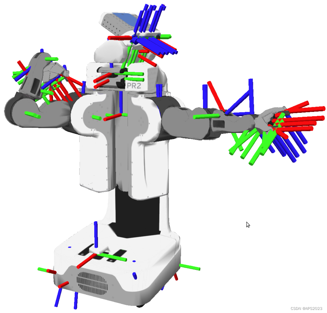
Scenario 2: An existing robot with a robotic arm (for example: PR2) needs to grip a target object. The current robot head camera can detect the coordinates (x, y, z) of the target object, but the coordinates are based on the camera as the reference system. , and the actual operation of the target object is the gripper of the robotic arm. Currently we need to convert the coordinates into coordinates relative to the gripper of the robotic arm. How to achieve this process?
According to the knowledge we learned in high school, after clarifying the relative relationship between different coordinate systems, we can realize the conversion of any coordinate point between different coordinate systems. However, this calculation implementation is more commonly used, and the algorithm is also a bit complicated. Therefore, the relevant module is directly encapsulated in ROS: coordinate transformation (TF).
If an object is calibrated through the coordinate system in ROS, it will be calibrated through the right-hand coordinate system.
Used in ROS to realize the conversion of points or vectors between different coordinate systems.
In ROS, coordinate transformation originally corresponded to tf. However, starting from the hydro version, tf was abandoned and migrated to tf2. The latter is more concise and efficient. The common function packages corresponding to tf2 are:
tf2_geometry_msgs: ROS messages can be converted into tf2 messages.
tf2: Encapsulates common messages for coordinate transformation.
tf2_ros: Provides roscpp and rospy bindings for tf2, encapsulating commonly used APIs for coordinate transformation.
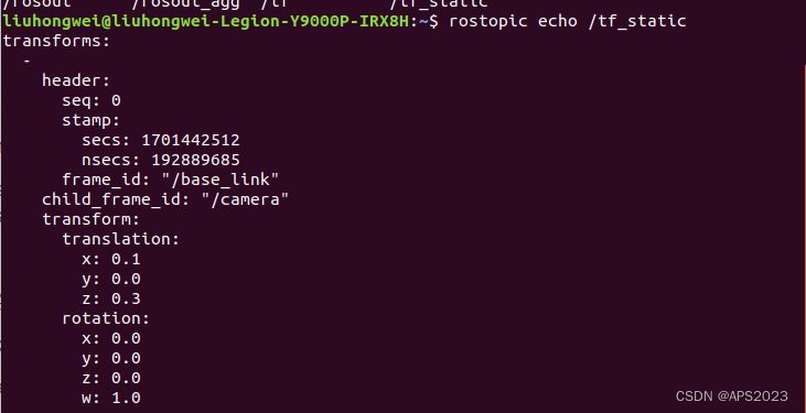
2 msg information of coordinate transformationgeometry_msgs/TransformStamped与geometry_msgs/PointStamped
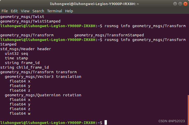
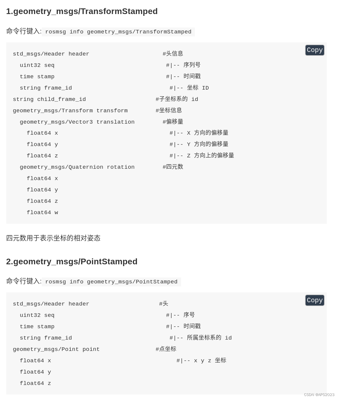
The commonly used msg in coordinate changes aregeometry_msgs/TransformStamped and geometry_msgs/PointStamped。我们可以打开终端用rosmsg info查看:
Here frame_id is the referenced coordinate system, child_frame_id is another coordinate system, and transform is the offset of child_frame_id relative to frame_id.
The frame_id here refers to which coordinate system my coordinate point is based on. xyz is the value of the coordinate point
The former is used to transmit position information related to the coordinate system, and the latter is used to transmit information about coordinate points in a certain coordinate system. In coordinate transformation, the relative relationship of the coordinate system and the coordinate point information are frequently used.
3 Static coordinate transformation
The so-called static coordinate transformation means that the relative position between the two coordinate systems is fixed.
For example, there is no conversion between the camera and radar in our handheld scanning equipment.
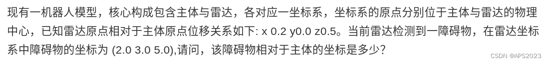
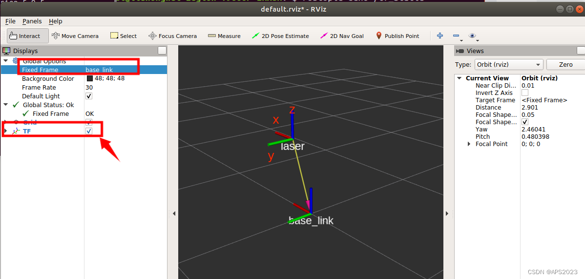
There is a robot model whose core components includemain body and radar, each corresponding to a coordinate system. The origins of the coordinate system are respectively located at the main body and radar. The physical center of the radar, the known displacement relationship between the radar origin and the body origin is as follows: x 0.2 y0.0 z0.5. The radar currently detects an obstacle. The coordinates of the obstacle in the radar coordinate system are (2.0 3.0 5.0). What are the coordinates of the obstacle relative to the subject?
Implementation analysis:
The relative relationship between coordinate systems can be published through the publisher
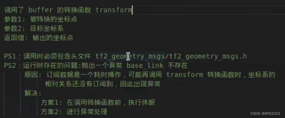
The subscriber subscribes to the relative relationship of the published coordinate system, then passes in the coordinate point information (can be hard-coded), then implements coordinate transformation with the help of tf, and outputs the result
Implementation process:
Create a new function package and add dependencies
Writing the publisher implementation
Write subscriber implementation
Execute and view the results
Here we use clion to implement it.
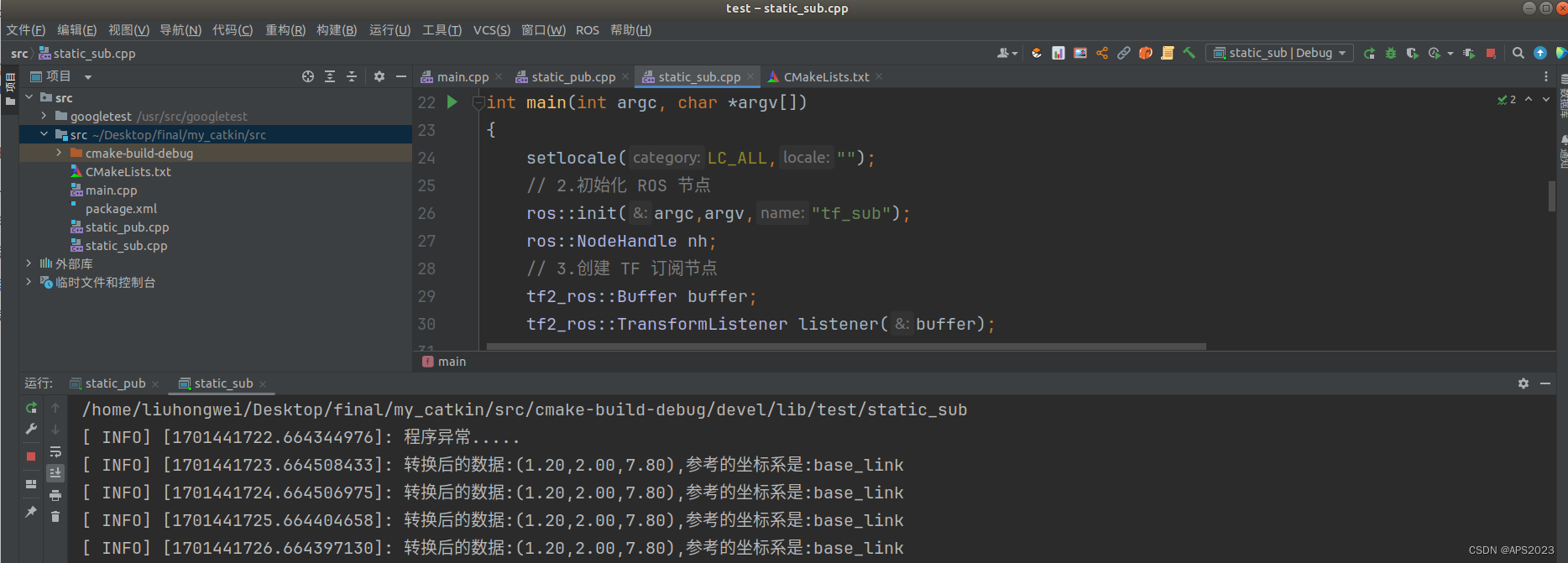
3.1 C++ clion implements static coordinate transformation
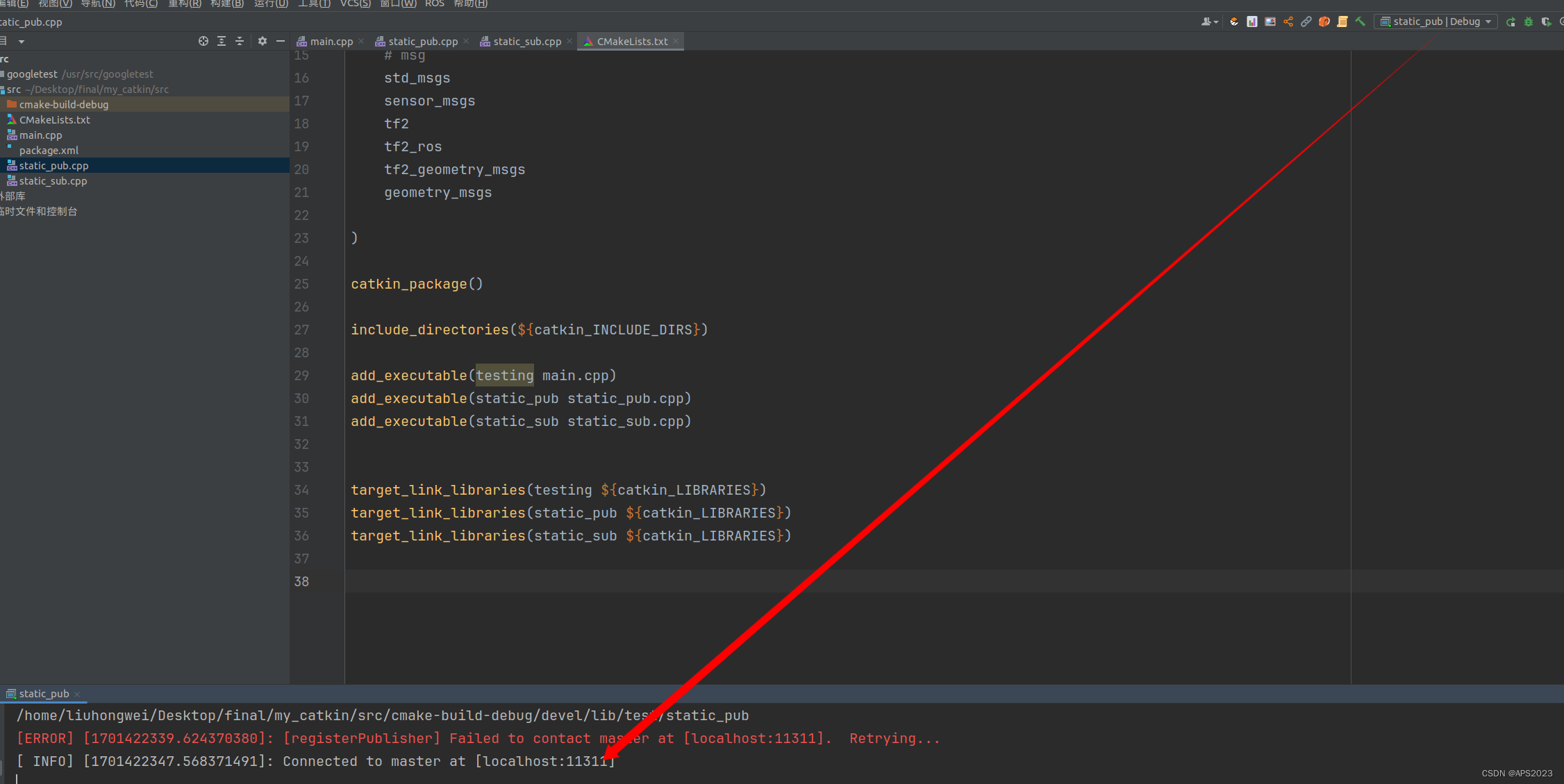
3.1.1 CMakeLists.txt configuration
Creating project function packages depends on tf2, tf2_ros, tf2_geometry_msgs, roscpp rospy std_msgs geometry_msgs.
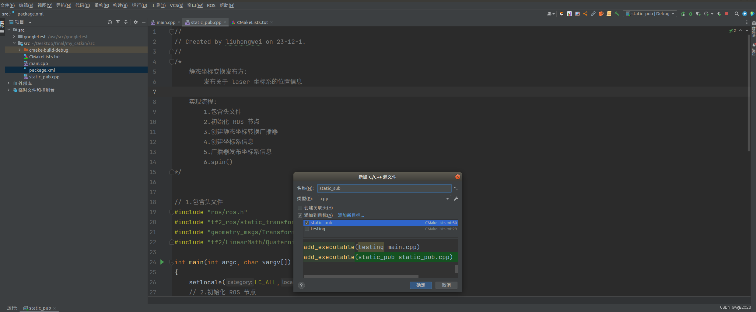
Static coordinate transformation publisher:
    Publish location information about the laser coordinate system

Implementation process:
    1. Include header files
    2. Initialize ROS nodes
    3. Create a static coordinate transformation broadcaster
    4. Create coordinate system information
    5. The broadcaster publishes coordinate system information
    6.spin()
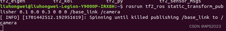
When the relative position between coordinate systems is fixed, then the required parameters are also fixed: parent coordinate name, child coordinate system name, x offset, y offset, z offset, x roll angle, y pitch Angle, z-yaw angle, the implementation logic is the same, but the parameters are different, then the ROS system has encapsulated special nodes, and the usage is as follows: