I just recently learned about Shader Graph water flow. Let’s take a look at other implementation methods and record them.
1 What is flow map
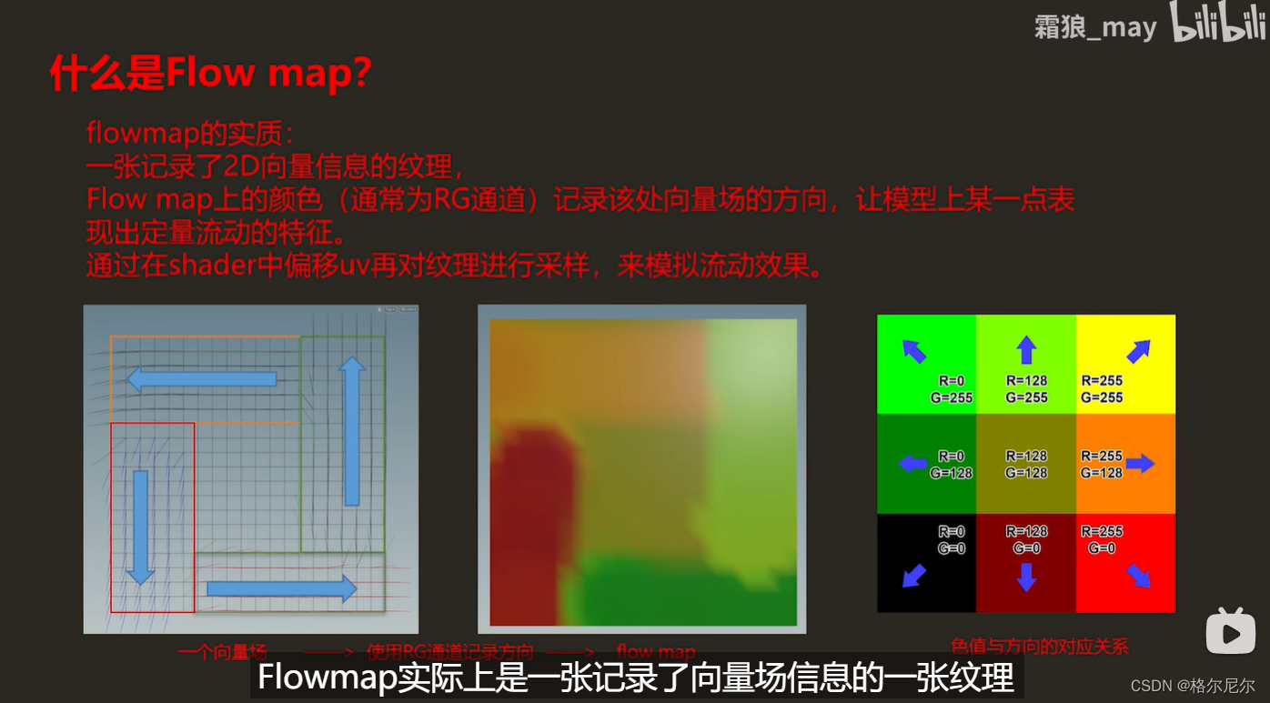
1 What is a flow map?
The essence of flowmap: the color on a texture flow map that records 2D vector information (usually the RG channel) records the direction of the vector field there, allowing a certain point on the model to show the characteristics of quantitative flow. Simulate the flow effect by offsetting the UV in the shader and then sampling the texture.
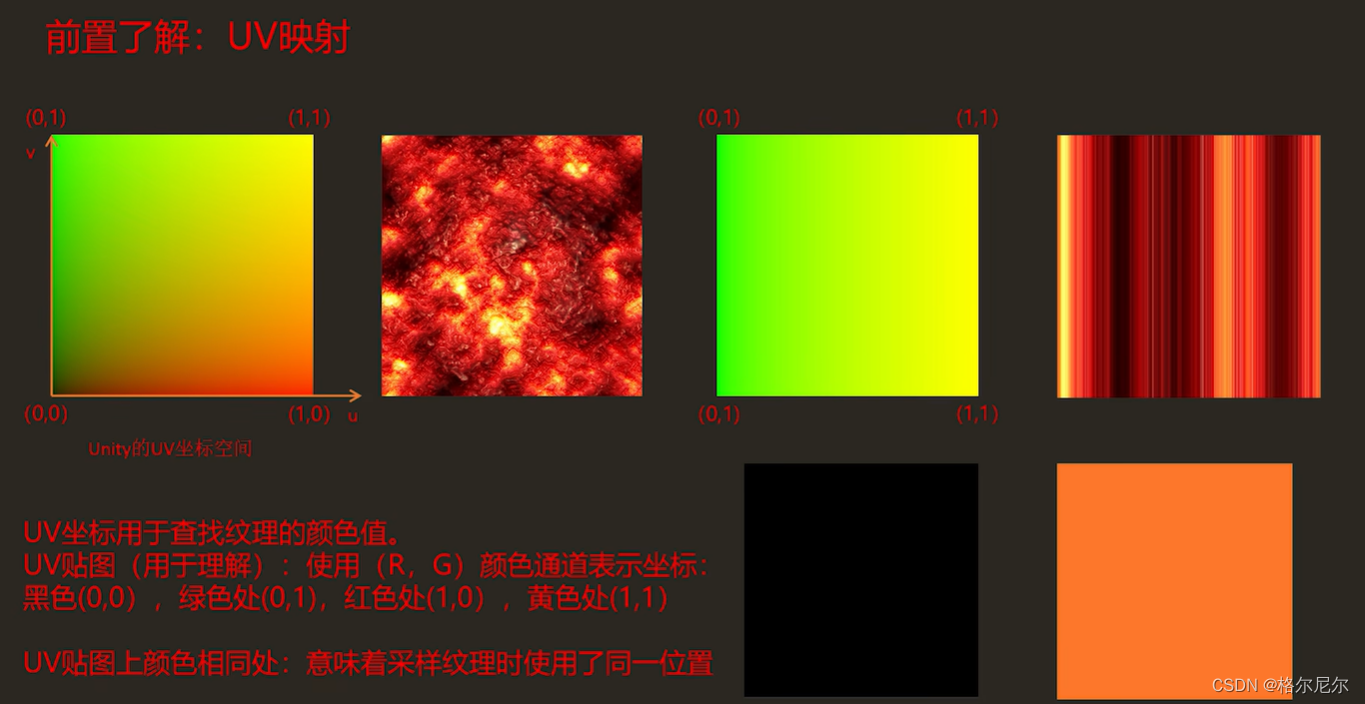
2 Texture mapping, the left side is the UV coordinate value, and the right side is the sampling result
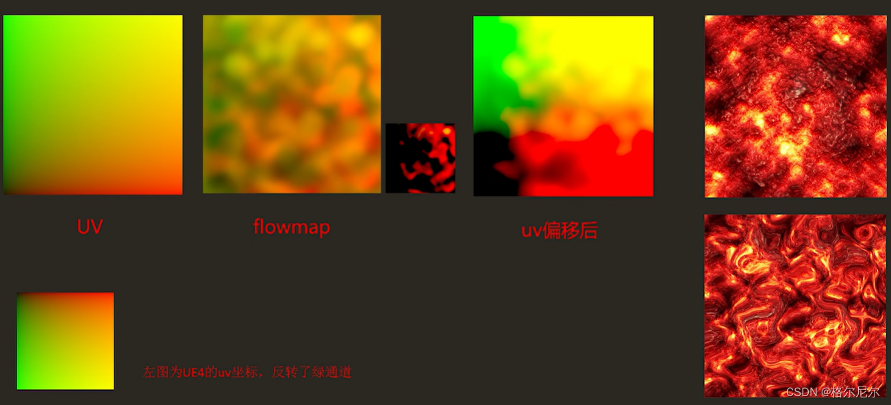
UV uses flow map offset to produce different effects
Why use flowmap?
Similar to UV animation, not vertex animation. In other words, there is no need to operate the model vertices, and it is easy to achieve low computational overhead.
Not just water surfaces, any flow-related effects can use flowmap.
The principle of flowmap : the uv is offset by the vector field information it carries, to interfere with the process when we sample. As you can see in the figure, after the flowmap is offset, the original normal sampling becomes a distorted effect.
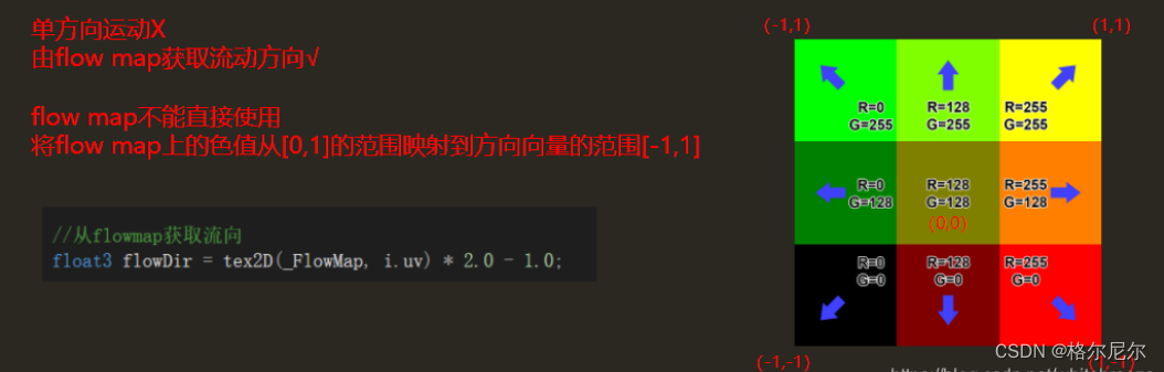
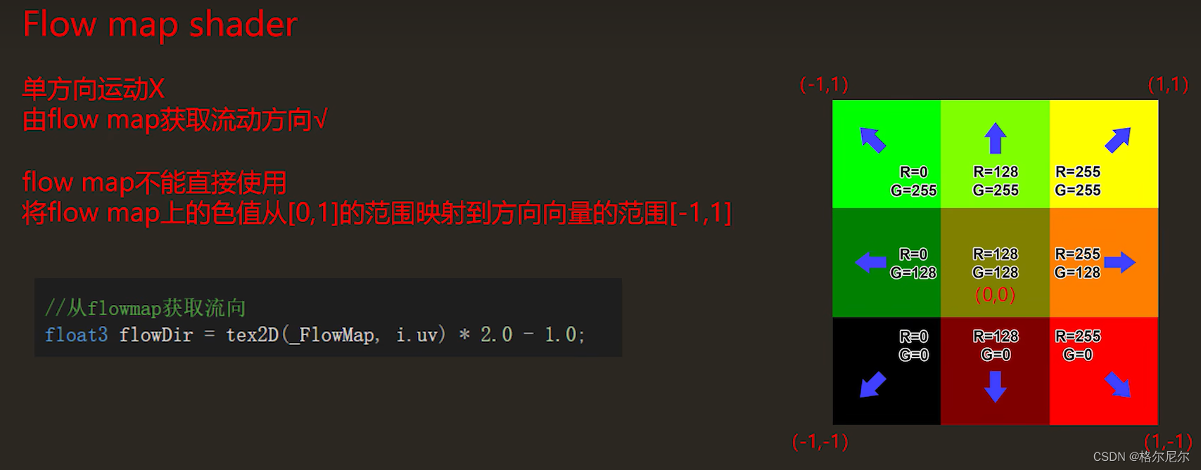
We need a better direction of movement. The correct way is to obtain the flow direction from flowMap. However, the flow map cannot be used directly. The color value on the flow map needs to be mapped from the range of [0,1] to the range of the direction vector [- 1.1].

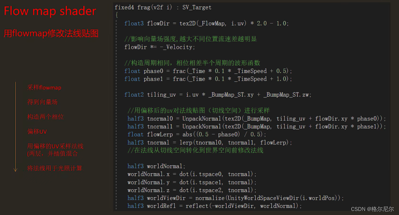
2 flow map Shader
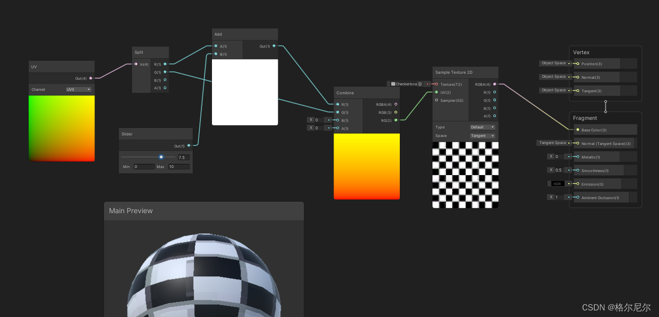
Use Shader Graph to understand Flow map
1. Sampling Flow map to obtain vector field information
2. Use vector field information to make the UV of the map sample change with time
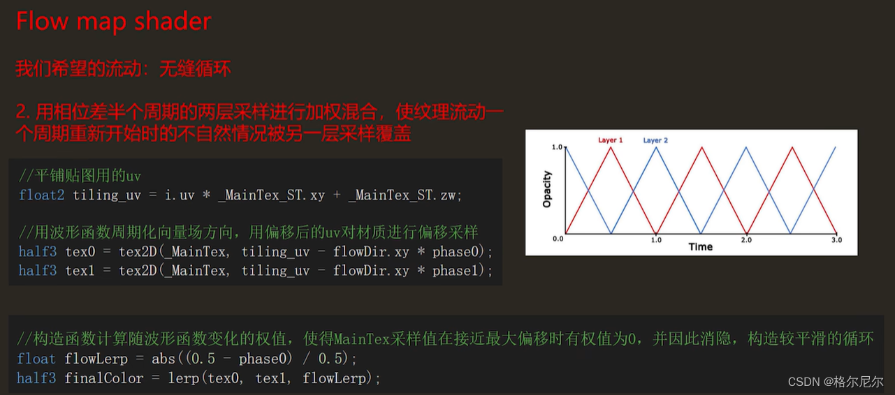
3. Collect the same map twice with a half-cycle phase difference and linearly interpolate , making the texture flow continuously
A function simulation website https://www.desmos.com/calculator?lang=zh-CN is used here.
The simplest offset with time? Why is
time
subtracted?
Let’s first look at the situation of uv+time uv) + (time.0): a certain point on the model: as time increases, the farther the sampled pixels are
Visually it can be described as: pixels further away are shifted towards this point, and the visual effect is opposite to the algorithm we intuitively recognize. The UV value
is a vector (u, v), and naturally follows the vector algorithm. But When UV is offset, what changes is not the position of the vertices.
https://teckartist.com/?page_id=107 Click to download the manifold diagram drawing tool
As time progresses, the deformation becomes more and more exaggerated, and the offset needs to be controlled within a certain range to achieve seamless circulation.
According to the principle of Flowmap, if we want to create a flow effect, we need uv to shift periodically with time.
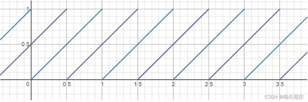
Since it is a periodic shift, time must have a threshold. The first thing people think of when there is a threshold for a period is the frac() function.
But there is a problem with the frac() function, that is, there are gaps in the period.
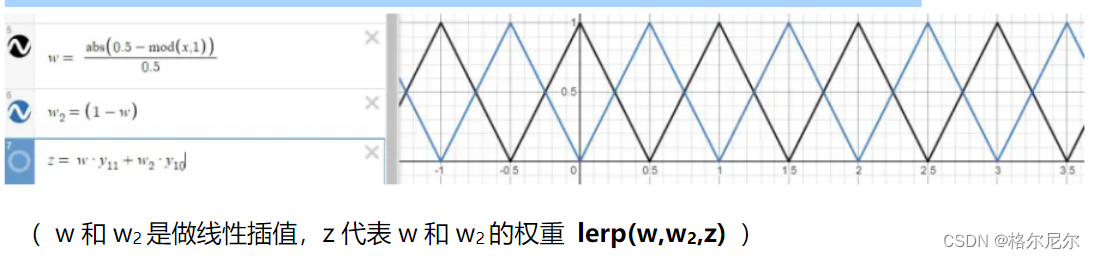
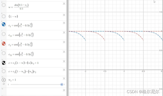
People want to remove the faults that cycle from 0.99 to 1. At this time, a smart person thought of a weighted average. Use two lines with periods and regular changes, blue and purple. The weighting is constantly transformed to make the fault effect disappear. When x=0.5, the blue line weights 1, and the purple line weights 0. When x=1, the blue line weights 0, and the purple line weights 1. So how do you make x fluctuate linearly at 0 1 0 in period 0
~ 1 ? Someone gave me the formula.
Some people will think of sin and cos + some changes to replace the above formula. This is not easy to use because the input is radians and π is an irrational number. You cannot accurately control the period of sin and cos. Use /3.1415926. This form of operation also wastes GPU instructions. As time goes by, the error will become larger and larger.
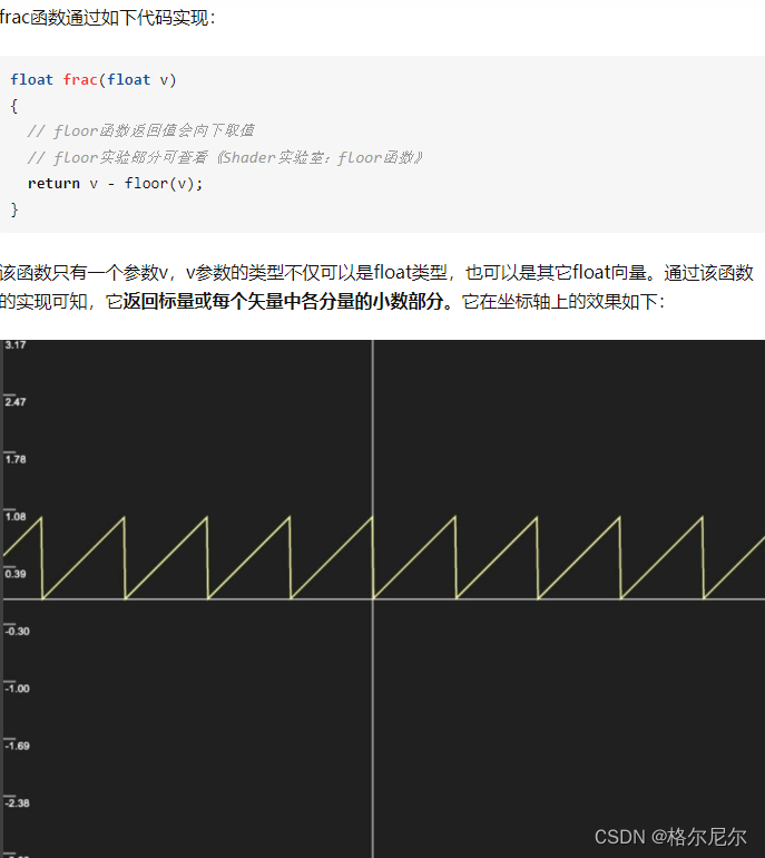
3 Shader implementation
The role of frac function
Shader "MyShader/Water"
{


    Properties
    {


        // basecolor
        _MainTex ("Texture", 2D) = "white" {

    }
        //混色
        _Color("Tint", Color) = (1,1,1,0.5)
        //水体法线
        _MainTex ("Texture", 2D) = "white" {

    }
        _FlowMap("FlowMap", 2D) = "white" {

    }
        //向量场强度
        _FlowSpeed("intensity", float) = 0.1
        //采样速度
        _TimeSpeed("speed", float)= 1
        //创建开关
        [Toggle]_reverse_flow("reverse", Int) = 0
    }
    SubShader
    {


        Tags {


                "RenderType"="Opaque"
                "IgnoreProjector" = "True"
        }
        Cull Off
        Lighting Off
        ZWrite On
        LOD 100

        Pass
        {


            CGPROGRAM
            #pragma vertex vert
            #pragma fragment frag
            #pragma shader_feature _REVERSE_FLOW_ON

            #include "UnityCG.cginc"

            struct a2v
            {


                float4 pos : POSITION;
                float2 uv : TEXCOORD0;
            };

            struct v2f
            {


                float2 uv : TEXCOORD0;
                UNITY_FOG_COORDS(1)
                float4 pos : SV_POSITION;
            };

            fixed4 _Color;
            sampler2D _MainTex;
            sampler2D _FlowMap;
            float4 _MainTex_ST;
            float _FlowSpeed;
            float _TimeSpeed;

            v2f vert (a2v v)
            {


                v2f o;
                //顶点坐标
                o.pos = UnityObjectToClipPos(v.pos);
                //顶点UV
                o.uv = v.uv;
                return o;
            }

            fixed4 frag (v2f i) : SV_Target
            {


                //0~1 *2-1 得到 -1~1 方向
                fixed4 flowDir = tex2D(_FlowMap, i.uv) * 2.0 - 1.0;
                //强度修正
                flowDir *= _FlowSpeed;
                //正负修正
                #ifdef _REVERSE_FLOW_ON
                    flowDir *= -1;
                #endif

                //两个0~1循环 计时
                float phase0 = frac(_Time * 0.1 * _TimeSpeed);
                float phase1 = frac(_Time * 0.1 * _TimeSpeed + 0.5);

                float2 tiling_uv = i.uv * _MainTex_ST.xy +   _MainTex_ST.zw;

                half3 tex0 = tex2D(_MainTex, tiling_uv + flowDir.xy * phase0);
                half3 tex1 = tex2D(_MainTex, tiling_uv + flowDir.xy * phase1);

                float flowLerp = abs((0.5 - phase0) / 0.5);
                half3 finalColor = lerp(tex0, tex1, flowLerp);
                return float4(finalColor, 1.0) * _Color;
            }
            ENDCG
        }
    }
}
I want to try it and add that the code in the NormalMap video is incomplete and uses TBN vectors to calculate world space normals. I will add it later.