1. Rendering pipeline and model basics
1. Programmable rendering pipeline
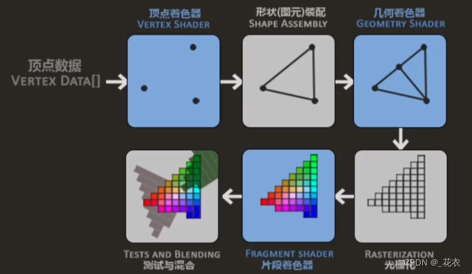
● Blue background: Programmable pipeline
● Vertex shader: Calculates the vertices of the model
● Fragment shader: Calculates the interpolated information in the rasterization stage
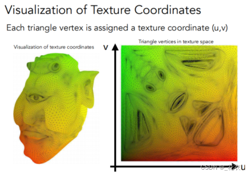
2.uv
● Texture mapping: The surface of any 3D object is 2D → Texture is a picture → Texture mapping: Cover this picture on a 3D object ● UV is to
expand this picture in a coordinate system, with coordinate axes For u and v
● Each vertex can use uv coordinates to obtain the information stored in the texture
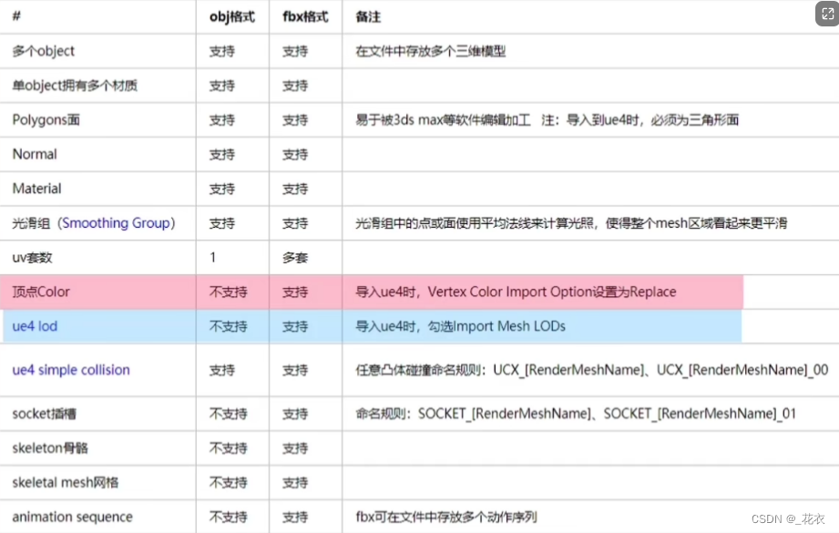
obj and fbx format comparison
2. Material Basics
1. Diffuse reflection
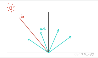
● Light is reflected in all directions.
● Supplement:
○ (GAMES101) The incident Radiance is uniform → The incident and exiting Radiance are equal, and their Radiances are both uniform → The incident Radiance and the exiting Radiance are equal ● The Lambert model simply considers that
all directions are uniform
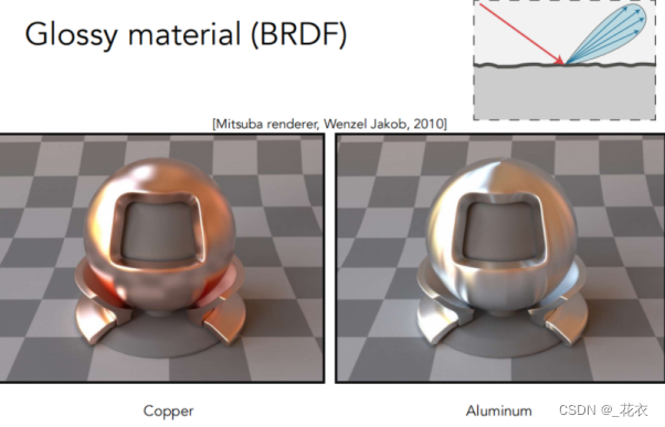
2.Specular reflection
smooth specular reflection
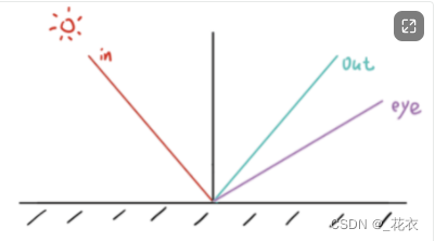
● Incidence is equal to emission
● The incident light is reflected according to the surface normal, and has energy only in the reflection direction, and is 0 in other directions.
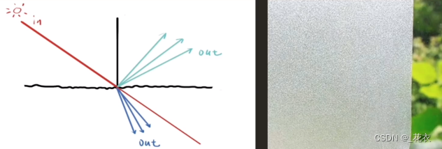
Rough specular reflection
● The normal offset is relatively small, so the reflection is concentrated in one area, giving it a frosted texture.
3.Refraction
● For special media, in addition to reflection, refraction will also occur
● Among them, the energy of reflection and refraction is determined by Fresnel's law:
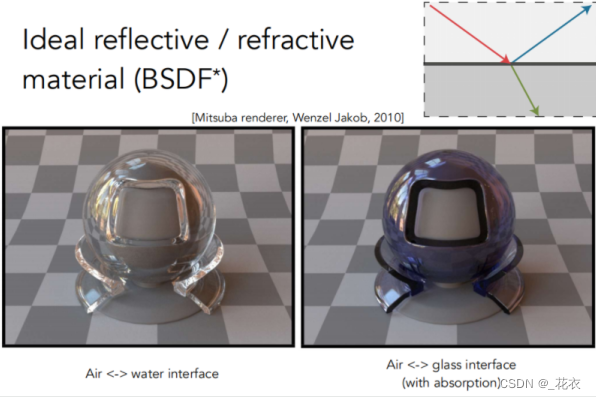
rough specular refraction
Similar to rough specular reflection, it is also concentrated in one area.
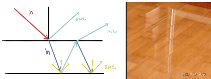
4 multi-layer materials
● In addition to the material of the object itself, there is something on the surface (you can see the material itself and a layer of the surface)
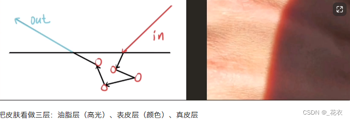
5. Subsurface scattering/3S (BSSRDF)
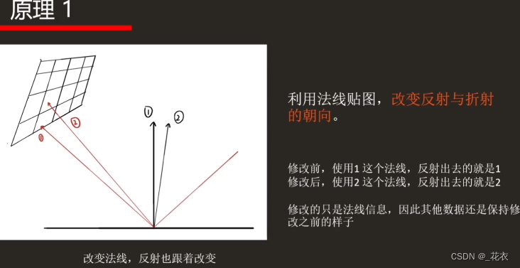
6. Change the material surface
● There is no perfectly smooth surface in the real world, and the normals at the vertices of the model are also limited, so we can use normal maps to create effects ●
Normals are involved in lighting calculations, so we can adjust the normals to Adjust the corresponding lighting calculation
○ For example, in the card rendering of "Guilty Gear", break the normal line by hand
● Supplement: (GAMES101): In the rendering equation, one item related to the material: BRDF In CG, Material==BRDF
3. Model data analysis (role in rendering pipeline)
1. Vertex animation
● The vertex shader calculates each vertex of the model, and each vertex has different data
○ Therefore, under the same calculation formula, different vertices will produce different results
● Vertex animation is to modify the model in the vertex shader Operate on the vertices to produce animation effects.
● A certain number of vertices are required for the effect of vertex animation to be obvious (surface subdivision can be combined if necessary)
● When a vertex is passed into the vertex shader and the vertex shader controls the vertex position, all vertices will undergo the same algorithm.
● In some 3D software, the K frame of the animation is also a vertex animation
○ The meaning is similar: (GAMES101 improves the shader concept: each vertex/pixel will be executed once, it is universal, and there is no need to loop)
2. Texture Animation
● Change the texture coordinates during the rendering process so that they are offset when sampling to achieve the effect of animation (eg: the panner node in UE4 can obtain the texture coordinates and perform displacement)
● Generally, UV offset is done in the vertex shader. Personally, there are two reasons:
○ ① The existence of dependent texture reading will affect performance (as long as it is not directly transferred from the vertex shader to the fragment shader, there will be a dependency on texture reading )
○ ② Generally, the number of vertices < the number of fragments, the number of executions is small
● Principle analysis of the example:
○ The first part: Lighting calculation
■ Use the normal map to change the direction of reflection and refraction
○ The second part: Sampling the back image
■ Change the position of the uv sampling point to produce animation effects
3.Vertex color
You can do some operations by judging the vertex color
○eg, when the vertex color reaches a certain value, you can do shadows.
○ eg2: In the case of Mr. Zhuang Dong’s after-school part, the vertex color of the model is used as the mask
● The drawing of vertex color in Maya
○ (All four-sided surfaces will be converted into triangles when they are transferred to the game engine for calculation)

4 Interpolation: barycentric coordinates.

● //Reference for detailed notes: "GAMES101"-L9-Interpolation part
● Summary: Any point (x, y) on the plane where the triangle is located can be represented by a linear combination of three vertices (α β γ).
● Supplement: The coordinates of the center of gravity cannot be guaranteed to remain unchanged after projection, so in three-dimensional cases, the coordinates of the center of gravity must be found first and then interpolated
● The expression formula of any point
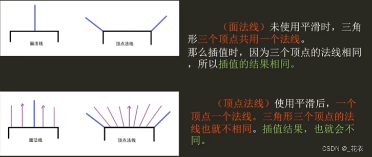
5. Vertex normal, surface normal
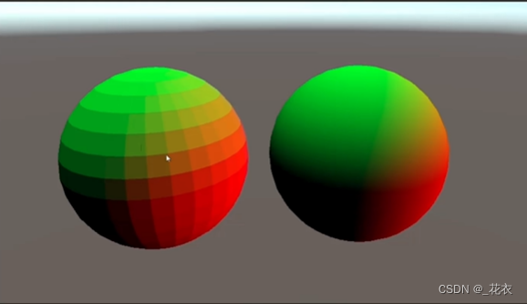
● Surface normals are essentially vertex normals, but the storage method is different
● Principle:
○ Surface normals: three vertices share a normal, and the interpolation results are the same
○ Vertex normals: Each vertex has a discovery, and the interpolation results are the same That's different
Extension: Stroke in NPR
● In NPR rendering, the vertex normal direction is usually offset in the vertex shader, and then a color is directly output in the fragment shader to achieve the stroke effect.
● When BackFacing strokes, the stroke lines are broken because there are no smooth normals between vertices.
2. What effect does the model smoothing group have on the normals?
First, let’s understand what a smooth group is.
● There is no real smooth surface. All surfaces are triangles.
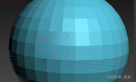
● The meaning of a smooth group: The following figure shows the brightness of the surface. It is purely an analogy. It is not an exact number. The transition between two surfaces is the brightness of the two surfaces. The smoothing group processes the lighting information between surfaces and improves their brightness and saturation.
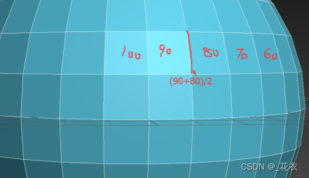
○ If one smooth group of two surfaces is 1 and the other is 2, no calculation will be performed.
○ If their smooth groups are both 1, lighting calculation will be performed, resulting in a smooth effect, which will affect the final rendering.
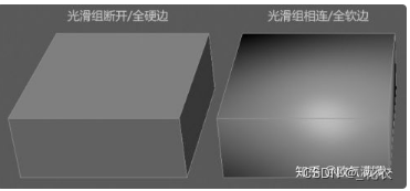
● Automatic smoothing: All faces with angles less than 45 degrees are smoothed.
● Smoothing group: A smoothing effect is achieved by processing the lighting information between faces. It is used to set the smooth display of edge lines.
● Mesh smoothing and turbo smoothing: expressing curvature by adding surfaces and dividing the surfaces more finely
● What we usually call reasonable wiring, topology is actually maintaining the consistency of two triangles (two triangles forming a four-sided surface) noodle)
②The influence of smoothing group on normals
Normal
● The meaning of baking normals is to use a picture (RGB) to store the normal direction of the high-poly model onto the surface of the low-poly model. Applying a normal map to a low-poly model will visually produce a bumpy and detailed rendering effect, making it look like a high-poly model. Normal Mapping The normal map is essentially a kind of picture, but this picture has a special purpose.
● Without the smoothing group, the baked normal map will be angular. Under normal circumstances, at least one smooth group should be given.
● Refer to the example in the link: the gradient normal map will have black edges in substancepainter (the problem of the smooth group)
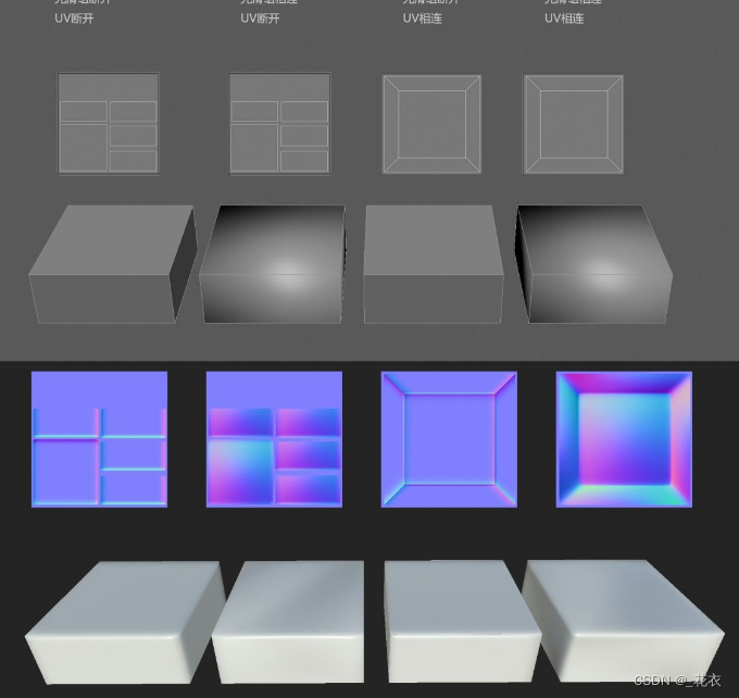
The effect of smoothing groups (soft and hard edges) and UV on normals
●
● For models connected by smooth groups, the normal maps have large gradients, which causes the normal effect of the model to be very strange (dark and bright light and shadow on the plane). When you find that your model has this kind of gradient, there must be a smoothing group problem.
● The two middle models have seams of varying degrees (the seams on the third model are very obvious, and on the second model they are weaker). If the smooth group and UV are connected or disconnected uniformly, there will be no obvious seams. When encountering seam problems, priority should be given to whether the smooth group and UV of the model are unified.