Hello everyone, I am senior Xiaohua, a blogger in the computer field. After years of study and practice, I have accumulated rich computer knowledge and experience. Here I would like to share my learning experience and skills with you to help you become a better programmer.
As a computer blogger, I have been focusing on programming, algorithms, software development and other fields, and have accumulated a lot of experience in these areas. I believe that sharing is a win-win situation. Through sharing, I can help others improve their technical level and at the same time get the opportunity to learn and communicate.
In my articles, you will see my analysis and analysis of various programming languages, development tools, and common problems. I will provide you with practical solutions and optimization techniques based on my actual project experience. I believe that these experiences will not only help you solve the problems you are currently encountering, but also improve your programming thinking and problem-solving abilities.
In addition to sharing technical aspects, I will also touch on some topics about career development and learning methods. As a former student, I know how to better improve myself and face challenges in the computer field. I will share some learning methods, interview skills and workplace experiences, hoping to have a positive impact on your career development.
My articles will be published in the CSDN community, which is a very active and professional computer technology community. Here you can communicate, learn and share with other people who love technology. By following my blog, you can get my latest articles as soon as possible and interact with me and other readers.
If you are interested in the computer field and hope to better improve your programming skills and technical level, then please follow my CSDN blog. I believe that what I share will help and inspire you, allowing you to achieve greater success in the computer field!
Let us become better programmers together and explore the wonderful world of computing together! Thank you for your attention and support!
All computer project source codes shared include documents and can be used for graduation projects or course designs. Welcome to leave a message to share questions and exchange experiences!
Summary
With the development of computer network technology, network addresses are becoming increasingly scarce and have been regarded as a valuable network resource. Just in 2019, the global IPV4 addresses have been allocated, which shows that the development of Internet information technology is so fast.
In order to solve this problem, network address translation (NAT) technology is widely used, which maps network addresses from one address domain to another. The growing shortage of IPv4 addresses is a major reason why NAT is often deployed. With the development of network technology and the improvement of security requirements, NAT has gradually evolved into a basic means to isolate internal and external networks and ensure network security. With this technology, no additional investment is required, and security purposes can be easily achieved by simply using existing network equipment. . Therefore, it is generally used for communication between enterprises, schools, Internet cafes, communities, etc. and the Internet.
The static NAT implemented in this project realizes network port mapping technology. In the deployment environment of the enterprise network, it can enable the internal servers of the enterprise to be published to the Internet for public network users to access, just like when we access Baidu, Tencent, etc. at home or through mobile phone traffic. Similar to the website, the internal system is mounted to the public network.
Keywords: NAT port mapping network enterprise network address
Abstract
With the development of computer network technology, network address is increasingly scarce, which has been regarded as a valuable network resource. Just in 2019, the global IPv4 address has been allocated, which shows that the development of Internet information technology is so fast.
In order to solve this problem, network address translation (NAT) technology is widely used. It maps network address from one address domain to another. The increasing shortage of IPv4 addresses is one of the main reasons for the frequent deployment of NAT. With the development of network technology and the improvement of security requirements, NAT has gradually evolved into a basic means of isolating internal and external networks and ensuring network security. Moreover, with this technology, it is easy to achieve the purpose of security without additional investment and simply using the existing network equipment. Therefore, it is generally used for the communication between enterprises, schools, Internet cafes, communities and the Internet.
In the deployment environment of enterprise network, the static NAT network port mapping technology researched in this paper can make the internal server of enterprise publish to the Internet for public network users to visit, which is similar to our home or mobile traffic visiting Baidu, Tencent and other websites, and mount the internal system to the public network.
Keywords: NAT Port mapping network Enterprise network address
Table of contents
1.2 Research significance... 2
Chapter 2 System Analysis... 2
2.2 Requirements analysis... 3
Chapter 3 Overview of related technologies... 5
4.1 Network design planning... 10
4.2 Network topology diagram... 11
4.5 Comprehensive wiring principles... 16
Chapter 5 Detailed Design... 17
5.2 Aggregation layer design... 17
5.3 Key technologies and difficulties... 18
5.4 Problems and solutions... 18
Chapter 6 System Testing... 18
Chapter 1 Introduction
Because the emergence of computers brought us the INTERNET, which is what people now call the Internet. Nowadays, the advent of the Internet has brought about earth-shaking changes for people, so much so that they cannot go anywhere without the Internet. The emergence of computer networks has also changed the way people use computers, allowing people to do various things without leaving home. You can connect with friends all over the world, and you can work from home... So now the Internet has penetrated into all walks of life, and is closely related to our life, work, and study. Due to the rapid development of various network technologies, companies in all walks of life have chosen to use network technology to improve the overall work efficiency and middle and senior management levels of the entire enterprise. The main purpose of enterprise network construction is platform functionalization, with the main direction of improving communication among employees within the enterprise and rapid management of middle and high-level employees.
This graduation project is based on the research and analysis of previous cases of small and medium-sized enterprises, combined with the own requirements of small and medium-sized enterprises, and then determines the realization of real information network management by enterprises. To establish networked enterprise management, the first step we need to take is to establish the enterprise's internal LAN. By establishing the enterprise LAN, we can develop various applicable special-purpose and application software. Based on the deployment of this management platform and various application software, enterprise resource sharing, information exchange, and efficient management can be achieved. The research ideas of enterprise LAN are constantly updated during the entire platform research and development process, and various requirements for establishing the LAN are completed one by one. This management network is mainly centered on routing and switching, and most of them use Cisco network products. The performance and application support of related equipment can be viewed through Cisco product manuals.
1.1 Research background
With the popularity of the Internet, one obvious fact is: the number of people and devices connected to the network is increasing every moment. Theoretically, there are only about 232 available addresses for IPv4, and in fact, only about 250 million addresses can be used by devices. Numerous reports show that there are approximately 6.5 billion people on earth, and more than 10% of them are connected to the Internet. These statistics draw our attention to a worrying reality: According to the capacity of IPv4, everyone on the earth cannot even own a computer, and IPv4 is facing a crisis of address exhaustion. In response to this problem, people have done a lot of work and efforts in the allocation and reservation of IP addresses to alleviate the worsening address shortage problem. As a standard Internet technology, NAT enables internal LAN communications to use one set of IP addresses, while external communications use another set of IP addresses, which is of great significance in the current IPv4 protocol environment. By separating Internet and LAN addresses through NAT, many addresses can be saved compared to a single global address allocation mechanism. For many enterprises that cannot apply for many globally routable public addresses, it provides a solution that allows terminals in the LAN to connect to the Internet. However, the shortcomings of NAT are a problem that cannot be ignored. Internal addresses are not routed on the public network, and users You can access others, but it is difficult to be accessed by others. On China's IP network, many users are currently using "internal addresses". This phenomenon undoubtedly has great potential harm to the development of China's IP business. This harm In fact, it has gradually shown itself. As IP telephony gradually matures at the technical level, a series of corresponding protocols and standards are released. H.323, a component of the multimedia communication series standards, and IETF's SIP, as well as those based on these standards Products of the protocol, such as IP telephone systems, media gateways, etc., have been widely used, and some network conflicts have also emerged. For example, some network entities currently restrict the passage of such end-to-end packets. These entities refer to firewalls and network address converters. . However, with the development of IP telephony in China, this series of standards and protocols will be applied in practice. Therefore, the current research direction of NAT is based on NAT traversal technology of various standards and protocols.
1.2 Research significance
In the beginning, computers could only work on a stand-alone basis, and then each department could not share data in real time, which would lead to very low efficiency in the company. Naturally, the simple manual management model cannot meet the needs of modernization. As a result, the company cannot survive and develop well. So the enterprise network had its initial network requirements, which came from the need to share LAN resources and conduct business. At that time, the smallest local area network may be considered to use a shared hub HUB to connect the printer and the file server. However, with the rapid development of the Internet today, the above simple shared technology network will definitely not be able to meet the current needs of enterprise development. Today, with the rapid development of science and technology, we need a faster, safer, more reliable and more convenient network. Technology comes to manage the business. Therefore, how to use network technology to better meet the development of current enterprises is the key issue of this topic.
1.3 Research content
This topic is based on the background of NAT application and takes NAT traversal technology as the research object. First, the basic principles and common technology types of NAT are introduced. Next, the existing defects are found through the application of NAT in actual network environments, and the implementation principles of currently popular solutions are analyzed. Finally, one's own solution is proposed and its analysis is carried out. The theoretical feasibility has also been confirmed to be feasible in actual experiments, and the scheme is demonstrated and simply designed. In the first chapter, the background of NAT and the research purpose of this topic are briefly described; in the second chapter, the main Explain the feasibility analysis of network construction; Chapter 3 introduces the definition of NAT, the principle of NAT, NAT classification and NAT technology types, etc. The defects of NAT application and various current NAT solutions and their respective advantages and disadvantages; Fourth Chapter 5 introduces his own solution in more detail, conducts theoretical analysis and experimental verification, and finally compares it with existing solutions based on the demonstration results; Chapter 5 gives an example of solution implementation and related program flow diagrams. ;Chapter 6 is a test of the entire subject.
Chapter 2 System Analysis
2.1 Feasibility analysis
2.1.1 Technical feasibility
Basic principles of NAT technology. NAT technology can help solve the headache problem of IP address shortage, and can isolate internal and external networks and provide a certain network security guarantee. The way it solves the problem is to use the internal local address in the internal network, and translate the internal local address into the internal global address through NAT for use on the Internet. The specific method is to use the legal IP address in the address field in the IP packet. replace. NAT functionality is usually integrated into a router or a separate NAT device.
2.1.2 Economic feasibility
Ethernet has a series of advantages such as low cost, high reliability, etc., so it has been widely used [1]. Ethernet technology can be quickly and reliably deployed within an enterprise or between floors. Combined with various wide area network technologies, it can realize interconnection networks between enterprises and even globally. Ethernet accounts for the majority of networks interconnected with the international Internet. Nowadays, with the development of the Internet and continuous updates to Ethernet, it has more stably occupied the top spot in local area network products.
Starting from the economic benefits of the enterprise, the sharing of data resource information is realized through the local area network, which improves internal and external exchanges and communication, allowing the enterprise to quickly grasp various developments in the rapidly changing network information; realize office automation, for internal management It is more convenient, makes full use of relevant resources, greatly improves work efficiency, and effectively reduces costs. Through the enterprise's internal LAN, it is separated from the Internet, effectively improving network security and avoiding unnecessary losses caused by resource theft and malicious damage.
2.1.3 Operational feasibility
According to the current development status of enterprises, the demand for information, collection, processing and other tasks of enterprises are constantly expanding. The original single-machine working method is far from meeting the current needs, and the single-machine working method is not conducive to the communication between various fields. The sharing of information and resources has greatly reduced work efficiency and affected the development of enterprises. A high-efficiency, high-performance, and high-reliability network can easily and satisfactorily solve these problems. Therefore, it is feasible to establish a complete enterprise network system and use this network system to change the existing management system to meet the enterprise's current network needs.
2.2 Demand analysis
2.2.1 Overall demand analysis
With the development of science and technology, the scale of enterprises continues to expand, and the team of managers continues to expand. The current network structure can no longer meet the needs of current development. The main manifestations include network instability, frequent network jitter, and network line connections that are expensive, long-term, difficult to manage, and unsuitable for implementation. Therefore, a network and system platform with standardized design, complete functions, excellent performance, safety and reliability, good scalability and availability, manageability and easy maintenance should be established to improve the work of the company's employees in a high-efficiency, high-speed and low-cost manner. Efficiency and execution efficiency are very necessary. Therefore, we must use high-end computers, network equipment, and software, and use advanced and mature network communication technology for networking and advanced system integration technology and management models. Establishing an efficient office network system is an urgent task for the company.
2.2.2 Non-functional requirements
1.Office user needs
Several functions of the enterprise network connect all computers and network devices in the enterprise; support about a hundred computers to access the Internet at the same time; the enterprise has multiple departments, and different departments can access each other, but there are restrictions; the enterprise must have its own corporate website, It can be accessed from the external network; the enterprise must have its own FTP system;
2. Operation and maintenance personnel needs
Equipment selection must be technologically advanced, versatile, and must be easy to manage and maintain. It should have good scalability and upgradeability in the future to protect the company's investment. The equipment must meet the functions and performance of the project and have a good price/performance ratio. When selecting equipment, it must be a mainstream product with sufficient strength and market share, and it must also have good after-sales service. All network equipment can be monitored, managed and set up with appropriate network management software; international unified standards must be adopted.
3.Department needs
The company's network department mainly includes the following:
Sales;
Personnel Department;
Finance Department;
manager's room;
Office 1;
Office 2;
Technical Department.
Each department must have access to the internal mail server, and emails can be sent and received between departments. Computers within the company are connected using the company's internal system. 1000M optical fiber access is used between the company's internal network and the Internet. The company sets up a Web server internally to provide the company's image and e-commerce services to the Internet. To ensure security, protective measures should be adopted between the Internet and the company's internal network to prevent unauthorized access to the internal network from the outside world.
4.Performance requirements
The entire company plans to use 1000M optical fiber to access the Internet provided by the operator. Performance requirements: including service efficiency, service quality, network throughput rate, network response time, data transmission speed, resource utilization, reliability, performance/price ratio, etc.;
According to the particularity of this project, voice points and data points use the same transmission medium, that is, Category 5e 4-pair twisted pair cables are uniformly used to realize the need for mutual backup of voice and data; the connecting cables between buildings are exposed outdoors. Affected by the sunshine, rainforest and lightning interference all year round, the commonly used twisted pairs, thin coaxial cables, thick coaxial cables and optical cables etc.
From the perspective of wired transmission media, optical cable is the most suitable transmission medium from the aspects of anti-interference, anti-corrosion, high bandwidth and allowed transmission distance.
Chapter 3 Overview of Related Technologies
3.1 VLAN technology
VLAN (Virtual Local Area Network) is a technology that implements virtual workgroups by dividing the devices in the LAN into network segments logically rather than physically. IEEE promulgated the IEEE 802.1Q protocol standard draft in 1999 to standardize VLAN implementation. Virtual LAN (VLAN) refers to a network technology that allows sites in the network to be flexibly added to different logical subnets as needed, regardless of their physical location. Virtual LAN based on switched Ethernet In switched Ethernet, VLAN technology can be used to divide the physical network connected by switches into multiple logical subnets. That is, broadcast packets sent by a station in a VLAN will only be forwarded to stations belonging to the same VLAN. In switched Ethernet, each site can belong to different virtual LANs. The sites that constitute a virtual LAN are not restricted to their physical locations. They can be connected to the same switch or to different switches. Virtual LAN technology makes the network topology very flexible. For example, users on different floors or in different departments can join different virtual LANs as needed.
3.2 OSPF technology
3.2.1 How OSPF works
OSPF is the abbreviation of Open Shortest Path First. It is a link state-based interior gateway protocol developed by the IETF organization. Currently, OSPF Version2 (RFC2328) is used for the IPv4 protocol.
OSPF has the following characteristics:
(1) It has a wide range of adaptability, supports networks of various sizes, and can support up to several hundred routers.
(2) Fast convergence, which can send update messages immediately after the network topology changes, so that this change can be synchronized in the autonomous system.
(3) No self-loop Since OSPF uses the shortest path tree algorithm to calculate routes based on the collected link status, the algorithm itself guarantees that no self-loop routes will be generated.
(4) Area division allows the network of autonomous systems to be divided into areas for management, and the routing information transmitted between areas is further abstracted, thereby reducing the occupied network bandwidth.
(5) Equal-cost routing supports multiple equal-cost routes to the same destination address.
When network devices with routing functions run the OSPF protocol, the devices will begin to exchange hello messages. The hello messages usually contain some basic routing information, and then DBD messages will be exchanged. The article briefly describes its own LSA information, and compares it with its own LSA information through the received DBD message. If part of the LSA information is missing, an LSR message is sent to request that the missing part be sent. At this time, the peer device will send a LSU message, LSU mainly updates LSA information, and then sends ack message to ensure security. Finally, LSU is stored in the LSA database to form LSDB, and then runs the SPF algorithm to calculate the optimal path and form a routing table.
Table 3-1 Comparison table between RIP and OSPF
| RIP |
OSPF |
| Based on the distance vector algorithm, hop count is used as the measurement method and the impact of bandwidth is ignored. |
Based on the link status, the link cost is used as the measurement method, and the bandwidth is used as the reference value. The measurement method is more scientific. |
| The hop count of RIP is limited to 15, which limits the network scale of RIP. |
There is no limit on the number of hops, and it is applicable to larger networks. |
| Route updates and selections are performed according to route advertisements. Routers do not understand the entire network topology and are prone to routing loops. |
Each router can grasp the topology of the entire network and calculate routes through the shortest path priority algorithm SPF (Shortest Path First), without causing routing loops. |
| The convergence speed is slow, and routing updates will go through a period of suppression and garbage collection, which can easily lead to routing inconsistencies between routers. |
Convergence is fast because routing updates are timely and quickly delivered to the entire network. |
| Cannot handle variable length subnet masks (VLSM). |
Able to handle VLSM and flexibly allocate IP addresses. |
3.3 DHCP technology
DHCP , Dynamic Host Configuration Protocol, formerly the BOOTP protocol, is a LAN network protocol that uses the UDP protocol to work. There are two commonly used ports: 67 (DHCP server), 68 (DHCP client) . DHCP is usually used in LAN environments. Its main function is to centrally manage and allocate IP addresses, allowing the client to dynamically obtain information such as IP addresses, Gateway addresses, DNS server addresses, and improve address usage. Simply put, DHCP is a protocol that automatically assigns IP addresses and other information to intranet machines without requiring an account or password to log in .
There are several types of DHCP messages:
- DHCP DISCOVER : The packet sent by the client to start the DHCP process is the beginning of the DHCP protocol.
- DHCP OFFER : The response made by the server after receiving DHCP DISCOVER . It includes the IP given to the client ( yiaddr ), the client's MAC address, the lease expiration time, the server's identifier and other information
- DHCP REQUEST : The client responds to the DHCP OFFER issued by the server. It will also be used when renewing the lease.
- DHCP ACK : A successful confirmation message sent by the server after receiving the DHCP REQUEST from the client. When establishing a connection, the client will confirm that the IP and other information assigned to it can be allowed to be used after receiving this message .
- DHCP NAK : The opposite message of DHCP ACK , indicating that the server rejected the client's request.
- DHCP RELEASE : Generally occurs when the client is shut down or offline. This message will cause the DHCP server to release the IP address of the client that sent this message.
- DHCP INFORM : A message sent by the client to request some information from the server
- DHCP DECLINE: When the client finds that the IP address assigned by the server cannot be used (such as an IP address conflict), it will send this message to notify the server that the use of the IP address is prohibited.
DHCP workflow :
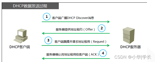
Figure 3-1 DHCP workflow
3.4 STP technology
STP (Spanning Tree Protocol) is the English abbreviation of Spanning Tree Protocol. It can be used to establish tree topology structures in computer networks. Its main function is to prevent redundant links in the bridge network from forming loops. But certain factors can cause STP to fail, and troubleshooting can be difficult, depending on the network design. The Spanning Tree Protocol is suitable for network equipment from all manufacturers. There are differences in configuration and functional intensity, but the principles and application effects are the same. The basic principle of STP is to determine the network topology by transmitting a special protocol message, Bridge Protocol Data Unit (BPDU), between switches. There are two types of BPDU, configuration BPDU (Configuration BPDU) and TCN BPDU. The former is used to calculate a loop-free spanning tree, and the latter is used to shorten the refresh time of MAC table entries when the layer 2 network topology changes (shortened from the default 300s to 15s).
Spanning Tree Protocol (STP) is defined in the IEEE 802.1D document. The principle of this protocol is to construct the network topology according to the tree structure, eliminate loops in the network, and avoid broadcast storm problems caused by the existence of loops.
The basic idea of Spanning Tree Protocol (STP) is to construct the network topology according to the "tree" structure. The root of the tree is a bridge device called the root bridge. The root bridge is established by the BID (Bridge ID) of the switch or bridge. ) is determined, the device with the smallest BID becomes the root bridge in the Layer 2 network. The BID is composed of the bridge priority and the MAC address. The number of bytes of the bridge priority of devices from different manufacturers may be different. Starting from the root bridge, a tree is formed step by step. The root bridge regularly sends configuration BPDUs. Non-root bridges receive configuration BPDUs, refresh the best BPDUs, and forward them. The best BPDU here refers to the BPDU sent by the current root bridge. If a lower-level BPDU is received (the newly connected device will send a BPDU, but the BID of the device is larger than the current root bridge), the device that receives the lower-level BPDU will send its best stored BPDU to the newly connected device. To inform it of the root bridge in the current network; if the received BPDU is better, the spanning tree topology will be recalculated. When the non-root bridge has not received the best BPDU after the maximum age (Max Age, default 20s) since the last time it received the best BPDU, the port will enter the listening state, and the device will generate TCN BPDU and send it from The root port forwards out, and the upper-level device that receives the TCN BPDU from the designated port will send a confirmation, and then send the TCN BPDU to the upper-level device. This process continues until the root bridge, and then the root bridge will carry the tag in the configuration BPDU sent thereafter. It indicates that the topology has changed. After receiving the change, all devices in the network shorten the refresh time of MAC table entries from 300s to 15s. The entire convergence time is about 50s.
Spanning Tree Protocol is a data link layer protocol agreed in IEEE 802.1D. It is used to solve the network loop problem caused by building redundant links at the core layer of the network by transmitting bridge protocol data units ( Bridge Protocol Data Unit (BPDU for short), by using the STA spanning tree algorithm to elect the root bridge, root port and designated port, the network will eventually form a tree-structured network, in which the root port and designated port are both in the forwarding state. Other ports are disabled. If the network topology changes, the spanning tree topology will be recalculated. The existence of spanning tree protocol not only solves the network robustness requirement of redundant links in the core layer network, but also solves the problem of "broadcast storm" caused by physical loops formed by redundant links.
However, due to the limitations of the protocol mechanism itself, STP protection speed is slow (even the convergence speed of 1s cannot meet carrier-class requirements). If STP technology is used within the metropolitan area network, turbulence in the user network will cause turmoil in the operator's network. . In the MSTP ring network, since the SDH protection switching time is much faster than the STP protocol convergence time, the system still uses SDH MS-SPRING or SNCP, and the general switching time is within 50ms. However, during the test, the switching time of some Ethernet services was 0 or less than a few milliseconds because of the large internal cache. SDH protection switching actions are invisible to the MAC layer. These two levels of protection can work in coordination and set a certain "hold-off" time. Generally, multiple switching problems will not occur.
The port status of the spanning tree is divided into the following parts:
Blocking: At this time, the Layer 2 port is a non-designated port and will not participate in the forwarding of data frames. The port determines the location and root ID of the root switch by receiving BPDUs, and what state each switch port should be in after the STP topology convergence is completed. By default, the port will stay in this state for 20 seconds.
Listening (listening state): At this time, the spanning tree has determined that this port should participate in the forwarding of data frames based on the BPDU received by the switch. As a result, the switch port will no longer be satisfied with receiving BPDUs, but will also start sending its own BPDUs, thereby notifying the adjacent switches that the port will participate in forwarding data frames in the active topology. By default, the port will stay in this state for 15 seconds.
Learning (learning state): This layer 2 port is ready to participate in the forwarding of data frames and begins to fill in the MAC table. By default, the port will stay in this state for 15 seconds.
Forwarding: This Layer 2 port has become an integral part of the active topology. It will forward data frames and send and receive BPDUs at the same time.
Disabled: This Layer 2 port will not participate in spanning tree and will not forward data frames.
3.5 NAT technology
3.5.1 Principles of NAT technology
NAT is installed on a device with NAT function between the internal network and the external network. The internal host needs to communicate with the external network.
When communicating with each other, NAT is responsible for address translation, so a translation table (NAT
table) to store the corresponding address translation information. If a domain has multiple exits, then it must also be ensured that each NAT has
Have the same translation table. Simply put, NAT uses internal addresses in the internal LAN network, and when the internal
When a point wants to communicate with an external network, it replaces the internal address with a public address at the gateway, thereby
It can be used normally on the internet. With the help of NAT, the private (reserved) address of the "internal" network is converted into a legal IP address when packets are sent through the router.
3.4.2 NAT related terms
(1) Internal network (Inside): refers to the internal local area network, which is the same as the network defined as inside on the border router.
interface is connected.
(2) External network (Outside): refers to all networks except the internal network, usually the Internet, and its boundaries.
Connect to the network interface defined as outside on the router.
(3) Inside Local Addreds: refers to the IP address used by hosts in the internal LAN.
These addresses are usually private network addresses.
(4) Inside Global Addreds: refers to the public address used by some hosts in the internal LAN.
network IP address. For example, if the server is placed in the local area network, the legal public IP address used by the server.
(5) Outside Local Address: The IP address used by the host in the external network. This
These IP addresses are not necessarily public network addresses.
(6) Outside Global Addreds: IP addresses used by hosts in the external network,
These IP addresses are globally routable, legal public IP addresses.
(7) Address Pool: refers to multiple legal public IP addresses that can be used for NAT translation.
3.4.4 Types of NAT technology
(1) Static address translation
It refers to converting the private IP address of the internal network into a public IP address. The IP address pair is one-to-one.
, is immutable, a certain private IP address is only converted to a certain public IP address. With the help of static conversion,
It enables external networks to access certain specific devices (such as servers) in the internal network.
(2) Dynamic address translation
Dynamic NAT pool (Pooled NAT) uses dynamic allocation method to map the IP addresses of the internal network and the external network. Using NAT pooling means that many internal users can be defined in the intranet and share a few external IP addresses through dynamic allocation. In a dynamic NAT environment, the number of users that can communicate with the outside world at the same time is limited by the number of addresses in the address pool. When the remote user connects, the dynamic address NAT will assign him an IP address in the address pool that is not assigned to other users. When the user disconnects, this IP address will be released and reserved for future use. This shows that the dynamic address NAT must also maintain a dynamic table to record the correspondence between private IP addresses and global IP addresses, because the correspondence between them is not as one-to-one as static NAT, so dynamic NAT is much more complicated than static NAT. It should be noted that after all the dynamically allocated external IP addresses in the NAT pool are occupied, subsequent NAT translation applications will fail and a host unreachable ICMP packet will be returned. Only when a user ends the connection, the allocation to it will be automatically released. After the global address is obtained, new address translation requirements can be executed.
(3) Port multiplexing
Port address translation (PAT) refers to changing the source port of outgoing data packets and performing port translation, that is, port address translation (PAT, Port Address Translation). Port multiplexing is used. All hosts in the internal network can share one legal external IP address to access the Internet, thus maximizing savings on IP address resources. At the same time, it can hide all hosts within the network to effectively avoid attacks from the Internet. Therefore, port multiplexing is currently the most widely used method in the network.
3.4.5 Existing problems with NAT technology
In IPv4 networks, the shortage of public IP addresses has led to the widespread use of private IP addresses in user networks. In order to realize that IP packets sent from the user's private network can be routed on the public network, special translation equipment is needed at the interface between the user network and the public network - a network address translator (NAT) to realize the public address and private address in the IP header. translation. As a standard Internet technology, NAT enables internal LAN communications to use one set of IP addresses and external communications to use another set of IP addresses, which is of great significance in the current IPv4 protocol environment. By separating Internet (public domain) and LAN (private domain) addresses through NAT, many addresses can be saved compared to a single global address allocation mechanism. On the one hand, this provides many enterprises that cannot apply for many globally routable public addresses with a solution that allows all terminals in the LAN to connect to the Internet. On the other hand, because terminals within the private network cannot communicate directly with the outside world, the external network cannot see There are no hosts on the internal network, thus providing certain security features of the internal network and acting as a firewall in this regard. But so is NAT's flaw - an issue that cannot be ignored.
The internal address has no route on the public network. Users can access it from others, but it is difficult to be accessed by others. On my country's IP network, many users are currently using "internal addresses." This phenomenon undoubtedly has great potential harm to the development of my country's IP business. This harm has actually been gradually revealed. As IP phones gradually mature at the technical level, a series of protocols and standards have been released, such as ITU-T's H. 323 and IETF's SIP, as well as products based on these standard protocols, such as IP phone systems. , media gateways, etc. have been widely used, and some network conflicts have also been highlighted. For example, some network entities currently restrict the passage of such end-to-end packets. These entities refer to firewalls and network address converters. Voice and video applications based on protocols such as H.323, SIP, MGCP and H.248 need to implement destination addressing through IP addresses and port parameters in signaling messages. Therefore, NAT traversal requires not only the TCP/UCP layer The port information and the source address and destination address of the IP layer need to be transformed, and the relevant address information in the IP packet payload needs to be transformed; however, NAT only modifies the source address, source port, destination address, and destination of the data packet when the data packet passes through. Port, any information in the IP packet payload, including address information, is not modified, which makes communication unable to proceed normally, and this problem needs to be solved urgently.
3.4.5 NAT technical working process
On the terminal:
When an application wants to communicate with a server, it opens a socket associated with the source IP address, source port, destination IP address, destination port, and network protocol. This identifies the two endpoints required for communication. When an application utilizes this socket to transfer information, the client's private IP address (source IP address) and port (source port) are inserted into the source field of the packet. The destination field of the packet will contain the server's IP address (remote host - destination IP address) and port. Since the packet is destined for a location outside the private network, the client will grab the packet and send it to the default gateway. The default gateway in this case is the NAT device.
On the NAT device:
The NAT device will intercept the outgoing packet. Then create a port mapping using the target IP address (server), target port, the NAT device's external IP address, external port, network protocol, or the client's internal IP address and port. The NAT device will maintain a table composed of these mappings and store the mapping of the port in the table. The external IP address and port is the public IP address and port used for this data traffic in place of the internal client IP address and port. The NAT device then translates the packets coming from the client's internal IP address and port by converting the source field of the packets to the NAT device's public IP address and port. The packet is then sent through the external network and eventually reaches the destination server.
Chapter 4 System Design
4.1 Network design planning
4.1.1 Design principles of network architecture
1. Security and reliability: It can ensure the security and reliability of the entire network architecture. When building the network architecture, redundant backup processing is designed for the relevant core, aggregation layer and access layer network equipment, and relevant security policies can be set in a timely manner. To prevent internal data leaks and hacker attacks
2. Comply with relevant national regulations: When building this enterprise network, we strictly abide by the latest national order No. 82 and other relevant documents, relevant multimedia protocols, and higher requirements for communication technology, as well as some common international standard technologies and National Security Registration Protection
3. Economical, practical and scalable: When it can meet the various needs of the enterprise, choose the most cost-effective network equipment and servers that are also convenient for subsequent upgrades.
4. Advanced practicality: When designing and building an enterprise network, you should consider using advanced and reliable computing to ensure that the enterprise network does not fall behind the trend of modern network development and can follow the development of the times.
4.1.2 Network hierarchical structure design
The small and medium-sized enterprise network designed this time adopts a three-layer hierarchical structure design. The design of the three-layer network architecture is to divide the complex network design into several levels, and each level focuses on certain specific functions, so that it can One big complex problem turns into many small, simple problems. The network designed by the three-layer network architecture has three layers: the core layer (the high-speed switching backbone of the network), the aggregation layer (providing policy-based connections), and the access layer (connecting workstations to the network).
4.2 Network topology diagram

Figure 4.1 Network topology diagram
4.3 IP address planning
The principles of network IP address planning are:
(1) Simplicity: IP address allocation should be simple and clear, avoiding the use of more complex masks on major networks.
(2) Continuity: Assign a series of consecutive addresses to a network area to increase the processing speed of the router.
(3) Scalability: The addresses allocated to a network area should have a certain capacity so that the continuity of the addresses can be guaranteed when the number of terminals further increases in the future.
(4) Manageability: Address planning should be divided into primary and secondary addresses. Changes in addresses in a certain area cannot affect the overall situation.
(5) Security: Network addresses should be planned to different network segments according to work content for management.
Table 4.1 IP address planning table
| department |
network segment |
mask |
gateway |
| Sales |
10.10.0.0 |
255.255.255.0 |
10.10.0.254 |
| Finance Department |
10.10.1.0 |
255.255.255.0 |
10.10.1.254 |
| Personnel Department |
10.10.2.0 |
255.255.255.0 |
10.10.2.254 |
| Office 1 |
10.10.3.0 |
255.255.255.0 |
10.10.3.254 |
| office 2 |
10.10.4.0 |
255.255.255.0 |
10.10.4.254 |
| Technology Department |
10.10.5.0 |
255.255.255.0 |
10.10.5.254 |
| Manager's room |
10.10.6.0 |
255.255.255.0 |
10.10.6.254 |
| DNS server |
10.10.200.53 |
255.255.255.0 |
10.10.200.254 |
| WEB server |
10.10.200.80 |
255.255.255.0 |
10.10.200.254 |
| Mail Server |
10.10.200.25 |
255.255.255.0 |
10.10.200.254 |
4.4 Equipment selection
When selecting equipment, it is recommended to choose Cisco equipment. Cisco has always been a leading company in the field of network equipment, and the equipment is stable and cost-effective.
4.4.1 Core layer equipment selection:
The Cisco Catalyst 3750 series products are professional-level enterprise switches. They have successfully won the market with their outstanding innovative features and leading technology in the industry, and have performed well in terms of sales and reviews. In addition, we can also learn that the Cisco Catalyst 3750 series switches have outstanding practicality and cost-effectiveness in the industry, and can meet the different needs of a variety of scenarios. Then the next announcement will give you a detailed introduction to the parameters of the Cisco Catalyst 3750 series:
Table 4.1 3750 parameters
| product type |
Enterprise grade switch |
| MAC address table |
12K |
| Port structure |
non-modular |
| Number of ports |
26 |
| Port description |
24 Ethernet 10/100Mpps ports, 2 SFP-based Gigabit Ethernet ports |
| application level |
third floor |
| Transmission rate |
10/100/1000Mbps |
| exchange method |
store-and-forward |
| Backplane bandwidth |
32Gbps |
| Stacking function |
Stackable |
| Packet forwarding rate |
6.5Mpps |
| Transmission mode |
Support full duplex |
| VLAN |
support |
| Product Size |
445×301×44mm |
| QOS |
support |
| network management |
SNMP, CLI, Web, management software |
The product outline of Cisco Catalyst 3750 is as follows:
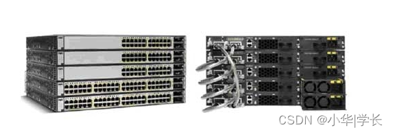
Figure 4.2 Cisco Catalyst 3750 Series Switches
4.4.2 Aggregation layer switch
Choose Cisco Catalyst 2960 series switches at the aggregation layer. Because of its network characteristics similar to high-end switches and its high-density fixed ports, the 2960 series switches are generally suitable for access switches in campus networks. The 2960 series switches can support a lot of advanced switching features, such as network admission control (NAC), advanced quality of service (QoS), integrated security, flexibility, etc., and are reasonably priced and cost-effective. Can provide intelligent services to the edge of the network.
In terms of performance, the 2960 series switches support 32Gbit/s switching arrays; support EtherChannel links; provide up to 48 10/100BASE-FX ports and 2 10/100/1000BASE-T Ethernet ports; support up to 8Gbit /s aggregate bandwidth; supports up to 8,000 MAC addresses. Spanning tree redundancy and 802.3ad are also supported.
In terms of security, the 2960 series switches support 802.1x advanced security features; support private VLAN, port security, DHCP Snooping and interface tracking; support TACACS+ and RADIUS authentication, etc., enable remote access and remote management, and support encryption in remote sessions Administrator's traffic, effectively protecting network security.
Table 4.2 2960 parameters
| Product number |
2960 |
| application level |
Second floor |
| product type |
Managed switch |
| Transmission rate |
10/100/1000Mbps |
| processor |
APM86392 600MHz dual core |
| Product memory |
Flash memory: 128MB |
| DRAM memory |
512MB |
| Backplane bandwidth |
108Gbps |
| exchange method |
store-and-forward |
| Packet forwarding rate |
71.4Mpps |
| Port structure |
non-modular |
| Number of ports |
48 |
| Port description |
24 10/100/1000 interfaces, 4 SFP interfaces |
| Transmission mode |
Full duplex/half duplex adaptive |
| voltage |
AC 100-240V,50-60Hz |
| Product Size |
45×279×445mm |
| 产品重量 |
4kg |
| 平均无故障时间 |
564,910小时 |
Cisco Catalyst 2960的产品外形图如下:

图 4-2 Cisco Catalyst 2960系列交换机
4.4.3 路由器选型
局域网出口路由器选择思科2911路由器,具体参数如下:
表4.3 2911参数
| 路由器类型 |
多业务路由器 |
| 网络协议 |
IPv4,IPv6,静态路由,IGMPv3,PIM SM,DVMRP,IPSec |
| 传输速率 |
10/100/1000Mbps |
| 端口结构 |
模块化 |
| 扩展模块 |
1个服务模块插槽数+4个EHWIC插槽+2个双宽度EHWIC插槽(使用双宽度EHWIC插槽将占用两个EHWIC插槽)+1个ISM插槽+2个板载DSP(PVDM)插槽 |
| 防火墙 |
内置防火墙 |
| Qos支持 |
支持 |
| VPN支持 |
支持 |
| 产品内存 |
DRAM内存:512MB,最大2GB |
| FLASH内存:256MB |
FLASH内存:256MB |
| 电源电压 |
AC 100-240V,47-63Hz |
| 产品认证 |
UL 60950-1,CAN/CSA C22.2 No. 60950-1,EN 60950-1,AS/NZS 60950-1,IEC 60950-1 |
| 产品尺寸 |
44.5×438.2×304.9mm |
| 产品重量 |
9.5kg(完整配置) |
| 环境标准 |
工作温度:0-40℃ |
| 工作湿度:10%-85%RH |
工作湿度:10%-85%RH |
| 存储温度:-40-70℃ |
存储温度:-40-70℃ |
| 存储湿度:5%-95%RH |
存储湿度:5%-95%RH |
| 其它性能 |
基于硬件的嵌入式密码加速(IPSec+SSL) |
下图为2911的产品外形图:

图4.3 2911路由器
4.5 综合布线原则
综合布线系统是建筑物或建筑群内的信息传输系统。它使话音和数据通信设备、交换机设备、信息管理系统及设备控制系统、安全系统彼此相连,也使这些设备与外部通信网络连接。它包括建筑物到外部网络或电话局线路上的连线、与工作区的话音或数据终端之间的所有电缆及相关联的布线部件。布线系统由不同系列的部件组成,其中包括:传输介质、线路管理硬件、连接器、插座、插头、适配器、传输电子线路、电器保护设备和支持硬件。
建筑物结构化综合布线网是由六个独立的子系统组成:
工作区(WORK AREA)子系统---由工作区内的终端设备连接到信息插座的连接电缆组成。常用设备是计算机(PC,工作站,中端,打印机),电话,传真机等设备。
管理子系统(ADMINISTRATION)--由交叉连接、直接连接配线的(配线架)连接硬件等设备所组成。实现配线管理,其设计很完善,使用颜色编码,很容易追踪和跳线,体积小比传统配线箱节省50%空间。
水平子系统(HRIZONTAL--由每一个工作区的信息插座开始,经水平布置一直到管理区的内侧配线架的线缆所组成。实现信息插座和管理子系统间(跳线架)的连接,常用六类双绞线实现这种连接。
主干线(RISER; BACKBONE)子系统---由建筑物内所有的(垂直)干线多对数线缆组成,即多对数铜缆和多模多芯光纤以及将此线缆连接到其他地方的相关支撑硬件所组成。实现计算机设备、程控机PBX和各管理子系统间的连接。常用通信介质是光纤,使系统传输率达到1000MBPS以上。
设备间子系统(EQUIPMENT)---由设备间的线缆、连接器和相关支撑硬件组成。实现布线系统与设备的连接,主要为配合不同设备有关的适配器。
建筑群子系统---将一个建筑物中的线缆延伸到建筑物群,实现楼宇之间布线,连接到另一些建筑物中的通讯设备和装置上,它由电缆、光缆和入楼处线缆上过流过压的电器保护设备等相关硬件组成。
综合布线系统本身具有很高的兼容性,根据用户要求,本方案为开放式结构,能支持话音及多种计算机数据和图像传输系统。系统能兼容话音、数据、图像的传输,并可与外部公用网络进行连接。
第5章 详细设计
在通信网络当中,应当对网络的生存能力和业务能力进行共同的考虑,才能更好的确保网络功能的正常发挥。在设计网络可靠性的时候,应当满足网络可行性,也就足限定费用条件的限制下,最大程度上提高网络的可行性。或者是在满足网络可行性的条件下,尽可能降低费用。
在网络设计方面,已经拥有很多的研究成果,但是,这些相关的研究只对网络的业务能力进行关注,却缺乏网络可靠性方面的思考。如果有一些网络部件失效,将会极大的影响网络的业务性能。因此在进行网络设计时,既要考虑到网络的业务能力,也要充分的认识到网络的可靠性
在COST239欧洲光纤网的设计过程中,采用了进化规划和遗传算法,有效的降低了网络造价,同时具有网络冗余。其网络拓扑结构为网状,适用于具有对等关系、节点数较少的广域网拓扑的设计。此外,网络拓扑的可靠性设计也十分重要。对此环形网络可靠性较高,但设计难度较高.尤其是双向自愈环形网络更为复杂。因此,可采用遗传算法来设计环形网,同时兼顾路由的选择和带宽的分配。
在子网划分的过程中,可以建立新的网络适应度函数,这样能够极大的提高子网划分的平衡性。结仓实际情况,可对网络划分的方式进行优化和改送, 使其能够自动进行网络的划分。由于遗传法具有一.定的局限性,容易引起局部最优的问题,可以在遗传算法中利用慎拟退火法米改进其中的选择算子。同时在变异操作中,进行白适应控制技术的应用.能够有效提高收敛速度.改进子网划分的逼近精度。
在路由选择方面,进化算法已经进行了很多的相关研究。例如,对于计算机通信的容量分配和路由选择,也就是分别选择一条路由给每一对通信节点,同时提供一个容星值给网络中的每一 条链路。这样,就能够有效的降低网络规划设计的整体费用。此外,在电信网.络当中,对于带宽分配、波长分配频率分配等方面问题的解决.都很好的体现出了进化算法中较高的通用性和鲁棒性,同时方法十分简单
本项目的网络设计考虑到中小型企业的日常办公和业务办理,网络拓扑结构采用的是双线冗余的机制,网关部署核心交换机,核心负责查询路由表进行转发,互联网接入设备负责NAT的转换和内部服务器的映射工作,让互联网用户通过设备配置的静态NAT映射可直接访问内部WEB服务器来浏览企业官网,汇聚交换机主要就是上联核心交换机,下联各部门接入交换机,让核心上的流量数据清晰。网络部署原则:
先进性原则:以先进、成熟的网络通信技术进行组网,支持数据、语音和视频图像等多媒体应用,采用基于交换的技术代替传统的基于路由的技术,并且能确保网络技术和网络产品在几年内基本满足需求。、
开放性原则:企业网的建设应遵循国际标准, 采用大多数厂家支持的标准协议及标准接口, 从而为异种机、异种操作系统的互连提供便利和可能。
可管理性原则:网络建设的一项重要内容是网络管理,网络的建设必须保证网络运行的可管理性。在优秀的网络管理之下,将大大提高网络的运行速率,并可迅速简便地进行网络故障的诊断。
安全性原则:信息系统安全问题的中心任务是保证信息网络的畅通,确保授权实体经过该网络安全地获取信息,并保证该信息的完整和可靠。网络系统的每一个环节都可能造成安全与可靠性问题。
灵活性和可扩充性:选择网络拓扑结构的同时还需要考虑将来的发展,由于网络中的设备不是一成不变的,如需要添加或删除一个工作站,对一些设备进行更新换代,或变动设备的位置,因此所选取的网络拓扑结构应该能够容易的进行配置以满足新的需要。
稳定性和可靠性:可靠性对于一个网络拓扑结构是至关重要的, 在局域网中经常发生节点故障或传输介质故障,一个可靠性高的网络拓扑结构除了可以使这些故障对整个网络的影响尽可能小以外,同时还应具有良好的故障诊断和故障隔离功能。
高带宽:由于企业网络应用的特殊性 , 它对整个网络系统的性能要求相对来说比较高。 其中,网络速率要求主要的信息点100M交换到桌面, 园区网中各终端间具有快速交换功能。为了支持数据、话音、视像多媒体的传输能力,在技术上要到达当前的国际先进水平。 要采用最先进的网络技术, 以适应大量数据和多媒体信息的传输, 既要满足目前的业务需求, 又要充分考虑未来的发展。 为此应选用高带宽的先进技术。
QoS 保证:随着网络中多媒体的应用越来越多, 这类应用对服务质量的要求较高,本网络系统应能保证 QoS,以支持这类应用。
IP Multicast:由于园区网络中包含许多多媒体应用通信, 会存在许多的广播信息, 占用大量的带宽资源。所以网络系统应能支持 IP Multicast ,可以减少网络中不必要的广播,节省主干的带宽。
符合IP发展趋势的网络:在当前任何一个提供服务的网络中, 对IP的支持服务是最普遍的, 而IP技术本身又处在发展变化中,如 IpV6,IP QoS,IP Over SONET等等新兴的技术不断出现,企业网络必须跟紧 IP发展的步伐,也就是必须选择处于 IP发展领导地位的网络厂商。
5.1 核心层设计

图5.1 核心层设计
核心层的功能主要是实现骨干网络之间的优化传输,是所有流量的最终承受者和汇聚者核心层设计任务的重点通常冗余能力、可靠性和高速的传输。随着网络时代的到来,企业的网络也在不停地发展业务流量、分支接入 都在考验着核心网络的承载能力,因此对核心层网络的设计以及规划也变得具有非常重要的现实意义。网络核心层主要功能为:负责骨干网络之间的优化传输、实现业务服务器(数据中心)的高速接入、构建统一的数据传输交换中心、安全控制中心与网络管理中心。因此,在网络核心层设计时,网络的高性能与高可靠性是设计的重点。将来系统建设完成后,网络核心层主要包括:网络核心交换机、网络核心路由器,核心设备间采用高速链路实现互连,核心层内的设备配置OSPF来保证网络路由的可靠性;并且交换机还为各终端设备提供DHCP地址下发;路由器属于互联网接入,要拒绝公网地址直接访问内部网络,同时要保证终端用户上网和服务器的业务对外正常。
局域网采用星型网络拓朴结构,星型拓朴结构为现在较为流行的一种网络结构,它是以一台中心处理机(通信设备)为主而构成的网络,其它入网机器仅与该中心处理机之间有直接的物理链路,中心处理机采用分时或轮询的方法为入网机器服务,所有的数据必须经过中心处理机。由于所有节点的往外传输都必须经过中央节点来处理,因此,对中央节点的要求比较高。优点是网络结构简单,易于维护,便于管理(集中式);每台入网机均需物理线路与处理机互连,线路利用率低;处理机负载重(需处理所有的服务),因为任何两台入网机之间交换信息,都必须通过中心处理机;入网主机故障不影响整个网络的正常工作。对该网络支持的设备生产厂商有较好的技术支持。连接设备采用可网管的24口交换机,这样更能保护内部数据,安全性更好。局域网内的所有工作节点通过双绞线与交换机相连形成一个星型网络。为移动办公的需要,公司配有笔记本电脑,办公电脑建议采用品牌的商用机,商用机运行比较稳定,而且比较耐用,运算速度较快,较适于开发使用。
整个网络的主干部分和各建筑物内部的主干网络结构确定后,接下就要进行主要网络设备,如各种服务器、边界路由器和防火墙等的连接了。首先在整个网络的机房内把网络根域控制器和额外域控制器均连接在校园网核心交换机高速端口上,整个网络的边界路由器则根据实际需要选择,通常直接利用中间节点路由器即可,因为中间节点路由器除了具有局域网内部网段连接功能外,同样具有外部网络连接功能,支持多种接入方式。然后再把边界防火墙接在路由器的一个WAN端口上。另外,还需要配置一台管理控制台计算机,直接连接在机房核心交换机的普通端口上。在各子网设备间同样把子网的域控制器连接在子网设备问交换机高速端口上,同样在子网设备间和建筑物设备问都可以部署一台管理控制计算机,连接在交换机的普通端口即可。
最后再把各建筑物内部的用户终端连接在各建筑物内部各楼层交换机的普通端口上即可,要注意的是各交换机所连接的用户终端数和负荷要尽可能均衡,同时要为每台交换机预留至少4个以上的端口用于维护和未来扩展。
核心层是网络的高速交换主干,对整个网络的连通起到至关重要的作用。核心层应该具有如下几个特性:可靠性、高效性、冗余性、容错性、可管理性、适应性、低延时性等。在核心层中,应该采用高带宽的千兆以上交换机。因为核心层是网络的枢纽中心,重要性突出。核心层设备采用双机冗余热备份是非常必要的,也可以使用负载均衡功能,来改善网络性能。
5.2 汇聚层设计
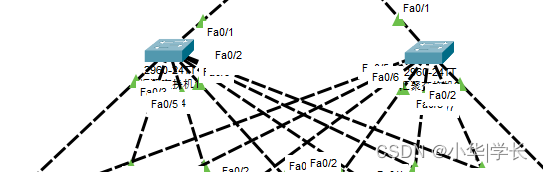
图5.2汇聚层设计
汇聚层设备不但分担了核心设备的部分压力,同时提高了网络的安全性。本实施方案从网络运行的稳定性、安全性及易于维护性出发进行设计,以满足客户需求。园区网可基本保持原有的二层网络架构,并在自己的园区网中使用专用IP地址块,楼层之间采用千兆光纤相连,建议划分为若干个子网,也可以划分为多个VLAN,以隔离广播流量,提高网络工作效率,并提高安全性。
交换机的网络扩展主要体现在两个方面:一是用于与下级交换机连接的端口,另一个是用于连接后续添加的工作站用户。与下级交换机连接方面,一般是通过高带宽端口进行的,毕竟下级交换机所连用户都是通过这个端口进行的。如果交换机提供了Uplink(级联)端口,则直接用这个端口即可,因为它本身就是一个经过特殊处理的端口,其可利用的背板带宽比一般的端口宽。但如果没有级联端口,则只能通过普通端口进行了,这时为了确保下级交换机所连用户的连接性能,最好选择一个较高带宽的端口。本示例中可以留下一个干兆位端口用于扩展连接,当然在实际工作中,这个高带宽端口还是可以得到充分利用的,只是到需要时能重新空余下来即可。
在企业网中,汇聚层是核心层和接入层之间的分界点。它能帮助定义和区分核心层。汇聚层的功能是对网络的边界进行定义。对数据包/帧的处理应该在这一层完成。在中小型企业的网络环境中,汇聚层设计了两台交换机,与接入交换机两两互联,物理链路冗余,某台汇聚交换机故障时只需要等待STP生成树收敛时间完成,保证用户的办公和上网体验。
汇聚层:汇聚层是网络接入层和核心层的“中介”,就是在工作站接入核心层前先做汇聚,以减轻核心层设备的负荷。汇聚层具有实施策略、安全、工作组接入、虚拟局域网(VLAN)之间的路由、源地址或目的地址过滤等多种功能。在汇聚层中,应该选用支持三层交换技术和VLAN的交换机,以达到网络隔离和分段的目的。
5.3接入层设计

图5.3接入层设计
接入层向本地网段提供工作站接入。交换机端口总数不等于可连接的工作站用户数,因为交换机中的一些端口还要用来连接那些不是工作站的网络设备,如服务器、下级交换机、网络打印机、路由器、网关、网桥等。假设,网络中有一台专门的服务器、一台宽带路由器和一台网络打印机,所以网络中可连接的工作站用户总数就为26(24个1 O/1 00Mbps端口+2个1 O/1 00/1 00Mbps端口)一3=23 个。如果要保留一个端口用于网络扩展(在小型网络中保留一个扩展端口基本上可以满足,因为在一般的交换机上还有一个用于级联下级交换机的级联端口Uplink),则实际上可连接的最多工作站用户数为22个。在接入层中,减少同一网段的工作站数量,能够向工作组提供高速带宽。接入层因为部署在楼层弱电间内,需要注意的就是各个部门之间的VLAN需要注意划分。
5.3 关键性技术及难点
这种扩展型星型网络比起前面介绍的小型星型网络要复杂得多,在其中涉及到的网络技术也复杂许多。下面是设计这类网络结构的基本思路。
采用白上而下的分层结构设计
首先确定的是核心交换机的连接,然后是会聚层交换机的连接。再次是边缘层的交换机连接。
把关键设备冗余连接在两台核心交换机上
要实现核心交换机负载均衡和冗余配置,最好对核心交换机之问、核心交换机与骨干层交换机之间,以及核心交换机与关键设备之间进行均衡和冗余连接和配置。
连接其他网络设备
把关键用户的工作站和大负荷网络打印机等设备连接在核心交换机,或者会聚层交换机的普通端口上;把工作负荷相对较小的普通工作站用户连接在边缘交换机上。
本项目采用的关键技术为NAT地址转换、OSPF动态路由协议以及DHCP动态主机协议的地址下发和STP生成树的链路冗余。
主要难点在于互联网接入路由器对于静态映射需要格外注意,端口一一对应,需要精确到某个协议的某个端口。
5.4 存在问题和解决办法
就是STP生成树的根桥问题,需要了解生成树选举规则,并根据规则和最优路径来指定根设备,或者手动对设备指定根桥来确保网络转发正常,避免MAC地址抖动等影响网络体验感的事件发生
第6章 系统测试
6.1 配置实施
6.1.1 出口路由器

图5.1 出口路由器
PNAT与静态NAT配置:
access-list 1 permit any //创建供NAT调用的ACL列表
ip nat inside source list 1 interface GigabitEthernet0/2 overload //配置源地址转换
ip nat inside source static tcp 10.10.200.80 80 188.245.202.1 80 //内部WEB服务器映射互联网
出口路由器作为互联网接入设备,对于整个局域网网络来说是至关重要的一个设备,它既负责着内部网络的上网转换,又对外部访问内部服务器的业务做了一个目的转换,如果出口路由器宕机,那么将造成整个局域网无法访问互联网,企业发布在公网上的业务自然也是会中断的。
6.1.2 核心交换机
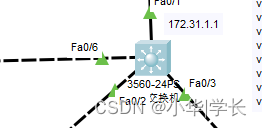
图6.2 核心交换机
DHCP地址池配置:
ip dhcp pool 10 //创建地址池
network 10.10.0.0 255.255.255.0 //设置DHCP下发网段
default-router 10.10.0.254 //指定网关
dns-server 10.10.200.53 //指定下发DNS地址
交换机开启路由功能:
ip routing
核心交换机对于整个局域网来说就是一个中转设备,内部终端设备的网关部署在核心上,核心交换机通过内部交换实现了各个网段的互联互通,并且与路由器之间配置了OSPF的骨干区域路由,让本地网段可自动发送至DR让路由器学习,无需人工手动进行配置,方便了运维人员运维。
6.1.3 汇聚交换机
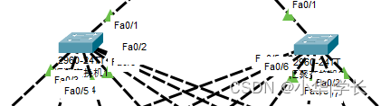
图6.3 汇聚交换机。
接口配置:
interface ran FastEthernet0/1-10
sw tr en do
sw mo trunk
汇聚层设备主要与核心和接入层线路都是交叉互联的,通过STP生成树协议的特点来对网络环路进行破环,汇聚承接了所有接入交换机的流量,并且链路备份可让网络具有更高的可靠性。
6.1.4接入交换机
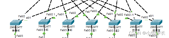
图6.4 接入交换机
销售部交换机接口配置:
interface FastEthernet0/1
switchport mode trunk
interface FastEthernet0/2
switchport mode trunk
interface FastEthernet0/3
switchport access vlan 10
接入层设备是终端接入的信息点了,设备的端口数多,设置两条上联线做主备来实现冗余,上联口配置trunk并允许VLAN通过,终端则就按需配置相应的VLAN号,让终端可接入网络中。
6.1.5 服务器配置
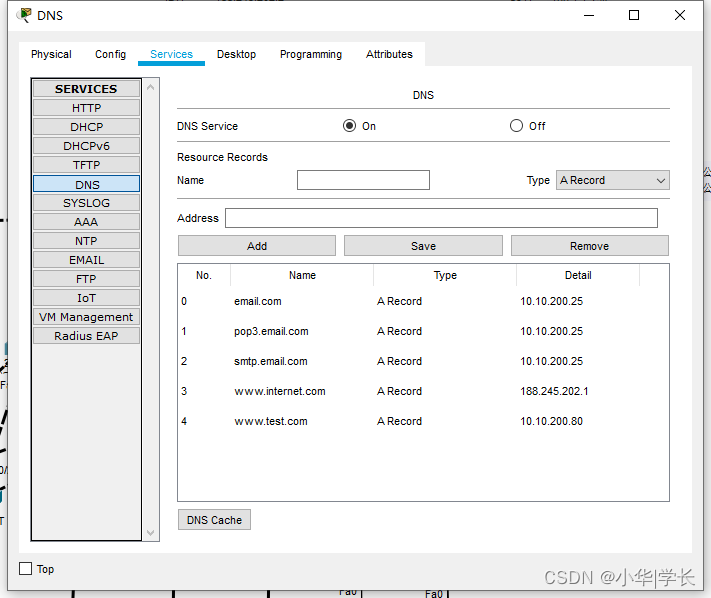
图6.5 DNS服务器配置
DNS服务器的主要作用就是在于域名解析,设立一个域名通过与IP地址的对应关系配置,实现访问域名自动解析到相应的IP地址,本地DNS服务器配置了邮件服务器的解析和WEB服务器的内网地址解析和外网地址解析。

图6.6 WEB服务器配置
局域网的内部搭建了WEB服务器,服务器对内部和外部开启HTTP功能,并且按需修改index首页内容,通过DNS的解析和设备的公网发布让局域网以及互联网用户打开WEB服务器都能同步到此项内容。

图6.7 email服务器配置
邮件服务器设置域名为email.com,创建usre1和user2两个账号,开启服务后,通过内网的DNS服务器解析此域名就可以通过账户密码登录的方式正常的连接到邮件服务器来进行收发邮件。
6.2 连通性测试
6.2.1 终端DHCP自动获取
终端通过核心交换机的DHCP地址池的下发自动获取到了IP、网关和DNS。
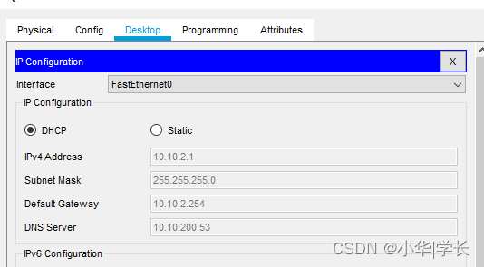
图6.8 DHCP自动获取
6.2.2 部门之间互访测试
销售部ping人事部和办公室1测试,返回结果正常。
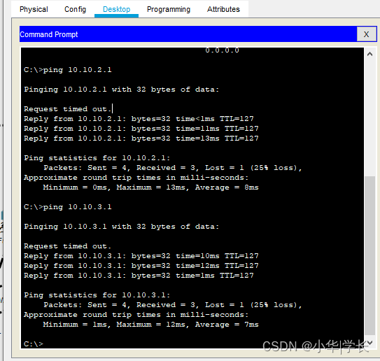
图6.9 局域网互访
6.2.3 OSPF效果测试
核心交换机上查看OSPF的邻接关系,返回结果为FULL。

图6.10 OSPF邻居建立成功
路由器查看路由器,发现OSPF的路由已经成功写进路由表里了,与邻居的关系建立和路由学习正常。

图6.11 路由器学习到的OSPF路由
6.2.4 终端上网测试
人事部访问互联网的PC地址,测试正常。
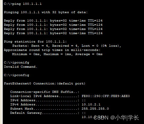
人事部访问互联网正常
路由器监测到人事部访问互联网,在设备上做了源地址转换。
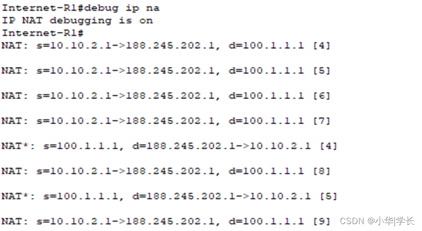
路由器nat信息
6.2.5 email邮件服务器测试
经理室设置user1,财务部配置user2的邮箱信息,通过经理室发送邮件到[email protected],财务部正常接收邮件,测试正常。
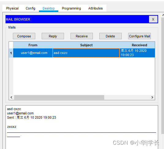
经理室发送邮件财务部接收
6.2.6 静态NAT访问测试
互联网PC通过设置内部映射出公网的DNS地址,成功解析了域名为www.internet.com的网站服务器。

互联网PC通过内部DNS解析访问WEB服务器
第7章 总结
本次设计的题目为基于静态NAT的中小企业服务器网络端口映射与实现。通过本次的毕业设计,开始时,我对毕业设计和论文的写法做法都一头雾水,完全不知道要从哪开始动手,后来,通过导师和同学的帮助,让我对毕业设计和论文所需了解得知识越来越丰富,再加上资料得查询,对网络知识的不断加深。在搜集资料后,我在电脑中都进行分类的整理,然后针对自己不同部分的写作内容进行归纳和总结。尽量使我的资料和论文的内容符合,这有利于论文的撰写。然后及时拿给老师进行沟通,听取老师的意见后再进行相关的修改。老师的意见总是很宝贵的,可以很好的指出我的资料收集的不足以及需要什么样的资料来完善文章。一步一脚印的对毕业设计进行设计、搭建、调试、测试再到最后的设计完成。这一阶段的学习让我对网络这个IT方向更加的了解和深入,也对这个行业有了更深的研究,但是根据目前所学的技术,本课题的设计还存在很多不够成熟的地址,我会在接下来的学习和工作中,对此次设计不断的完善和改进。不足之处如下:
- 发现局域网的安全系数不够高,网络安全性保障不高,没办法实现全面的阻止互联网的一切可疑信息攻击以及恶意的DOS请求,也无法对局域网内的终端采取防病毒措施。
- 未实现对内部人员使用的网络应用进行管控,因此增加了网络安全的不确定性。
附 录
附录1:核心源代码
Vlan 10 //创建VLAN10
Vlan 11 //创建VLAN11
Vlan 12 //创建VLAN12
Vlan 13 //创建VLAN13
Vlan 14 //创建VLAN14
Vlan 15 //创建VLAN15
Vlan 16 //创建VLAN16
Vlan 254 //创建VLAN254
ip dhcp pool 10 //创建DHCP地址池
network 10.10.0.0 255.255.255.0 //地址池网段
default-router 10.10.0.254 //网关地址
dns-server 10.10.200.53 //DNS地址
ip dhcp pool 11 //创建DHCP地址池
network 10.10.1.0 255.255.255.0 //地址池网段
default-router 10.10.1.254//网关地址
dns-server 10.10.200.53 //DNS地址
ip dhcp pool 12 //创建DHCP地址池
network 10.10.2.0 255.255.255.0//地址池网段
default-router 10.10.2.254//网关地址
dns-server 10.10.200.53 //DNS地址
ip dhcp pool 13 //创建DHCP地址池
network 10.10.3.0 255.255.255.0//地址池网段
default-router 10.10.3.254//网关地址
dns-server 10.10.200.53 //DNS地址
ip dhcp pool 14 //创建DHCP地址池
network 10.10.4.0 255.255.255.0//地址池网段
default-router 10.10.4.254//网关地址
dns-server 10.10.200.53 //DNS地址
ip dhcp pool 15 //创建DHCP地址池
network 10.10.5.0 255.255.255.0//地址池网段
default-router 10.10.5.254//网关地址
dns-server 10.10.200.53 //DNS地址
ip dhcp pool 16 //创建DHCP地址池
network 10.10.6.0 255.255.255.0//地址池网段
default-router 10.10.6.254//网关地址
dns-server 10.10.200.53 //DNS地址
ip routing //开启路由功能
spanning-tree mode pvst //STP模式
spanning-tree vlan 10-4094 priority 24576 //STP优先级设置
interface FastEthernet0/1 //进入接口
no switchport //关闭交换模式
ip address 172.31.1.1 255.255.255.0 //设置IP
interface FastEthernet0/2 //进入接口
switchport trunk encapsulation dot1q //接口封装dot1q
switchport mode trunk //设置trunk口
!
interface FastEthernet0/3 //进入接口
switchport trunk encapsulation dot1q//接口封装dot1q
switchport mode trunk //设置trunk口
!
interface FastEthernet0/4 //进入接口
switchport trunk encapsulation dot1q//接口封装dot1q
switchport mode trunk //设置trunk口
!
interface FastEthernet0/5 //进入接口
switchport trunk encapsulation dot1q//接口封装dot1q
switchport mode trunk //设置trunk口
!
interface FastEthernet0/6 //进入接口
switchport trunk encapsulation dot1q//接口封装dot1q
switchport mode trunk //设置trunk口
interface Vlan10 //进入VLAN接口
ip address 10.10.0.254 255.255.255.0 //配置VLAN地址
!
interface Vlan11//进入VLAN接口
ip address 10.10.1.254 255.255.255.0 //配置VLAN地址
!
interface Vlan12//进入VLAN接口
ip address 10.10.2.254 255.255.255.0 //配置VLAN地址
!
interface Vlan13//进入VLAN接口
ip address 10.10.3.254 255.255.255.0 //配置VLAN地址
!
interface Vlan14//进入VLAN接口
ip address 10.10.4.254 255.255.255.0 //配置VLAN地址
!
interface Vlan15//进入VLAN接口
ip address 10.10.5.254 255.255.255.0 //配置VLAN地址
!
interface Vlan16//进入VLAN接口
ip address 10.10.6.254 255.255.255.0 //配置VLAN地址
!
interface Vlan254//进入VLAN接口
ip address 10.10.200.254 255.255.255.0 //配置VLAN地址
!
router ospf 1 //创建OSPF
network 172.31.1.0 0.0.0.255 area 0 //宣告本地网段设置区域为0
network 10.10.0.0 0.0.0.255 area 0 //宣告本地网段设置区域为0
network 10.10.200.0 0.0.0.255 area 0 //宣告本地网段设置区域为0
network 10.10.1.0 0.0.0.255 area 0//宣告本地网段设置区域为0
network 10.10.2.0 0.0.0.255 area 0//宣告本地网段设置区域为0
network 10.10.3.0 0.0.0.255 area 0//宣告本地网段设置区域为0
network 10.10.4.0 0.0.0.255 area 0//宣告本地网段设置区域为0
network 10.10.5.0 0.0.0.255 area 0//宣告本地网段设置区域为0
network 10.10.6.0 0.0.0.255 area 0//宣告本地网段设置区域为0
路由器:
interface GigabitEthernet0/0 //进入接口
ip address 172.31.1.2 255.255.255.0 //配置接口IP
ip nat inside //nat内网口
interface GigabitEthernet0/2 //进入接口
ip address 188.245.202.1 255.255.255.0 //设置接口IP
ip nat outside //设置nat外网口
router ospf 1 //创建OSPF
network 172.31.1.0 0.0.0.255 area 0 //宣告内网网段并设置区域0
default-information originate //通告缺省路由
ip nat inside source list 1 interface GigabitEthernet0/2 overload //源地址转换设置为G0/2出接口地址
ip nat inside source static tcp 10.10.200.80 80 188.245.202.1 80 //服务器映射80端口至互联网
ip nat inside source static tcp 10.10.200.53 53 188.245.202.1 53
//DNS映射53端口至互联网
ip nat inside source static udp 10.10.200.53 53 188.245.202.1 53
//DNS映射53端口至互联网
ip route 0.0.0.0 0.0.0.0 188.245.202.2 //默认路由配置
access-list 1 permit any //ACL 1 允许所有流量