Camera calibration
-
-
- 01. Camera calibration
- 02. OpenCV function and Zhang Zhengyou’s calibration method
-
- 2.1. Camera calibration steps
- 2.2. Camera calibration related functions
-
- 2.2.1 Extract corner points --- findChessboardCorners
- 2.2.2 Sub-pixel corner point extraction 1--- find4QuadCornerSubpix
- 2.2.3 Sub-pixel corner point extraction 2--- cornerSubPix
- 2.2.4 Draw interior corners --- drawChessboardCorners
- 2.2.5 Camera calibration --- calibrateCamera
- 2.2.6 Calibration evaluation --- projectPoints
- 2.2.7 View calibration results (two methods)
- 03. Qt+OpenCV program
- 04. Running screenshots
-
01. Camera calibration
Machine vision uses camera imaging to realize the measurement, positioning, reconstruction and other processes of three-dimensional scenes. It is also a process of using two-dimensional images to perform three-dimensional inference. The world we live in is three-dimensional, and images or photos are two-dimensional. We can think of the camera as a function, the input is a three-dimensional scene, and the output is a two-dimensional image. Normally, the process from three dimensions to two dimensions is irreversible.
If we can find a suitable mathematical model to approximate the above three-dimensional to two-dimensional process, and then find the inverse function of this mathematical model, we can realize the inverse process of two-dimensional to three-dimensional.
That is: use a simple mathematical model to express the complex imaging process, and find the inverse process of imaging.
Why use camera calibration?
As we know above, three-dimensional to two-dimensional is through the principle of imaging. In this process, the imaged image will be very different from the original image due to the factory parameters or distortion parameters of the camera. Calibration is to determine these parameters, and then the actual processing will be done. When working, correct the image through these parameters.
Parameters involved in calibration:
| Internal parameter matrix | External parameter matrix | Distortion parameters |
|---|---|---|
| f/dx,f/dy,u0,v0 | Camera pose, translation, rotation | k1,k2,p1,p2,k3 |
Among the distortion parameters, k1, k2, and k3 represent the radial distortion parameters, and p1 and p2 represent the tangential distortion parameters.
The external parameter matrix is related to many factors such as camera placement, so it is ignored in non-specific applications.
Conclusion: Camera calibration is the process of determining the internal and external parameters and distortion parameters of the camera.
Common methods for camera calibration:
| Calibration method | advantage | shortcoming | Common methods |
|---|---|---|---|
| Camera self-calibration method | High flexibility and can be calibrated online | Low accuracy and poor robustness | Hierarchical stepwise calibration, based on Kruppa equation |
| Active vision camera calibration method | No need to calibrate objects, simple algorithm, high robustness | High cost and expensive equipment | Active systems control cameras to make specific movements |
| calibration method | Can be used with any camera model, high accuracy | Requires calibration materials and complex algorithms | Tsai two-step method, Zhang Zhengyou calibration method (all methods in this article) |
Robustness : refers to the characteristics of a control system that maintains certain performance under certain (structure, size) parameter perturbations.
There is also another official statement for the above three types: linear calibration method, nonlinear optimization calibration method, and two-step method.
To be honest, I am very confused about the theory of vision. If you don’t understand it, just look it up and get into the code.
02. OpenCV function and Zhang Zhengyou’s calibration method
2.1. Camera calibration steps
Using OpenCV for Zhang Zhengyou calibration, the summary is as follows:
- Prepare calibration pictures
- Extract corner information from each image
- Further extract sub-pixel corner information for each image
- Draw interior corners on the checkerboard (displayed, optional)
- Camera calibration
- Evaluate calibration results
- View calibration results/use calibration results to correct camera images.
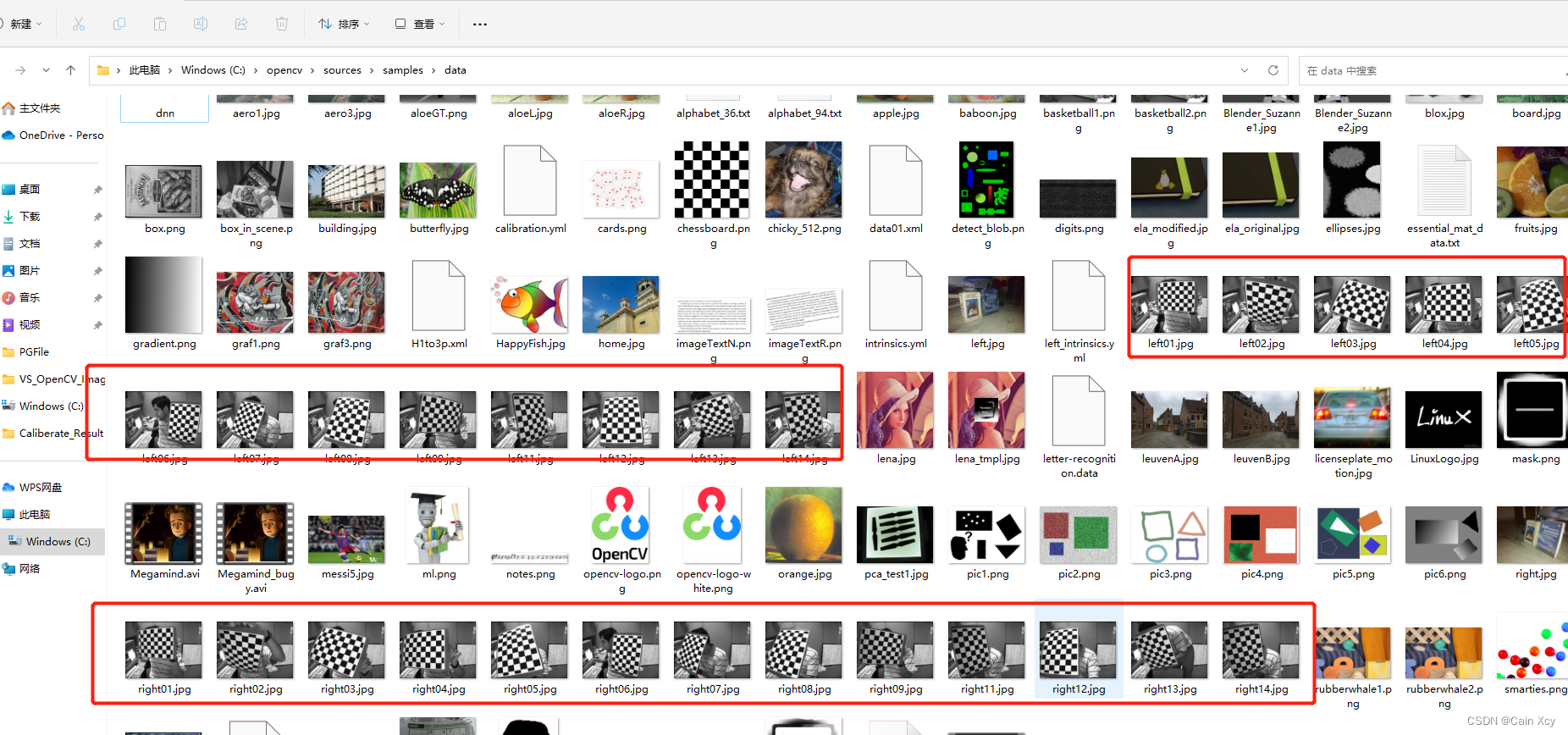
Try to use a checkerboard grid for calibration pictures. When using OpenCV, you can directly use the included pictures. The path is under the installation directory, as follows:
If not, you can draw one yourself. The drawing procedure is as follows:
// 生成棋盘格(demo)
void CreateGridironPattern()
{


    // 单位转换
    int dot_per_inch = 108;
    /*
    * 这里以我惠普 光影精灵9的参数计算如下:
    *  公式: DPI = 1920 / sqrt(15.6 ^ 2 + (1920 / 1080 * 15.6)^2)
    *  sqrt(15.6 ^ 2 + (1920 / 1080 * 15.6)^2) ≈ 17.76
    */

    double cm_to_inch = 0.3937;   // 1cm = 0.3937inch
    double inch_to_cm = 2.54;    //  1inch = 2.54cm( 1 英寸 = 2.54 厘米 是一个国际公认的单位)
    double inch_per_dot = 1.0 / 96.0;

    // 自定义标定板
    double blockSize_cm = 1.5;  // 方格尺寸: 边长1.5cm的正方形
    // 设置横列方框数目
    int blockcol = 10;
    int blockrow = 8;

    int blockSize = (int)(blockSize_cm / inch_to_cm * dot_per_inch);
    cout << "标定板尺寸: " << blockSize << endl;

    int imageSizeCol = blockSize * blockrow;
    int imageSizeRow = blockSize * blockcol;

    Mat chessBoard(imageSizeCol, imageSizeRow, CV_8UC3, Scalar::all(0));
    unsigned char color = 0;

    for (int i = 0; i < imageSizeRow; i = i + blockSize) {


        color = ~color; // 将颜色值取反,如果开始为0,取反后为255(即黑白互换)
        for (int j = 0; j < imageSizeCol; j = j + blockSize) {


            Mat ROI = chessBoard(Rect(i, j, blockSize, blockSize));
            ROI.setTo(Scalar::all(color));
            color = ~color;
        }
    }

    imshow("chess board", chessBoard);
    imwrite("chessBard.jpg", chessBoard);

    waitKey(0);
    return;
}
Then take photos, preferably 10 to 20 photos (use a calibrated camera to take photos).
2.2. Camera calibration related functions
2.2.1 Extract corner points—findChessboardCorners
Function prototype:
CV_EXPORTS_W bool findChessboardCorners( InputArray image, Size patternSize, OutputArray corners,
                                         int flags = CALIB_CB_ADAPTIVE_THRESH + CALIB_CB_NORMALIZE_IMAGE );
Parameter explanation:
image: The captured checkerboard Mat image must be an 8-bit grayscale or color image.patternSize: The number of rows and columns of the inner corner points on each checkerboard. Generally, the number of rows and rows should not be the same, so that the subsequent program to be determined can identify the direction of the calibration board.corners: Used to store the detected inner corner point image coordinates, generally represented by a vector whose elements are Point2f, such as:vector<Point2f> image_points_buf.
2.2.2 Sub-pixel corner point extraction 1—find4QuadCornerSubpix
Function prototype:
CV_EXPORTS_W bool find4QuadCornerSubpix( InputArray img, InputOutputArray corners, Size region_size );
Parameter explanation:
img: The input Mat matrix is preferably an 8-bit grayscale image, which has higher detection efficiency.corners: The initial corner point coordinate vector is also used as the output of the sub-pixel coordinate position, so floating point data is generally represented by a vector whose elements are Point2f/Point2d, such as:vector<Point2f> imagePointBuf.region_size: The size of the corner search window.
2.2.3 Sub-pixel corner point extraction 2— cornerSubPix
Function prototype:
CV_EXPORTS_W void cornerSubPix( InputArray image, InputOutputArray corners,
                                Size winSize, Size zeroZone,
                                TermCriteria criteria );
Parameter explanation:
image: The input Mat matrix is preferably an 8-bit grayscale image, which has higher detection efficiency.corners: The initial corner point coordinate vector is also used as the output of the sub-pixel coordinate position, so it needs to be floating point data. It is generally represented by a vector whose elements are Point2f/Point2d, such as:vector<Point2f> imagePointBuf.winSize: The size is half of the search window.zeroZone: Half the size of the dead zone, which is an area where the summation operation is not performed on the central position of the search area. It is used to avoid certain possible singularities in the autocorrelation matrix. When the value is (-1, -1), it means there is no dead zone.criteria: Define the termination condition of the iterative process of finding corner points, which can be a combination of the number of iterations and the corner point accuracy.
I read online that the experts said that the deviation of the results measured by the two functions is basically controlled within 0.5 pixels.
2.2.4 Draw interior corners—drawChessboardCorners
Function prototype:
CV_EXPORTS_W void drawChessboardCorners( InputOutputArray image, Size patternSize,
                                         InputArray corners, bool patternWasFound );
Parameter explanation:
image: 8-bit grayscale or color image.patternSize: The number of rows and columns of interior corner points on each calibrated chessboard.corners: The initial corner point coordinate vector is also used as the output of the sub-pixel coordinate position, so it needs to be floating point data, generally represented by a vector whose elements are Pointf2f/Point2d:vector<Point2f> iamgePointsBuf.patternWasFound: Flag bit, used to indicate whether the defined inner corner points of the chessboard have been completely detected. true means that they have been completely detected. The function will use straight lines to connect all the inner corner points in sequence. As a whole, false means that there are undetected ones. Internal corner point, at this time the function will mark the detected internal corner point with a (red) circle.
2.2.5 Camera calibration— calibrateCamera
Function prototype:
CV_EXPORTS_W double calibrateCamera( InputArrayOfArrays objectPoints,
                                     InputArrayOfArrays imagePoints, Size imageSize,
                                     InputOutputArray cameraMatrix, InputOutputArray distCoeffs,
                                     OutputArrayOfArrays rvecs, OutputArrayOfArrays tvecs,
                                     int flags = 0, TermCriteria criteria = TermCriteria(
                                        TermCriteria::COUNT + TermCriteria::EPS, 30, DBL_EPSILON) );
Parameter explanation:
- objectPoints: It is a three-dimensional point in the world coordinate system. When using it, you should enter the vector of a three-dimensional coordinate point, that is. You need to calculate (initialize) the
vector<vector<Point3f>> object_pointsworld coordinate of each interior corner point based on the size of a single black matrix on the checkerboard. . - imagePoints: The image coordinate point corresponding to each interior corner point. Like objectPoints,
vector<vector<Point2f>> image_points_seqa variable in the form should be entered. - imageSize: It is the pixel size of the image. This parameter needs to be used when calculating the internal parameters and distortion matrix of the camera.
- cameraMatrix: is the internal parameter matrix of the camera. Just enter one
Mat cameraMatrix, such as:Mat cameraMatrix=Mat(3,3,CV_32FC1,Scalar::all(0)). - distCoeffs: is the distortion matrix. Enter one
Mat distCoeffs = Mat(1,5CV_32FC1,Scalar::all(0)). - rvercs: For the rotation vector, a vector of Mat type should be input, that is
vector<Mat> rvecs. - tvecs: For the translation vector, a vector of Mat type should be input, that is
vector<Mat> tvecs. - flags: It is the algorithm used during calibration, with the following parameters:
| parameter | explain |
|---|---|
| CV_CALIB_USE_INTRINSIC_GUESS | When using this parameter, there should be estimated values of fx, fy, u0, v0 in the cameraMatrix matrix. Otherwise, the center point of the (u0, v0) image will be initialized, and fx, fy will be estimated using least squares |
| CV_CALIB_FIX_PRINCIPAL_POINT | The optical axis point is fixed during optimization. When the CV_CALIB_USE_INTRINSIC_GUESS parameter is set, the optical axis point will remain at the center or some input value |
| CV_CALIB_FIX_ASPECT_RATIO | The ratio of fx/fy is fixed, and only fy is used as a variable variable for optimization calculation. When CV_CALIB_USE_INTRINSIC_GUESS is not set, fx and fy will be ignored. Only the fx/fy ratio is used in the calculations |
| CV_CALIB_ZERO_TANGENT_DIST | Set the tangential distortion parameters (p1, p2) to zero |
| CV_CALIB_FIX_K1,…,CV_CALIB_FIX_K6 | The corresponding radial distortion remains unchanged in the optimization |
| CV_CALIB_RATIONAL_MODEL | Calculate the three distortion parameters k4, k5, and k6. If not set, only the other 5 distortion parameters will be calculated. |
- criteria: Optimal iteration termination condition setting.
Before using this function for calibration operation, it is necessary to initialize the position coordinates of the spatial coordinate system of each interior corner point on the chessboard. The result of the calibration is to generate the camera's internal parameter matrix cameraMatrix, the camera's five distortion coefficients distCoeffs, and each image Each will generate its own translation vector and rotation vector.
2.2.6 Calibration evaluation—projectPoints
Function prototype:
CV_EXPORTS_W void projectPoints( InputArray objectPoints,
                                 InputArray rvec, InputArray tvec,
                                 InputArray cameraMatrix, InputArray distCoeffs,
                                 OutputArray imagePoints,
                                 OutputArray jacobian = noArray(),
                                 double aspectRatio = 0 );
- objectPoints: are the three-dimensional point coordinates in the camera coordinate system.
- rvec: is the rotation vector. Each image has its own rotation vector.
- tvec: is the translation vector, each image has its own translation vector.
- cameraMatrix: is the internal parameter matrix of the camera obtained.
- distCoeffs: is the distortion matrix of the camera.
- imagePoints: The coordinate point on the image corresponding to each interior corner point.
- jacobian: is the Jacobian determinant.
- aspectRatio: An optional parameter related to the photosensitive unit of the camera sensor. If set to non-0, the function defaults to a fixed dx/dy of the photosensitive unit, and the Jacobian matrix will be adjusted accordingly.
2.2.7 View calibration results (two methods)
- Method 1: Use the two functions initUndistortRectifyMap and remap to implement it.
2.2.7.1 initUndistortRectifyMap and remap
函数原型:
CV_EXPORTS_W
void initUndistortRectifyMap(InputArray cameraMatrix, InputArray distCoeffs,
                             InputArray R, InputArray newCameraMatrix,
                             Size size, int m1type, OutputArray map1, OutputArray map2);
Parameter explanation:
- cameraMatrix: is the internal parameter matrix of the camera obtained previously.
- distCoeffs: is the previously obtained camera distortion matrix coefficient.
- R: Optional input, which is the rotation matrix between the first and second camera coordinates.
- newCameraMatrix: The input corrected 3x3 camera matrix.
- size: The size of the image captured by the camera without distortion.
- m1type: Defines the data type of map1, which can be CV_32FC1 or CV_16SC2.
- map1: Output X coordinate remapping parameters.
- map2: Output Y coordinate remapping parameters.
Function prototype:
CV_EXPORTS_W void remap( InputArray src, OutputArray dst,
                         InputArray map1, InputArray map2,
                         int interpolation, int borderMode = BORDER_CONSTANT,
                         const Scalar& borderValue = Scalar());
Parameter explanation:
- src: input parameter, representing the distorted original image.
- dst: The corrected output image has the same type and size as the input image.
- map1, map2: mapping of X and Y coordinates.
- interpolation: Define the interpolation method of the image.
- borderMode: Defines the filling method of the border.
- Method 2: Use the undistort function to implement.
2.2.7.2 undistort
Function prototype:
CV_EXPORTS_W void undistort( InputArray src, OutputArray dst,
                             InputArray cameraMatrix,
                             InputArray distCoeffs,
                             InputArray newCameraMatrix = noArray() );
Parameter explanation:
- src: input parameter, representing the distorted original image.
- dst: Output parameter, representing the corrected image, which has the same type and size as the input image.
- cameraMatrix: The camera internal parameter matrix obtained previously.
- distCoeffs: The previously obtained distortion matrix coefficient of the camera.
- newCameraMatrix: The default is consistent with cameraMatrix.
According to tests by online experts, method one is more efficient than method two, and is recommended.
03. Qt+OpenCV program
Regarding the use of OpenCV in QT, I won’t go into details here. For details, you can check previous blogs.
.prodocument
#-------------------------------------------------
#
# Project created by QtCreator 2023-07-11T14:44:57
#
#-------------------------------------------------

QT       += core gui

greaterThan(QT_MAJOR_VERSION, 4): QT += widgets

TARGET = CalibrateDemo
TEMPLATE = app

# The following define makes your compiler emit warnings if you use
# any feature of Qt which has been marked as deprecated (the exact warnings
# depend on your compiler). Please consult the documentation of the
# deprecated API in order to know how to port your code away from it.
DEFINES += QT_DEPRECATED_WARNINGS

# You can also make your code fail to compile if you use deprecated APIs.
# In order to do so, uncomment the following line.
# You can also select to disable deprecated APIs only up to a certain version of Qt.
#DEFINES += QT_DISABLE_DEPRECATED_BEFORE=0x060000    # disables all the APIs deprecated before Qt 6.0.0

CONFIG += c++11

SOURCES += \
        main.cpp \
        mainwindow.cpp

HEADERS += \
        mainwindow.h

FORMS += \
        mainwindow.ui

INCLUDEPATH += \
            C:\opencv\install\install\include \

LIBS += \
        C:\opencv\install\lib\libopencv_*.a \

# Default rules for deployment.
qnx: target.path = /tmp/$${

    TARGET}/bin
else: unix:!android: target.path = /opt/$${

    TARGET}/bin
!isEmpty(target.path): INSTALLS += target
mainwindow.hdocument
#ifndef MAINWINDOW_H
#define MAINWINDOW_H

#include <opencv2/opencv.hpp>
#include <opencv2/core/core.hpp>
#include <QMainWindow>
#include <iostream>
#include <fstream>
#include <io.h>
#include <QFileDialog>
#include <QDebug>
#include <vector>
#include <QLabel>
#include <QVBoxLayout>
#include <QThread>

using namespace std;
using namespace cv;

#define CALIBRATERESULTFILE "CalibrateResult.txt"

namespace Ui {


class MainWindow;
}

class MainWindow : public QMainWindow
{


    Q_OBJECT

public:
    explicit MainWindow(QWidget *parent = nullptr);
    ~MainWindow();

private slots:
    void on_pushButton_LoadImage_clicked();

    void on_pushButton_SaveResult_clicked();

    void on_pushButton_StartCalibrate_clicked();

    void on_pushButton_AppraiseCalibrate_clicked();

public:
    // QT图像 to openCV图像  和  openCV图像 to QT图像
    QImage MatToQImage(Mat const& src);
    Mat QImageToMat(QImage const& src);

    void showCameraMatrix(Mat const& data);  // 显示内参矩阵
    void showDistCoeffs(Mat const& data);   // 显示畸变系数

private:
    Ui::MainWindow *ui;

    // 保存不同图片标定板上角点的三维坐标
    vector<vector<Point3f>> object_points;
    // 缓存每幅图像上检测到的角点
    vector<Point2f> image_points_buf;
    // 保存检测到的所有角点
    vector<vector<Point2f>> image_points_seq;
    // 相机内参数矩阵
    cv::Mat cameraMatrix;
    // 相机的畸变系数
    cv::Mat distCoeffs;
    // 每幅图像的平移向量
    vector<cv::Mat> tvecsMat;
    // 每幅图像的旋转向量
    vector<cv::Mat> rvecsMat;
    // 加载标定图片的文件夹
    QString m_strCalibrateFolder;
    // 保存标定结果的文件夹
    QString m_strSaveResultFolder;
    // 写入
    std::ofstream fout;
    // 图像数量
    int image_count = 0;
    // 每幅图像中角点的数量
    vector<int> point_counts;
};

#endif // MAINWINDOW_H
mainwindow.cppdocument
#include "mainwindow.h"
#include "ui_mainwindow.h"

MainWindow::MainWindow(QWidget *parent) :
    QMainWindow(parent),
    ui(new Ui::MainWindow)
{


    ui->setupUi(this);

    // 渲染设置为硬件加速
    ui->label_showMat->setAttribute(Qt::WA_OpaquePaintEvent,true);
    ui->label_showMat->setAttribute(Qt::WA_NoSystemBackground,true);
    ui->label_showMat->setAutoFillBackground(false);

    cameraMatrix = cv::Mat(3,3,CV_32FC1, Scalar::all(0));
    distCoeffs = cv::Mat(1,5,CV_32FC1, Scalar::all(0));
}

MainWindow::~MainWindow()
{


    delete ui;
}

void MainWindow::on_pushButton_LoadImage_clicked()
{


    QString folderPath = QFileDialog::getExistingDirectory(this,QStringLiteral("选择标定图片文件夹"),tr(""),QFileDialog::ShowDirsOnly);
    if(!folderPath.isEmpty()) {


        //文件夹不为空
        m_strCalibrateFolder = folderPath;
    } else {


        qDebug()<< "未选择任何文件夹";
        return;
    }

    // 将加载的路径显示在界面
    ui->lineEdit_CalibrateImagePath->setText(folderPath);
    // 设置文字左对齐
    ui->lineEdit_SaveResultPath->setAlignment(Qt::AlignLeft);
}

void MainWindow::on_pushButton_SaveResult_clicked()
{


   QString folderPath = QFileDialog::getExistingDirectory(this,QStringLiteral("选择保存结果文件夹"),tr(""),QFileDialog::ShowDirsOnly);
   if(folderPath.isEmpty()) {


       qDebug()<< "未选择任何文件夹";
       return;
   }

   m_strSaveResultFolder = folderPath;
   // 设置路径到界面
   ui->lineEdit_SaveResultPath->setText(folderPath);
   // 左对齐
   ui->lineEdit_SaveResultPath->setAlignment(Qt::AlignLeft);
}

void MainWindow::on_pushButton_StartCalibrate_clicked()
{


    // 保存标定结果的txt
    QString strResult = m_strSaveResultFolder + QString("/%1").arg(CALIBRATERESULTFILE);
    fout.open(strResult.toStdString().c_str());

    // 1、加载标定图片
    vector<QString> imageNames;
    QDir dir(m_strCalibrateFolder);
    QStringList fileNames = dir.entryList(QDir::Files | QDir::NoDotAndDotDot, QDir::Name);

    foreach(const QString& fileName, fileNames) {


        QString filePath = dir.filePath(fileName);
        imageNames.push_back(filePath);  // 将完整的路径添加到图片路径容器
    }

    // 2、分别对每张图片进行角点提取
    Size image_size;      // 图像尺寸
    Size board_size = Size(9,6);  // 标定板上每行、列的角点数
    int count = -1;  // 用于存储角点个数

    for(int i = 0; i < imageNames.size(); i++) {


        image_count++;
        // 输出观察
        qDebug()<< "image_count = " << image_count;
        // 输出校验
        qDebug()<< "Check count = " << count;

        // 读取图片
        Mat imageInput = imread(imageNames[i].toStdString().c_str());

        if(image_count == 1) {


            // 读入第一张图片时获取图像宽高信息
            image_size.width = imageInput.cols;
            image_size.height = imageInput.rows;
        }

        // 提取角点
        if(0 == findChessboardCorners(imageInput, board_size, image_points_buf))
        {

    // 未发现角点信息/找不到角点
            qDebug()<< "未发现角点信息";
            return;
        }
        else {


         // 3、对每一张标定图像进行亚像素化处理
            Mat view_gray;
            // 将imageInput转为灰度图像

            cvtColor(imageInput, view_gray, COLOR_RGB2GRAY);
            // 亚像素精准化(对粗提取的角点进行精准化)
            find4QuadCornerSubpix(view_gray,image_points_buf,Size(5,5));
            image_points_seq.push_back(image_points_buf);  // 尾插,保存亚像素角点

         // 4、在棋盘格显示,并在界面刷新图片(显示找到的内角点绘制图片)
            // 在图像上显示角点位置
            drawChessboardCorners(imageInput, board_size, image_points_buf, true);
#if 0
            imshow("Camera Calibration", imageInput);  // 显示图片
            imwrite("Calibration" + to_string(image_count) + ".png", imageInput); // 写入图片
            waitKey(100);  // 暂停0.1s
#else
            QImage tmpImage = MatToQImage(imageInput);
            ui->label_showMat->setPixmap(QPixmap::fromImage(tmpImage.rgbSwapped()));
            ui->label_showMat->show();
            QThread::msleep(100);  // 延时0.1s
            QCoreApplication::processEvents();
#endif

            qDebug()<< "角点提取完成";
        }
    }

    //destroyAllWindows();

    // 5、相机标定
    Size square_size = Size(5,5);

    // 初始化标定板上角点的三维坐标
    int i, j, t;
    for(t = 0; t < image_count; t++) {


        // 图片个数
        vector<Point3f> tempPointSet;
        for(i = 0; i < board_size.height; i++) {


            for(j = 0; j < board_size.width; j++) {


                Point3f realPoint;
                // 假设标定板放在世界坐标系中,z=0的平面上
                realPoint.x = i * square_size.height;
                realPoint.y = j * square_size.width;
                realPoint.z = 0;
                tempPointSet.push_back(realPoint);
            }
        }
        object_points.push_back(tempPointSet);
    }

    // 初始化每幅图像上的角点数量,假定每幅图像中都可以看到完整的标定板
    for(i = 0; i < image_count; i++) {


        point_counts.push_back(board_size.width* board_size.height);
    }

    cv::calibrateCamera(object_points, image_points_seq,image_size,cameraMatrix,distCoeffs,rvecsMat,tvecsMat,0);
    qDebug()<< "标定完成!";

    // 6/7对应下面1/2
}

void MainWindow::on_pushButton_AppraiseCalibrate_clicked()
{


    // 1、对标定结果进行评价
    qDebug() << "开始评价标定结果.....";

    double total_err = 0.0;  // 所有图像的平均误差的总和
    double err = 0.0;  // 每幅图像的平均误差
    vector<Point2f> image_points2;  // 保存重新计算得到的投影点
    qDebug()<< "每幅图像的标定误差: ";
    fout << "每幅图像的标定误差: \n";
    for(int i = 0; i < image_count; i++) {


        vector<Point3f> tempPointSet = object_points[i];
        // 通过得到的摄像机内外参数,对空间的三维点进行重新投影计算,得到新的三维投影点
        projectPoints(tempPointSet, rvecsMat[i], tvecsMat[i], cameraMatrix, distCoeffs, image_points2);

        // 计算新的投影点和旧的投影点之间的误差
        vector<Point2f> tempImagePoint = image_points_seq[i];  // 原先的旧二维点
        Mat tempImagePointMat = Mat(1, tempImagePoint.size(), CV_32FC2);
        Mat image_points2Mat = Mat(1, image_points2.size(), CV_32FC2);
        for(int j = 0; j < tempPointSet.size(); j++) {


            // j对应二维点的个数
            image_points2Mat.at<Vec2f>(0,j) = Vec2f(image_points2[j].x, image_points2[j].y);
            tempImagePointMat.at<Vec2f>(0,j) = Vec2f(tempImagePoint[j].x,tempImagePoint[j].y);
        }

        err = norm(image_points2Mat, tempImagePointMat, NORM_L2);
        total_err += err /= point_counts[i];
        qDebug()<< "第" << i + 1 << "幅图像的平均误差: " << err << "像素";
        fout << "第" << i + 1 << "幅图像的平均误差: " << err << "像素" << endl;
    }

    qDebug()<< "总体平均误差: " << total_err / image_count << "像素";
    fout << "总体平均误差:" << total_err / image_count << "像素" << endl << endl;
    qDebug() << "评价完成!";

    // 2、查看标定结果并保存
    qDebug()<< "开始保存定标结果………………";
    Mat rotation_matrix = Mat(3, 3, CV_32FC1, Scalar::all(0)); /* 保存每幅图像的旋转矩阵 */
    fout << "相机内参数矩阵:" << endl;
    showCameraMatrix(cameraMatrix);
    fout << cameraMatrix << endl << endl;
    fout << "畸变系数:\n";
    showDistCoeffs(distCoeffs);
    fout << distCoeffs << endl;
    for (int i = 0; i < image_count; i++)
    {


        fout << "第" << i + 1 << "幅图像的旋转向量:" << endl;
        fout << rvecsMat[i] << endl;
        /* 将旋转向量转换为相对应的旋转矩阵 */
        Rodrigues(rvecsMat[i], rotation_matrix);
        fout << "第" << i + 1 << "幅图像的旋转矩阵:" << endl;
        fout << rotation_matrix << endl;
        fout << "第" << i + 1 << "幅图像的平移向量:" << endl;
        fout << tvecsMat[i] << endl << endl;
    }
    qDebug()<< "完成保存!";
    fout << endl;
}

QImage MainWindow::MatToQImage(Mat const& src)
{


    Mat temp;  //make the same cv::Mat
    cvtColor(src,temp,COLOR_BGR2RGB); //cvtColor makes a copt, that what i need
    QImage dest((uchar*)temp.data,temp.cols,temp.rows,temp.step,QImage::Format_RGB888);
    dest.bits();  //enforce deep copy, see documentation
    return dest;
}

Mat MainWindow::QImageToMat(QImage const& src)
{


    Mat tmp(src.height(),src.width(),CV_8UC4,(uchar*)src.bits(),src.bytesPerLine());
    Mat result;
    cvtColor(tmp,result,COLOR_RGBA2BGR);
    return result;
}

void MainWindow::showCameraMatrix(const Mat &data)
{


   std::ostringstream ss;
   ss << data;
   std::string strMatrix = ss.str();

   QVBoxLayout* layout = new QVBoxLayout(ui->groupBox_CameraInParam);
   QLabel* label = new QLabel();
   label->setText(QString::fromStdString(strMatrix));
   label->setAlignment(Qt::AlignCenter);
   layout->addWidget(label);
}

void MainWindow::showDistCoeffs(const Mat &data)
{


    std::ostringstream ss;
    ss << data;
    std::string strMatrix = ss.str();

    QVBoxLayout* layout = new QVBoxLayout(ui->groupBox_DistortionParam);
    QLabel* label = new QLabel();
    label->setText(QString::fromStdString(strMatrix));
    label->setAlignment(Qt::AlignCenter);
    label->setWordWrap(true);
    layout->addWidget(label);
}
04. Running screenshots
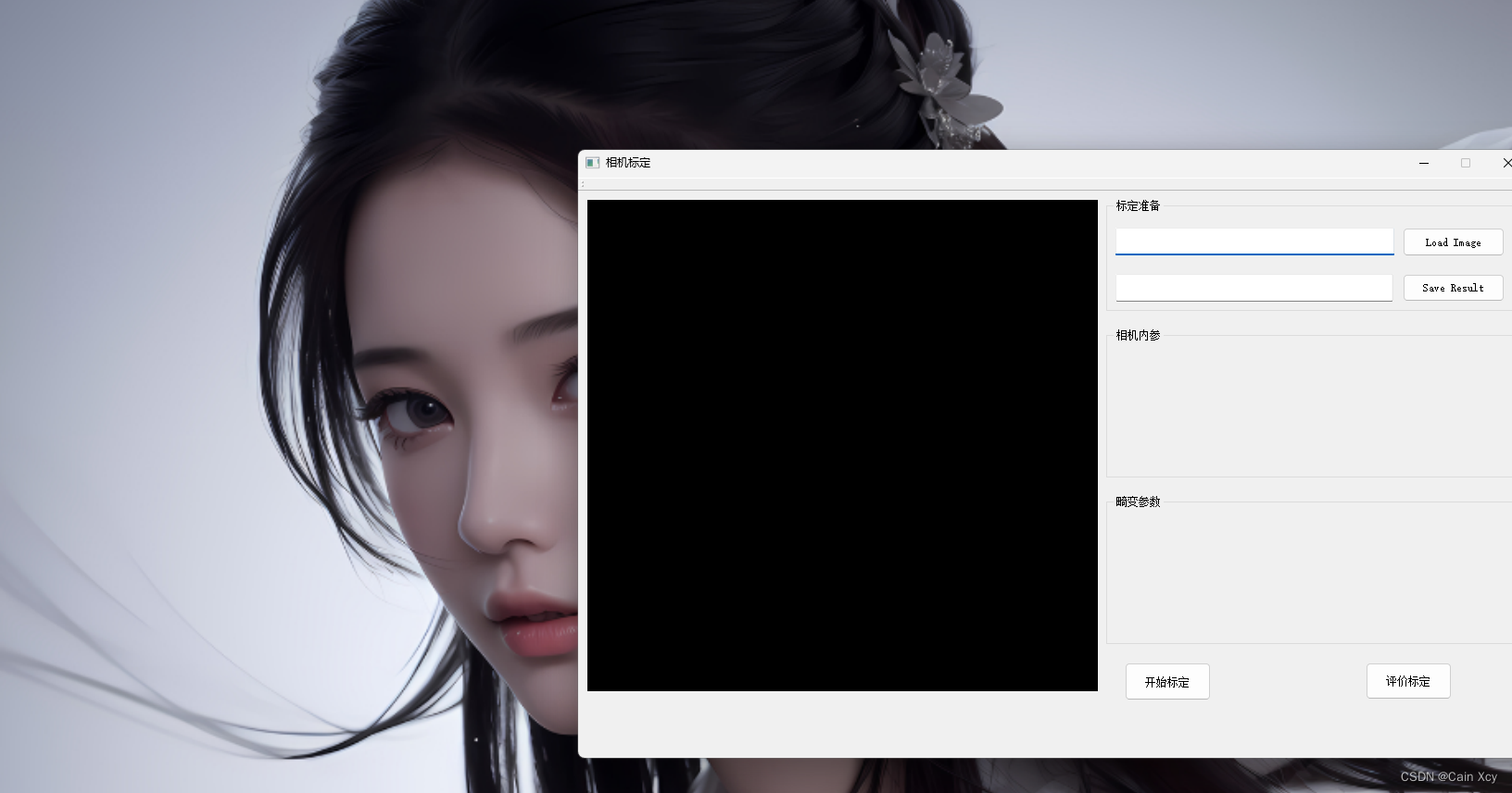
It is relatively simple to use. You input the image path and output the calibration result path, then calibrate and evaluate, and display the camera internal parameters and camera distortion. There are no camera external parameters involved here.