1. Course objectives
1. Analysis of the principle of the external power detection circuit
2. Development of the external power detection program code, and configuration of the GPIO port input mode
3. Demonstration of the external power detection function:
2. Course preparation
1. Development board
2. ST-Link
3. Standard project
Experiment results: LED7 is on when external power is connected, LED7 is off when external power is disconnected
3. Analysis of external power detection hardware
1. The source and flow diagram of external power detection hardware:
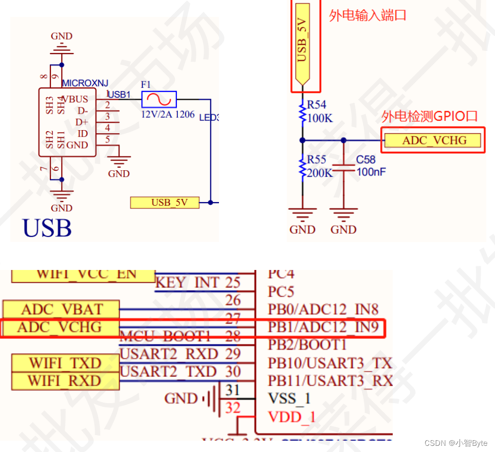
2. Principle analysis:
It can be seen from the schematic diagram that the state of the external power is detected through the PB1 port. Then analyze the state of PB1 without external power input and with external power input.
① Disconnect
PB1 from the external power supply and ground PB1 through the pull-down resistor R55 to input low level
② Connect the output port of the external power supply
to

5V power supply
. Point voltage value: VR55 =5*200 /(100+200) = 3.33V
The voltage of point A is the voltage of PB1 port: 3.33V high level