1. Laser point cloud of vehicle lidar
Through point cloud technology, lidar imaging can be clearer and more accurate, and can give full play to the advantages of high resolution. The application of point cloud can not only save the traditional modeling time, but also increase the accuracy of the model, which is one of the technical advantages of lidar.
Vehicle-mounted lidar is a mobile scanning system, which can analyze the turn-back time after the laser encounters the target object by emitting and receiving the laser beam, calculate the relative distance between the target object and the vehicle, and use the collected target object surface A large number of dense The 3D coordinates, reflectivity and other information of the point can quickly reconstruct the 3D model of the target and various map data, establish a 3D point cloud map, and draw an environmental map to achieve the purpose of environmental perception. The object information collected by lidar presents a series of scattered points with accurate angle and distance information, which is called point cloud, as shown in Figure 1.
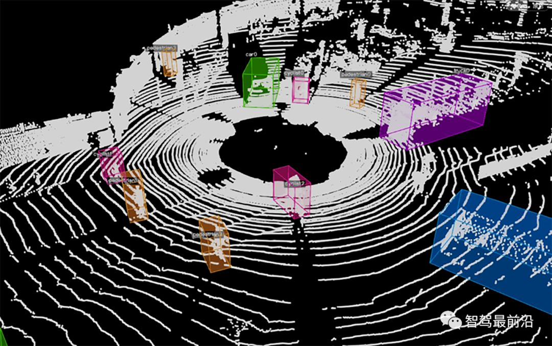
Figure 1 Target recognition of 3D point cloud
01Parameters and characteristics of laser point cloud
Laser point cloud refers to the spatial point data set scanned by 3D laser radar equipment. Each point cloud contains 3D coordinates (XYZ) and laser reflection intensity (Intensity). The intensity information will be related to the surface material and roughness of the target object, laser The incident angle, laser wavelength and the energy density of the laser radar are related. The relevant parameters and characteristics of the point cloud are as follows:
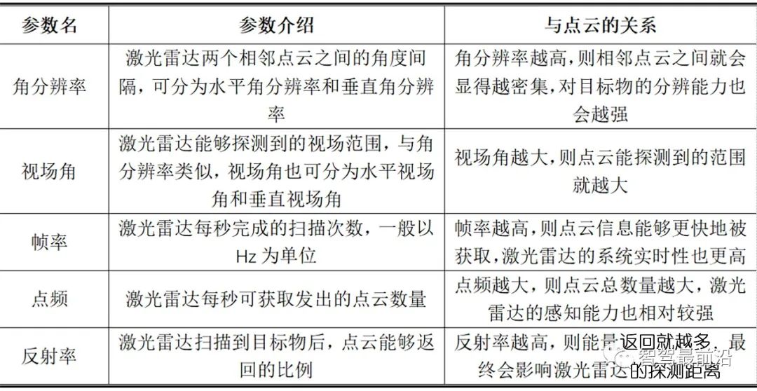
Table 1: Related parameters of lidar point cloud
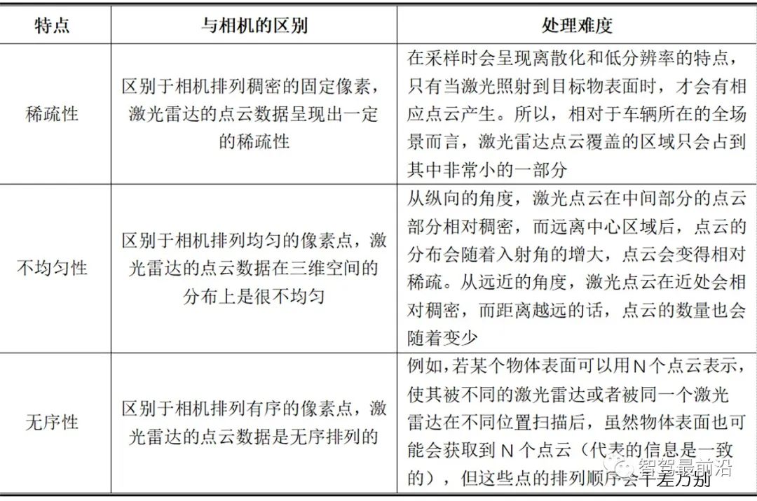
Table 2: Characteristics of point clouds
02 Receiving and analyzing the original point cloud data
1. Receiving point cloud data
The original point cloud data of lidar will be stored in a data packet (PCAP). At this time, the data in the data packet is a series of byte symbols and cannot be used directly. Taking Velodyne's 16-line lidar as an example, the original point cloud data is received mainly by sending data to the network in the form of UDP (User Datagram Protocol).
Judging from the content of the data, this type of lidar has 16 lines of laser beams in the vertical direction (-15° to +15°), and the data length of each frame is fixed at 1,248 bytes, these bytes include the first 42 The first data packet identification of bytes, 12 groups of data packets, 4 bytes of time stamp and the last two bytes of radar model parameters.
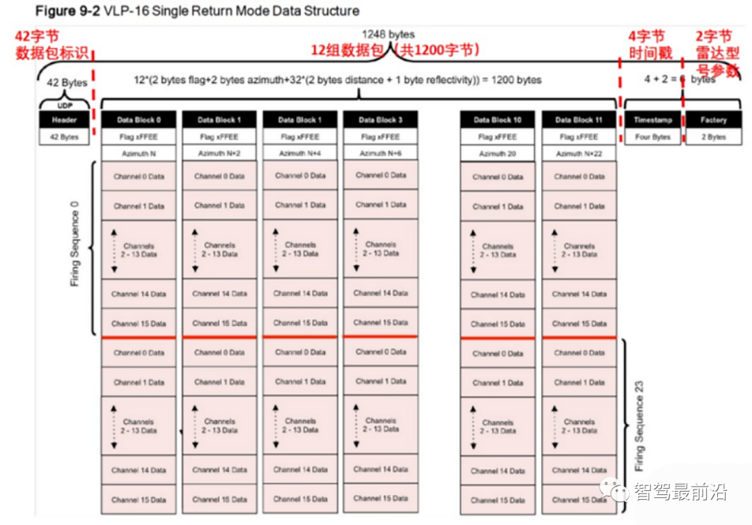
Figure 3 The point cloud data of each frame of Velodyne-16 lidar
The data in each data packet contains information about the rotation angle, distance value, and reflection intensity of the laser beam. For example, "B6 07" represents the detection range of the lidar is 3.948m, and "2A" represents the reflection intensity of the laser, but these information are expressed in two bytes, and further analysis of these data is required.
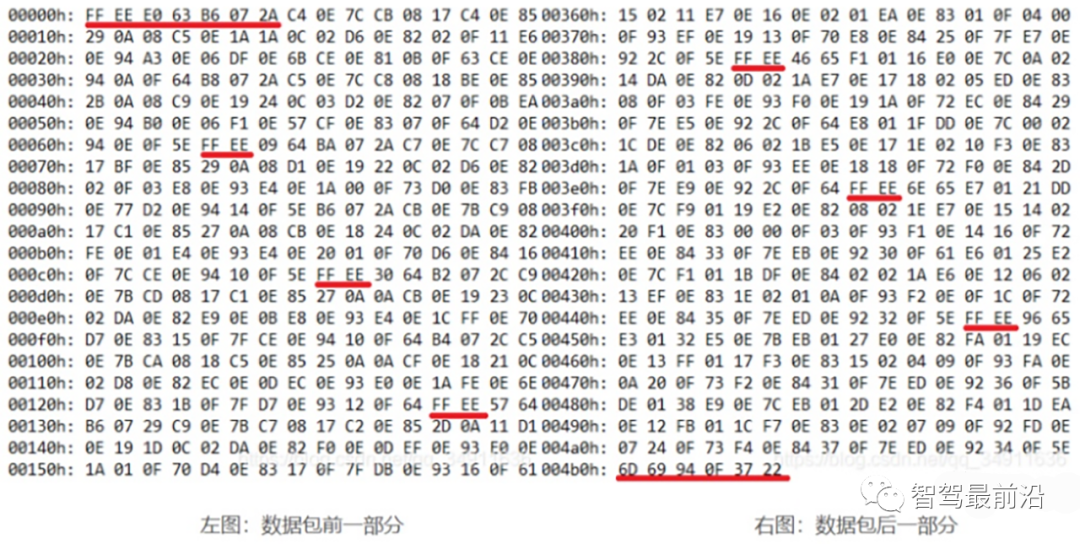
Figure 4 Part of the Velodyne-16 lidar data packet
2. Analysis of point cloud data
The raw data in the data package needs to be further converted into a data set that can be used in PCD format. The PCD file is mainly a list composed of Cartesian coordinates (x, y, z) and intensity values i, that is, each point cloud will be accompanied by a unique 3D coordinate system and energy reflection intensity.
In this coordinate system, the x-axis points to the front of the car and the y-axis points to the left side of the car. Since this coordinate system uses the right-hand rule, the z-axis of the coordinate system points up the car.
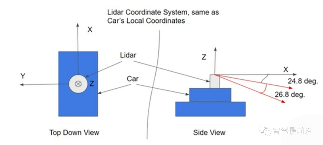
Figure 5 point cloud pcd coordinates
03 Positioning processing
After obtaining the above three-dimensional coordinates and the intensity information of each point, the vehicle will extract the road condition features and match the corresponding road sections, so as to realize its own positioning.
1. Feature extraction
The first step of using point cloud data for positioning is to first determine "where am I?" At this time, the perception algorithm device must first extract the target features of the surrounding scene, and use these features and the obtained relative distance information to establish a small map, to determine the relative initial position of the vehicle.
Point cloud feature extraction is often real-time, which leads to a very large amount of point cloud data, and the hardware performance of existing mass-produced cars is limited, so in order to reduce the calculation amount of point cloud data, point cloud data is generally extracted when features are extracted. The more obvious features are preferentially extracted, such as the outline information of the object, the line-surface angle of the target object, specifically the utility pole is the feature of the line, the road surface is the feature of the surface, and the corner of the building is the feature of the corner.
2. Map matching
After extracting the features of the surrounding objects, the perception algorithm needs to perform point cloud map matching based on these features to obtain the relative pose between each point cloud. Point cloud map matching can generally be divided into inter-frame matching and high-precision maps match.
Inter-frame matching is also called sub-image matching, which refers to matching the point clouds with the same characteristics in the previous and subsequent frames, and finally obtains a small local map; high-precision map matching refers to matching the optimized point cloud with the high-precision map. In the autopilot industry, autopilot solution providers or OEMs will apply these two different schemes, but the commonly used matching scheme is still based on inter-frame matching.
3. Pose optimization
After the point cloud data is matched, the relative pose between each point cloud (translation and rotation during the process of converting from one coordinate system to another) can be obtained, and the accuracy of the relative pose will affect The accuracy of building the map, so it is necessary to optimize the relative pose of the point cloud.
The inaccuracy of the relative pose is mainly due to some uncontrollable factors, such as the point cloud being blocked by objects or the limitation of the lidar field of view. The pose optimization of the point cloud is achieved through the rigid body change (rotation or translation) of a certain point cloud coordinate system. Get the best relative pose.
2. Classification and development of automotive lidar
01 Mechanical lidar
The mechanical laser radar drives the transceiver array to rotate as a whole through the motor, and can scan the 360° field of view in the spatial level. Its transmitting system and receiving system are macroscopically rotated, and the transmitting components are vertically arranged into a linear array of laser light sources, and laser beams in different directions are generated on the vertical plane through the lens. Driven by the stepping motor, the laser beam in the vertical plane is continuously rotated from the "line" to the "plane", and multiple excitations are formed by rotating the scanning light "plane", so as to realize the three-dimensional scanning of the detection area and form a point cloud.
In 2005, Velodyne first proposed a three-dimensional mechanical rotary scanning technology for laser radar (application number: US11777802), which successfully realized the 360-degree scanning of laser radar, and took the lead in making up for the blank of three-dimensional vehicle laser radar scanning technology. , the mechanical lidar is available. At present, the company has launched the Alpha PUCK lidar that uses 128 wires and increases the detection distance to 300 meters; in China, Hesai Technology has also released the Pandar series of mechanical lidars, of which Panndar128 uses 128 wires, and the ranging range reaches 200 meters. The technology of mechanical lidar is relatively mature.
As the most classic and mature technical solution of lidar, mechanical lidar is often used in the test and iteration of self-driving taxis, but the traditional discrete design of mechanical radar is mainly achieved by adding transceiver modules to achieve high wiring harness. , although higher-precision detection can be achieved, the entire set of components is bulky and has limited space for cost reduction.
02Hybrid solid-state lidar MEMS
Hybrid solid-state lidar MEMS (Micro Electromechanical System) is a semiconductor "micro-movement" device instead of a mechanical scanner to realize laser scanning at the radar transmitter on a microscopic scale. MEMS lidar combines MEMS (a high-tech device with an internal structure in the micron or even nanometer) and a vibrating mirror (a silicon-based semiconductor component, which belongs to a solid-state electronic component), and drives the vibrating mirror to move through MEMS , the laser is emitted in all directions through the galvanometer, so it is called a hybrid solid-state lidar.
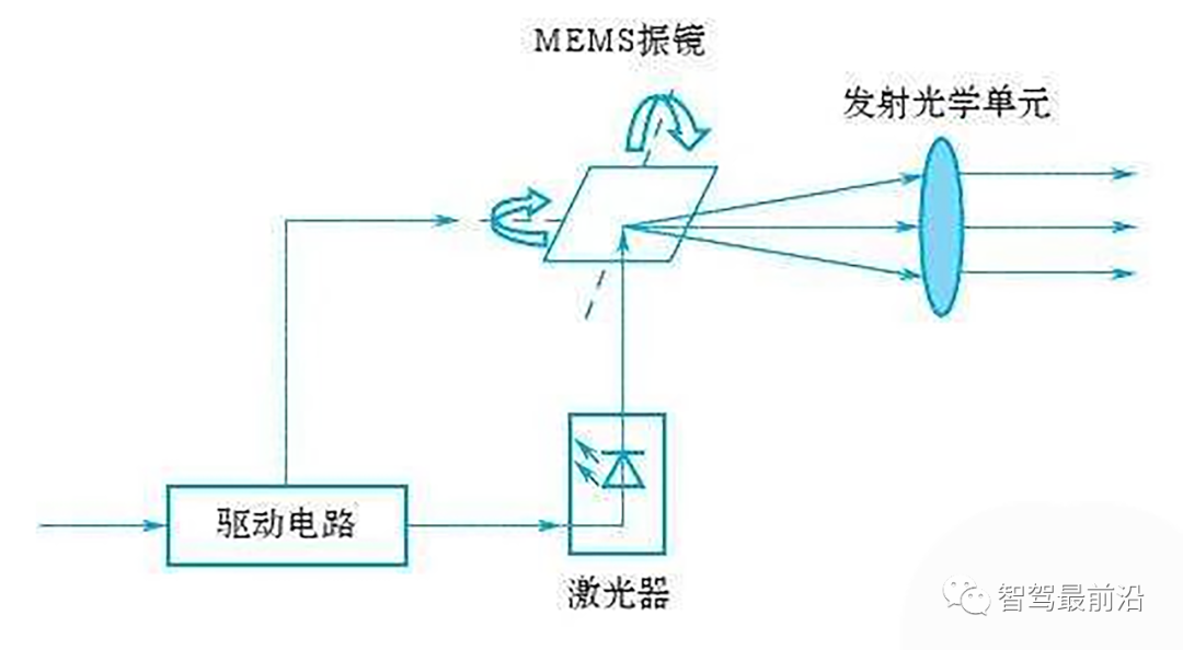
Figure 7 Hybrid solid-state laser radar MEMS launch system structure
MEMS lidar integrates all mechanical components into a single chip and produces them using semiconductor technology to achieve miniaturization and electronic design of mechanical structures. As shown in Figure 8, when the MEMS emits laser light, the driving circuit acts on the laser and the MEMS vibrating mirror at the same time, so that the laser generates laser pulses and the MEMS vibrating mirror rotates. At this time, the emitted pulse is scanned by the laser under the continuous rotation and reflection of the vibrating mirror, and finally collimated by the optical unit before being emitted.
As an upgrade of mechanical rotation scanning lidar, MEMS lidar has been widely used. At present, the field of mass-produced vehicles is mainly equipped with hybrid solid-state lidar. Since 2020, 21 models around the world have announced that they will be equipped with lidar, and Chinese companies have launched 14 of them. These car companies mainly choose hybrid solid-state lidar.
The first MEMS hybrid solid-state lidar was the Innoviz One released by the Israeli company Innoviz in 2017; Sagitar followed closely and launched the M1 similar to the Innoviz One in the same year. Another promising hybrid solid-state route is the single-axis rotating mirror, which is the solution used by Scala. Hesai Technology launched the 128-line laser radar AT128 in the fourth quarter of 2021, and has now become the designated supplier of Lixiang, Jidu, Geely's Lotus, Gaohe and other brands.
Hybrid solid-state lidar can be divided into one-dimensional scanning and two-dimensional scanning. What they have in common is that they change the direction of the laser through internal mechanical movement; the difference is that one-dimensional scanning only changes the horizontal direction, and two-dimensional scanning changes both horizontal and vertical directions at the same time. direction. The scheme of one-dimensional scanning is to use the reflector in the horizontal direction to change the light direction to obtain the coverage of the field of view; two-dimensional scanning has two schemes, one is that the vibrating mirror moves periodically at high speed in the horizontal and vertical axes through the cantilever beam, so that Scanning is achieved by changing the laser reflection direction, and the other is scanning by a polygonal prism that rotates continuously on the horizontal axis and a mirror that swings on the vertical axis. These three options are described in detail below.
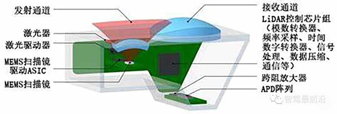
Figure 8 The internal structure of hybrid solid-state lidar MEMS
1. Two-dimensional scanning
2D scanning can be further subdivided into MEMS and 2D rotating mirrors.
(1) The core of the MEMS solution is a centimeter-scale vibrating mirror that moves periodically at high speed in the horizontal and vertical axes through a cantilever beam, thereby changing the laser reflection direction to realize scanning. Compared with the traditional mechanical laser radar, the MEMS solution simplifies the scanning structure, and the scanning path can be changed by controlling the deflection angle of the micro-vibration mirror. Only a few lasers are needed to achieve the coverage area and point cloud of the mechanical multi-beam laser radar. Same effect as density.
However, the technical difficulty of this solution is that the rotation angle of the cantilever beam is limited, so that the field of view covered by a single galvanometer is very small, and multiple splicing is often required to achieve a large field of view coverage, which may cause unevenness of the point cloud image at the superimposed edge Distortion and overlap, which increases the difficulty of subsequent algorithm processing.
(2) The two-dimensional rotating mirror scheme consists of a polygonal prism that rotates continuously on the horizontal axis and a mirror that can swing on the vertical axis. For example, the following is a schematic diagram of an existing two-dimensional rotating mirror scanning on the market. The continuously rotating polygonal prism can enable the light source to scan horizontally, while the vertical axis swing mirror can change the vertical scanning direction of the light source.
According to this design scheme, only one beam of light source is needed to complete the scanning task that can only be completed by several light sources of mechanical radar, but because there is only one beam of laser, the scanning frequency is very high to ensure high-definition scanning of the three-dimensional world, and at the same time Power requirements are also greater, presenting reliability challenges for scanning devices.
2. One-dimensional scanning
Compared with the two-dimensional scanning structure, the one-dimensional scanning uses a mirror that only rotates at a low speed in the horizontal direction to change the direction of the light to obtain the coverage of the field of view, which has higher stability and reliability. In 2017, Valeo launched the first laser radar in the industry that passed the verification of vehicle regulations, which adopted this technical solution, but the limitation of this solution is that the number of scanning lines is small, and it is difficult to achieve high resolution .
03 Solid-state lidar
Both mechanical and semi-solid-state transceiver modules are paired with a scanning module for mechanical movement. They cannot be regarded as pure solid-state. In the final analysis, the scanning module is just a mechanical component and a "form". The "essence" that really determines the performance of the lidar is its transceiver module. Only those without any moving parts inside are pure solid-state lidars, which have the simplest structure and the highest integration. Theoretically speaking, solid-state lidar is a radar with no moving parts at all. Optical phased array (Optical Phased Array) and Flash are typical technical routes, and are also considered pure solid-state lidar solutions.
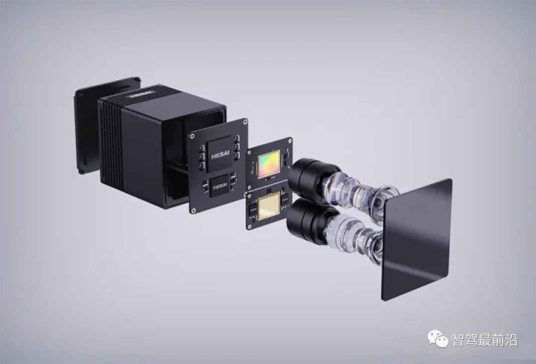
Figure 11: Hesai Technology FT120 solid-state lidar
1. OPA solid-state lidar
OPA (phased array) lidar is a type of lidar that uses optical phase control array technology to realize laser scanning. The OPA transmitter is composed of multiple independently controllable transmitting and receiving units. Changing the voltage applied to it can change the characteristics of the light waves emitted by each unit, and then achieve mutual enhancement in a certain direction by adjusting the phase relationship between the emitted light waves. Interference, resulting in a directional high-intensity beam. Under the control of a well-designed program, each phase control unit of OPA enables the direction of one or more high-intensity beams to realize random spatial scanning.
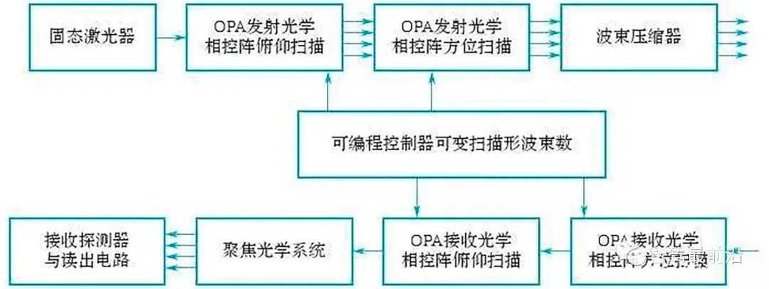
Figure 12 OPA lidar block diagram
2. Flash solid-state lidar
Flash (flood array) lidar is a lidar that calculates environmental distance by recording photon flight time, and belongs to non-scanning lidar. During operation, the imaging system (a high-density array of laser sources) emits a large area of laser light to cover the detection area. Due to the different distances from the surface of the object to the return point, the flight time of the pixels reflected back on the image after the light source reaches the surface of the object is also different. The high-sensitivity receiver inside the radar calculates the distance corresponding to each pixel to complete the information on the surrounding environment. collection and drawing.
Flash lidar is one of the mainstream technical products in all solid-state lidar at present. Its main advantages include fast imaging speed, low cost, high integration, non-discrete acquisition, and the ability to improve the spatial understanding of the perception system for the environment. However, due to the limitation of chip technology, the current application range of Flash lidar is relatively small. In addition, multiple emitters emit pulsed lasers at the same time, which also limits the power of its modules.
The advantage of solid-state lidar is that it can minimize the wear and tear caused by movable mechanical structures such as motors and bearings, and at the same time eliminate the possible failure of optoelectronic devices due to mechanical rotation, making the internal structure layout of solid-state lidar more reasonable and the overall heat dissipation And stability is a qualitative leap compared to mechanical lidar.
Solid-state lidar cancels the complex and high-frequency rotating mechanical structure, which can reduce material and mass production costs, improve product reliability, production efficiency and consistency, and will develop in the field of car-level mass production in the future.
The shortcomings of solid-state lidar at this stage lie in low power density and short detection distance, and it cannot be used in mass production as the main lidar. However, the short-range blindness compensation of solid-state lidar can be combined with the long-range perception of semi-solid-state lidar , to create a complete automotive-grade lidar solution.
Table 3: Comparison of three lidars

The installation position of the vehicle lidar
As shown in Figure 14, the installation positions of lidar are divided into two categories: one is installed around the ICV, and the other is installed on the roof of the ICV. For the laser radar installed around the intelligent network car, the laser beam is generally less than 8, and the common ones are single-line laser radar and 4-line laser radar. For the lidar installed on the roof of an intelligent networked car, its laser wiring harness is generally not less than 16, and the common ones are 16, 32, and 64-line lidar. No matter where it is installed, the following requirements must be met.
Figure 14 LiDAR installation location
1. Firstly, according to the anti-vibration and impact capability of the radar, determine whether a vibration-damping bracket is needed.
2. If you do not need a vibration damping bracket, you can use the mounting lugs or other fixing screw holes on the radar.
3. The obstacle avoidance radar requires a horizontal tilt of about 5° upwards to solve the detection of highly reflective objects.
4. The measurement radar requires the installation plane to be parallel to the ground as much as possible, which is used to improve the general positioning accuracy. This is because if there is an inclination angle, there will be large errors in the contours detected by the radar at different positions, which will eventually affect the positioning accuracy.
5. The installation position of the laser head should not exceed 200mm from the roof of the car, and the installation position at a height of about 170mm is the best (it can be used for safe obstacle avoidance and measurement). According to the body structure, the radar can be installed forward or upside down.
6. On the radar layout, you can choose the middle position of the front of the car or the four diagonal points of the car. If two radars are arranged at opposite corners of the car, the 360° of the car body can be detected by the lidar, so that there is no dead angle for obstacle avoidance.
7. For different car bodies, there will be errors in the installation x, y direction and rotation attitude of the radar, which will eventually lead to the same positioning point in theory, but different positions and attitudes of the car body. The system needs to set the compensation values of these three errors to ensure their consistency.
References
1. Analysis of the principle of lidar that can be understood at a glance - Zhihu https://zhuanlan.zhihu.com/p/443488190
2. An article to understand the working principle of Lidar (Lidar), and radar (Radar), point cloud data related technologies and application fields - Know about
3. https://zhuanlan.zhihu.com/p/449269751
4. Hesai Technology Prospectus - Hesai
Reprinted from Zhizao Talk, the opinions in the article are for sharing and exchange only, and do not represent the position of this official account. If copyright issues are involved, please let us know, and we will deal with them in a timely manner.