I.MX6ULL Network Peripherals Device Tree
I.MX6ULL has two 10/100M network MAC peripherals, so the I.MX6ULL network driver is mainly the driver of these two network MAC peripherals. The drivers of these two peripherals are the same. Let’s analyze one of them. First, it must be the device tree. NXP’s I.MX series SOC network binding document is Documentation/devicetree/bindings/net/fsl-fec.txt , this binding document describes the requirements of the I.MX series SOC network device tree node.
①. Necessary attributes
compatible: This is definitely necessary, usually "fsl,-fec", for example, the compatible attribute of I.MX6ULL is "fsl,imx6ul-fec", and "fsl,imx6q-fec".
reg: SOC network peripheral register address range.
interrupts: network interruption.
phy-mode: The PHY interface mode used by the network, whether it is MII or RMII.
②, optional attributes
phy-reset-gpios: The reset pin of the PHY chip.
phy-reset-duration: PHY reset pin reset duration, in milliseconds. This attribute will only be valid if the phy-reset-gpios attribute is set. If this attribute is not set, the reset duration of the PHY chip reset pin is 1 millisecond by default, and the value cannot be greater than 1000 milliseconds. If it is greater than 1000 milliseconds, it will be forced is 1 millisecond.
phy-supply: Power regulation for the PHY chip.
phy-handle: The PHY chip handle connected to this network device.
fsl,num-tx-queues: This attribute specifies the number of send queues, if not specified, the default is 1.
fsl,num-rx-queues: This attribute specifies the number of receive queues, if not specified, the default is 2.
fsl,wakeup_irq: This attribute sets the wakeup interrupt index.
stop-mode: If this attribute exists, it indicates that the SOC needs to set the GPR bit to request stop mode.
③, Optional child nodes
mdio: You can set a child node named "mdio". This child node is used to specify the MDIO bus used by the network peripherals. It is mainly used as a container for the PHY node, that is, specify the PHY-related attribute information under the mdio child node. For information, refer to the PHY binding document Documentation/devicetree/bindings/net/phy.txt.
The relevant attributes of the PHY node are as follows:
interrupts: interrupt attribute, may not be required.
interrupt-parent: Interrupt controller handle, not required.
reg: PHY chip address, must!
compatible: Compatibility list, generally "ethernet-phy-ieee802.3-c22" or "ethernet-phy-ieee802.3-c45", respectively corresponding to 22 clusters and 45 clusters of IEEE802.3, the default is 22 clusters. It can also be set to other values. If the ID of the PHY is unknown, the compatible attribute can be set to "ethernet-phy-idAAAA.BBBB". The meanings of AAAA and BBBB are as follows:
AAAA: The 16-bit ID register 1 value of the PHY, that is, bit3~18 of the OUI, in hexadecimal format.
BBBB: 16-bit ID register 2 value of PHY, that is, bit19~24 of OUI, in hexadecimal format.
max-speed: The highest speed supported by the PHY, such as 10, 100 or 1000.
Open imx6ull.dtsi and find two network peripheral nodes of I.MX6ULL, as shown in the figure:
 fec1: ethernet@02188000 {
     compatible = "fsl,imx6ul-fec", "fsl,imx6q-fec";
     reg = <0x02188000 0x4000>;
     interrupts = <GIC_SPI 118 IRQ_TYPE_LEVEL_HIGH>,
                           <GIC_SPI 119 IRQ_TYPE_LEVEL_HIGH>;
     clocks = <&clks IMX6UL_CLK_ENET>,
                  <&clks IMX6UL_CLK_ENET_AHB>,
                  <&clks IMX6UL_CLK_ENET_PTP>,
                  <&clks IMX6UL_CLK_ENET_REF>,
                  <&clks IMX6UL_CLK_ENET_REF>;
     clock-names = "ipg", "ahb", "ptp",
                   "enet_clk_ref", "enet_out";
     stop-mode = <&gpr 0x10 3>;
     fsl,num-tx-queues=<1>;
     fsl,num-rx-queues=<1>;
     fsl,magic-packet;
     fsl,wakeup_irq = <0>;
     status = "disabled";
};

 fec2: ethernet@020b4000 {
    compatible = "fsl,imx6ul-fec", "fsl,imx6q-fec";
    reg = <0x020b4000 0x4000>;
    interrupts = <GIC_SPI 120 IRQ_TYPE_LEVEL_HIGH>,
            <GIC_SPI 121 IRQ_TYPE_LEVEL_HIGH>;
    clocks = <&clks IMX6UL_CLK_ENET>,
       <&clks IMX6UL_CLK_ENET_AHB>,
       <&clks IMX6UL_CLK_ENET_PTP>,
       <&clks IMX6UL_CLK_ENET2_REF_125M>,
       <&clks IMX6UL_CLK_ENET2_REF_125M>;
    clock-names = "ipg", "ahb", "ptp",
       "enet_clk_ref", "enet_out";
    stop-mode = <&gpr 0x10 4>;
    fsl,num-tx-queues=<1>;
    fsl,num-rx-queues=<1>;
    fsl,magic-packet;
    fsl,wakeup_irq = <0>;
    status = "disabled";
};
fec1 and fec2 respectively correspond to ENET1 and ENET2 of I.MX6ULL. As for the specific properties of the nodes, we won't analyze them. It has already been mentioned in detail when explaining the binding document above. The sample code 69.4.1.1 is officially written by NXP, we don't need to modify it, but the sample code 69.4.1.1 cannot work, and some attributes need to be added or modified according to the actual situation. Open imx6ull-alientek-emmc.dts and find the following content:
&fec1 {
pinctrl-names = "default";
pinctrl-0 = <&pinctrl_enet1
&pinctrl_enet1_reset>;
phy-mode = "rmii";
phy-handle = <ðphy0>;
phy-reset-gpios = <&gpio5 7 GPIO_ACTIVE_LOW>;
phy-reset-duration = <200>;
status = "okay";
};
&fec2 {
pinctrl-names = "default";
pinctrl-0 = <&pinctrl_enet2
&pinctrl_enet2_reset>;
phy-mode = "rmii";
phy-handle = <ðphy1>;
phy-reset-gpios = <&gpio5 8 GPIO_ACTIVE_LOW>;
phy-reset-duration = <200>;
status = "okay";
mdio {
#address-cells = <1>;
#size-cells = <0>;
ethphy0: ethernet-phy@0 {
compatible = "ethernet-phy-ieee802.3-c22";
reg = <0>;
};
ethphy1: ethernet-phy@1 {
compatible = "ethernet-phy-ieee802.3-c22";
reg = <1>;
};
};
Lines 1 to 10: the node attributes of the ENET1 network port. Lines 3 and 4 set the pinctrl node information used by ENET1. Line 5 sets the PHY chip interface corresponding to the network to RMII. This should be set according to the actual hardware . Line 6 sets the handle of the PHY chip to ethphy0, and the MDIO node will set the PHY information. Other attribute information is easy to understand, and it has basically been mentioned above when explaining the binding document.
Lines 12 to 36: The node attributes of the ENET2 network port are basically the same as those of the ENET1 network port. The difference is that there are more mdio child nodes in lines 22 to 35. As mentioned earlier when explaining the binding document, the mido child node is used to describe MIDO bus, this sub-node will contain PHY node information. There are two PHY sub-nodes here: ethphy0 and ethphy1, corresponding to the PHY chips of ENET1 and ENET2 respectively. For example, "ethphy0: ethernet-phy@0" in line 26 is the PHY node name of ENET1, the 0 behind "@" is the chip address of this PHY chip, and the reg attribute also describes the PHY chip address, which is similar to the IIC device node very similar. There is not much else in other places, and the binding documentation has explained it very clearly.
Finally, there is a description of the network-related pins in the device tree. Open imx6ull-alientek-emmc.dts and find the following content:
1 pinctrl_enet1: enet1grp {
2     fsl,pins = <
3     MX6UL_PAD_ENET1_RX_EN__ENET1_RX_EN 0x1b0b0
4     MX6UL_PAD_ENET1_RX_ER__ENET1_RX_ER 0x1b0b0
5     MX6UL_PAD_ENET1_RX_DATA0__ENET1_RDATA00 0x1b0b0
6     MX6UL_PAD_ENET1_RX_DATA1__ENET1_RDATA01 0x1b0b0
7     MX6UL_PAD_ENET1_TX_EN__ENET1_TX_EN 0x1b0b0
8     MX6UL_PAD_ENET1_TX_DATA0__ENET1_TDATA00 0x1b0b0
9     MX6UL_PAD_ENET1_TX_DATA1__ENET1_TDATA01 0x1b0b0
10    MX6UL_PAD_ENET1_TX_CLK__ENET1_REF_CLK1 0x4001b009
11 >;
12 };
13
14 pinctrl_enet2: enet2grp {
15     fsl,pins = <
16     MX6UL_PAD_GPIO1_IO07__ENET2_MDC 0x1b0b0
17     MX6UL_PAD_GPIO1_IO06__ENET2_MDIO 0x1b0b0
18     MX6UL_PAD_ENET2_RX_EN__ENET2_RX_EN 0x1b0b0
19     MX6UL_PAD_ENET2_RX_ER__ENET2_RX_ER 0x1b0b0
20     MX6UL_PAD_ENET2_RX_DATA0__ENET2_RDATA00 0x1b0b0
21     MX6UL_PAD_ENET2_RX_DATA1__ENET2_RDATA01 0x1b0b0
22     MX6UL_PAD_ENET2_TX_EN__ENET2_TX_EN 0x1b0b0
23     MX6UL_PAD_ENET2_TX_DATA0__ENET2_TDATA00 0x1b0b0
24     MX6UL_PAD_ENET2_TX_DATA1__ENET2_TDATA01 0x1b0b0
25     MX6UL_PAD_ENET2_TX_CLK__ENET2_REF_CLK2 0x4001b009
26     >;
27 };
28
29 /*enet1 reset zuozhongkai*/
30 pinctrl_enet1_reset: enet1resetgrp {
31     fsl,pins = <
32 /* used for enet1 reset */
33     MX6ULL_PAD_SNVS_TAMPER7__GPIO5_IO07 0x10B0
34     >;
35 };
36
37 /*enet2 reset zuozhongkai*/
38 pinctrl_enet2_reset: enet2resetgrp {
39     fsl,pins = <
40 /* used for enet2 reset */
41     MX6ULL_PAD_SNVS_TAMPER8__GPIO5_IO08 0x10B0
42     >;
43 };
pinctrl_enet1 and pinctrl_enet1_reset are the pinctrl information of all IO pins of ENET1. The reason why they are divided into two parts is that the reset pin of ENET1 is GPIO5_IO07, and the corresponding pin of GPIO5_IO07 is SNVS_TAMPER7, which should be placed under the iomuxc_snvs node, so it is divided into two parts. part. Pay attention to lines 16 and 17. These two lines set GPIO1_IO07 and GPIO1_IO06 as MDC and MDIO of ENET2. You may wonder why not set them as MDC and MDIO of ENET1? After the author's actual measurement, when two network ports are opened, setting GPIO1_IO07 and GPIO1_IO06 as MDC and MDIO of ENET1 will cause the network to work abnormally. As mentioned earlier, one MDIO interface can manage 32 PHYs, so after setting the MDC and MDIO of ENET2, it can also manage the PHY chip on ENET1.
I.MX6ULL network driver source code analysis
1. Brief analysis of fec_probe function
For I.MX6ULL, the network driver is mainly divided into two parts: I.MX6ULL network peripheral driver and PHY chip driver. The network peripheral driver is written by NXP, and the PHY chip has a general driver file. Some PHY chip manufacturers will also target their own Write the corresponding PHY driver for the chip. Generally speaking, we do not need to write any drivers for the solution of SOC built-in network MAC + external PHY chip, and can basically be used directly. But in order to learn, we still need to briefly analyze the specific network driver writing process.
Let’s take a look at the network controller driver of I.MX6ULL first. It can be seen from the sample code 69.4.1.1 that the compatible attribute has two values “fsl, imx6ul-fec” and “fsl, imx6q-fec”, through the linux Search for these two strings in the kernel source code to find the corresponding driver file, the driver file is drivers/net/ethernet/freescale/fec_main.c, open fec_main.c, and find the following content:
1 static const struct of_device_id fec_dt_ids[] = {
2     { .compatible = "fsl,imx25-fec", .data =
            &fec_devtype[IMX25_FEC], },
3     { .compatible = "fsl,imx27-fec", .data =
            &fec_devtype[IMX27_FEC], },
4     { .compatible = "fsl,imx28-fec", .data =
            &fec_devtype[IMX28_FEC], },
5     { .compatible = "fsl,imx6q-fec", .data =
            &fec_devtype[IMX6Q_FEC], },
6     { .compatible = "fsl,mvf600-fec", .data =
            &fec_devtype[MVF600_FEC], },
7     { .compatible = "fsl,imx6sx-fec", .data =
            &fec_devtype[IMX6SX_FEC], },
8     { .compatible = "fsl,imx6ul-fec", .data =
            &fec_devtype[IMX6UL_FEC], },
9     { /* sentinel */ }
10 };
11
12 static struct platform_driver fec_driver = {
13         .driver = {
14             .name = DRIVER_NAME,
15             .pm = &fec_pm_ops,
16             .of_match_table = fec_dt_ids,
17         },
18         .id_table = fec_devtype,
19         .probe = fec_probe,
20         .remove = fec_drv_remove,
21 };
Line 8, the matching table contains "fsl, imx6ul-fec", so the device tree and the driver are matched. When the match is successful, the fec_probe function in line 19 will be executed. Let's briefly analyze the fec_probe function. The content of the function is as follows:
1 static int fec_probe(struct platform_device *pdev)
2 {
3       struct fec_enet_private *fep;
4       struct fec_platform_data *pdata;
5       struct net_device *ndev;
6       int i, irq, ret = 0;
7       struct resource *r;
8       const struct of_device_id *of_id;
9       static int dev_id;
10      struct device_node *np = pdev->dev.of_node, *phy_node;
11      int num_tx_qs;
12      int num_rx_qs;
13
14     fec_enet_get_queue_num(pdev, &num_tx_qs, &num_rx_qs);
15
16     /* Init network device */
17     ndev = alloc_etherdev_mqs(sizeof(struct fec_enet_private),
18              num_tx_qs, num_rx_qs);
19     if (!ndev)
20        return -ENOMEM;
21
22     SET_NETDEV_DEV(ndev, &pdev->dev);
23
24    /* setup board info structure */
25    fep = netdev_priv(ndev);
26
27    of_id = of_match_device(fec_dt_ids, &pdev->dev);
28    if (of_id)
29      pdev->id_entry = of_id->data;
30      fep->quirks = pdev->id_entry->driver_data;
31
32   fep->netdev = ndev;
33   fep->num_rx_queues = num_rx_qs;
34   fep->num_tx_queues = num_tx_qs;
35
36 #if !defined(CONFIG_M5272)
37     /* default enable pause frame auto negotiation */
38     if (fep->quirks & FEC_QUIRK_HAS_GBIT)
39          fep->pause_flag |= FEC_PAUSE_FLAG_AUTONEG;
40 #endif
41
42     /* Select default pin state */
43     pinctrl_pm_select_default_state(&pdev->dev);
44
45     r = platform_get_resource(pdev, IORESOURCE_MEM, 0);
46     fep->hwp = devm_ioremap_resource(&pdev->dev, r);
47     if (IS_ERR(fep->hwp)) {
48          ret = PTR_ERR(fep->hwp);
49          goto failed_ioremap;
50      }
51
52      fep->pdev = pdev;
53      fep->dev_id = dev_id++;
54
55      platform_set_drvdata(pdev, ndev);
56
57      fec_enet_of_parse_stop_mode(pdev);
58
59      if (of_get_property(np, "fsl,magic-packet", NULL))
60         fep->wol_flag |= FEC_WOL_HAS_MAGIC_PACKET;
61
62      phy_node = of_parse_phandle(np, "phy-handle", 0);
63      if (!phy_node && of_phy_is_fixed_link(np)) {
64         ret = of_phy_register_fixed_link(np);
65        if (ret < 0) {
66              dev_err(&pdev->dev,
67                       "broken fixed-link specification\n");
68                 goto failed_phy;
69         }
70         phy_node = of_node_get(np);
71      }
72     fep->phy_node = phy_node;
73
74      ret = of_get_phy_mode(pdev->dev.of_node);
75      if (ret < 0) {
76        pdata = dev_get_platdata(&pdev->dev);
77        if (pdata)
78            fep->phy_interface = pdata->phy;
79        else
80            fep->phy_interface = PHY_INTERFACE_MODE_MII;
81      } else {
82            fep->phy_interface = ret;
83      }
84
85      fep->clk_ipg = devm_clk_get(&pdev->dev, "ipg");
86      if (IS_ERR(fep->clk_ipg)) {
87          ret = PTR_ERR(fep->clk_ipg);
88          goto failed_clk;
89      }
90
91      fep->clk_ahb = devm_clk_get(&pdev->dev, "ahb");
92      if (IS_ERR(fep->clk_ahb)) {
93           ret = PTR_ERR(fep->clk_ahb);
94           goto failed_clk;
95      }
96
97      fep->itr_clk_rate = clk_get_rate(fep->clk_ahb);
98
99      /* enet_out is optional, depends on board */
100       fep->clk_enet_out = devm_clk_get(&pdev->dev, "enet_out");
101       if (IS_ERR(fep->clk_enet_out))
102          fep->clk_enet_out = NULL;
103
104     fep->ptp_clk_on = false;
105     mutex_init(&fep->ptp_clk_mutex);
106
107     /* clk_ref is optional, depends on board */
108     fep->clk_ref = devm_clk_get(&pdev->dev, "enet_clk_ref");
109     if (IS_ERR(fep->clk_ref))
110        fep->clk_ref = NULL;
111
112     fep->bufdesc_ex = fep->quirks & FEC_QUIRK_HAS_BUFDESC_EX;
113     fep->clk_ptp = devm_clk_get(&pdev->dev, "ptp");
114     if (IS_ERR(fep->clk_ptp)) {
115        fep->clk_ptp = NULL;
116        fep->bufdesc_ex = false;
117     }
118
119     pm_runtime_enable(&pdev->dev);
120     ret = fec_enet_clk_enable(ndev, true);
121     if (ret)
122       goto failed_clk;
123
124    fep->reg_phy = devm_regulator_get(&pdev->dev, "phy");
125    if (!IS_ERR(fep->reg_phy)) {
126       ret = regulator_enable(fep->reg_phy);
127    if (ret) {
128        dev_err(&pdev->dev,
129                 "Failed to enable phy regulator: %d\n", ret);
130       goto failed_regulator;
131     }
132 } else {
133       fep->reg_phy = NULL;
134 }
135
136    fec_reset_phy(pdev);
137
138    if (fep->bufdesc_ex)
139        fec_ptp_init(pdev);
140
141     ret = fec_enet_init(ndev);
142     if (ret)
143     goto failed_init;
144
145     for (i = 0; i < FEC_IRQ_NUM; i++) {
146       irq = platform_get_irq(pdev, i);
147      if (irq < 0) {
148          if (i)
149             break;
150           ret = irq;
151           goto failed_irq;
152      }
153      ret = devm_request_irq(&pdev->dev, irq, fec_enet_interrupt,
154                                                0, pdev->name, ndev);
155      if (ret)
156           goto failed_irq;
157
158       fep->irq[i] = irq;
159     }
160
161     ret = of_property_read_u32(np, "fsl,wakeup_irq", &irq);
162     if (!ret && irq < FEC_IRQ_NUM)
163           fep->wake_irq = fep->irq[irq];
164     else
165            fep->wake_irq = fep->irq[0];
166
167     init_completion(&fep->mdio_done);
168     ret = fec_enet_mii_init(pdev);
169     if (ret)
170        goto failed_mii_init;
171
172     /* Carrier starts down, phylib will bring it up */
173     netif_carrier_off(ndev);
174     fec_enet_clk_enable(ndev, false);
175     pinctrl_pm_select_sleep_state(&pdev->dev);
176
177     ret = register_netdev(ndev);
178     if (ret)
179       goto failed_register;
180
181    device_init_wakeup(&ndev->dev, fep->wol_flag &
182    FEC_WOL_HAS_MAGIC_PACKET);
183
184    if (fep->bufdesc_ex && fep->ptp_clock)
185     netdev_info(ndev, "registered PHC device %d\n", fep->dev_id);
186
187    fep->rx_copybreak = COPYBREAK_DEFAULT;
188    INIT_WORK(&fep->tx_timeout_work, fec_enet_timeout_work);
189    return 0;
......
206    return ret;
207 }
Line 14, use the fec_enet_get_queue_num function to get the two attribute values of "fsl, num-tx-queues" and "fsl, num-rx-queues" in the device tree, that is, the size of the sending queue and receiving queue, the device tree Both properties are set to 1 in .
Line 17, use the alloc_etherdev_mqs function to apply for net_device.
Line 25, get the first address of private data memory in net_device, the private data in net_device is used to store I.MX6ULL network device structure, this structure is fec_enet_private.
Line 30, all subsequent lines of code beginning with "fep->" are to initialize each member variable of the network device structure. The structure type is fec_enet_private, and this structure is defined by NXP itself.
Line 45, get the starting address of I.MX6ULL network peripheral (ENET) related registers in the device tree, the starting address of the register of ENET1 is 0X02188000, and the starting address of the register of ENET2 is 0X20B4000.
Line 46 performs virtual address translation on the address obtained in line 45, and the converted start address of the ENET virtual register is stored in the hwp member of fep.
On line 57, use the fec_enet_of_parse_stop_mode function to parse the stop mode attribute value of ENET in the device tree. The attribute name is "stop-mode", which we have not used.
In line 59, check whether the "fsl,magic-packet" attribute exists in the device tree. If it exists, it means that there is a magic packet. Registry, Registry supports magic packages.
In line 62, get the value of the "phy-handle" attribute. The phy-handle attribute specifies the device node corresponding to the I.MX6ULL network peripheral to get the PHY. The phy-handle attribute values in the fec1 and fec2 nodes of the device tree are:
phy-handle = <ðphy0>;
phy-handle = <ðphy1>;Both ethphy0 and ethphy1 are defined under the mdio sub-node, and the content is as follows:
mdio {
        #address-cells = <1>;
        #size-cells = <0>;
        ethphy0: ethernet-phy@0 {
            compatible = "ethernet-phy-ieee802.3-c22";
            reg = <0>;
        };
        ethphy1: ethernet-phy@1 {
            compatible = "ethernet-phy-ieee802.3-c22";
            reg = <1>;
        };
};
It can be seen that both ethphy0 and ethphy1 are related to MDIO, and the MDIO interface is configured with PHY chips. Multiple PHY chips can be configured through one MDIO interface, and different PHY chips are distinguished by different addresses. The PHY address of ENET in the punctual atom ALPHA development board is 0X00, and the PHY address of ENET2 is 0X01. These two PHY addresses need to be told to the Linux system through the device tree, and the value behind @ in the following two lines of code is the PHY address:
ethphy0: ethernet-phy@2
ethphy1: ethernet-phy@1
And the reg attribute in the ethphy0 and ethphy1 nodes is also the PHY address. If we want to replace other network PHY chips, the first step is to modify the PHY address in the device tree.
Line 74, get the PHY working mode, the function of_get_phy_mode will read the value of the attribute phy-mode, "phy-mode" saves the working mode of the PHY, that is, whether the PHY is RMII or MII, the PHY in IMX6ULL works in RMII mode, The device tree description is as follows:
Lines 85, 91, 100, 108, and 113 obtain the clock ipg, ahb, enet_out, enet_clk_ref, and ptp respectively, and the corresponding structure fec_enet_private has the following member functions:
struct clk *clk_ipg;
struct clk *clk_ahb;
struct clk *clk_ref;
struct clk *clk_enet_out;
struct clk *clk_ptp;
Line 120, enable the clock.
Line 136, call function fec_reset_phy to reset PHY.
Line 141, call the function fec_enet_init() to initialize enet, this function will allocate queues, apply for dma, set the MAC address, and initialize the netdev_ops and ethtool_ops members of net_device, as shown in the figure:

The netdev_ops and ethtool_ops variables of net_device are initialized to fec_netdev_ops and fec_enet_ethtool_ops respectively. The fec_enet_init function will also call netif_napi_add to set the poll function, indicating that the network driver officially written by NXP is a NAPI compatible driver.

A napi example is added to the network card through the netif_napi_add function. The NAPI driver needs to provide a poll function to poll and process the received data. The poll function here is fec_enet_rx_napi. This function will be explained in detail when analyzing the network data receiving and processing process later.
Finally, the fec_enet_init function will set the IMX6ULL network peripheral related hardware registers.
Line 146, get the interrupt number from the device tree.
Line 153, apply for interrupt, the interrupt processing function is fec_enet_interrupt, important! This function will be analyzed later.
Line 161, get the value of the attribute "fsl,wakeup_irq" from the device tree, which is to wake up the interrupt.
Line 167, initialization completion completion, used for one execution unit to wait for another execution unit to finish executing something.
Line 168, the function fec_enet_mii_init completes the initialization of the MII/RMII interface.

The two member variables read and write under mii_bus are the operation functions for reading/writing PHY registers respectively, here they are set as fec_enet_mdio_read and fec_enet_mdio_write, these two functions are the functions for I.MX series SOC to read and write PHY internal registers, read or Configuring PHY registers will be done through these two MDIO bus functions. The fec_enet_mii_init function finally registers the MIDO bus with the Linux kernel.
 node = of_get_child_by_name(pdev->dev.of_node, "mdio");
 if (node) {
        err = of_mdiobus_register(fep->mii_bus, node);
       of_node_put(node);
5 } else {
6       err = mdiobus_register(fep->mii_bus);
7 }
The first line of the sample code code is to get the mdio node from the device tree. If the node exists, it will register the MDIO bus with the kernel through of_mdiobus_register or mdiobus_register. If the device tree is used, use of_mdiobus_register to register the MDIO bus, otherwise use the mdiobus_register function .
Continue to return to the sample code, and then analyze the fec_probe function.
Line 173, first call the function netif_carrier_off to notify the kernel, first close the link, phylib will open
Line 174, call the function fec_enet_clk_enable to enable the network related clock.
Line 177, calling the function register_netdev to register net_device!
2. MDIO bus registration
We have talked about MDIO many times. It is used to manage PHY chips. It is divided into two lines: MDIO and MDC. The Linux kernel prepares a bus specially for MDIO, called MDIO bus. It is represented by mii_bus structure and defined in include/linux/ In the phy.h file, the mii_bus structure is as follows:
1 struct mii_bus {
2       const char *name;
3       char id[MII_BUS_ID_SIZE];
4       void *priv;
5       int (*read)(struct mii_bus *bus, int phy_id, int regnum);
6       int (*write)(struct mii_bus *bus, int phy_id, int regnum,
                  u16 val);
7        int (*reset)(struct mii_bus *bus);
8
9       /*
10       * A lock to ensure that only one thing can read/write
11       * the MDIO bus at a time
12      */
13      struct mutex mdio_lock;
14
15      struct device *parent;
16      enum {
17         MDIOBUS_ALLOCATED = 1,
18         MDIOBUS_REGISTERED,
19         MDIOBUS_UNREGISTERED,
20         MDIOBUS_RELEASED,
21      } state;
22      struct device dev;
23
24      /* list of all PHYs on bus */
25      struct phy_device *phy_map[PHY_MAX_ADDR];
26
27      /* PHY addresses to be ignored when probing */
28      u32 phy_mask;
29
30      /*
31       * Pointer to an array of interrupts, each PHY's
32       * interrupt at the index matching its address
33      */
34      int *irq;
35 };
The key point is the read and write functions in lines 5 and 6. These two functions are the operation functions of reading/some PHY chips. Different SOCs have different MDIO main control parts, so they need to be written by driver writers. We have already mentioned when analyzing the fec_probe function, the fec_probe function will call the fec_enet_mii_init function to complete the initialization of the MII interface, including the initialization of the read and write functions under the mii_bus. Finally, the initialized mii_bus is registered to the Linux kernel through the of_mdiobus_register or mdiobus_register function, and the of_mdiobus_register function actually calls the mdiobus_register function to complete the mii_bus registration. The content of the of_mdiobus_register function is as follows (limited to space, some are omitted):
            示例代码of_mdiobus_register 函数
1 int of_mdiobus_register(struct mii_bus *mdio, struct device_node *np)
2 {
3        struct device_node *child;
4        const __be32 *paddr;
5        bool scanphys = false;
6        int addr, rc, i;
7
8       /* Mask out all PHYs from auto probing. Instead the PHYs listed
9       * in the device tree are populated after the bus has been
        *registered */
10       mdio->phy_mask = ~0;
11
12      /* Clear all the IRQ properties */
13     if (mdio->irq)
14     for (i=0; i<PHY_MAX_ADDR; i++)
15       mdio->irq[i] = PHY_POLL;
16
17     mdio->dev.of_node = np;
18
19    /* Register the MDIO bus */
20    rc = mdiobus_register(mdio);
21    if (rc)
22      return rc;
23
24    /* Loop over the child nodes and register a phy_device for each
one     */
25    for_each_available_child_of_node(np, child) {
26    addr = of_mdio_parse_addr(&mdio->dev, child);
27    if (addr < 0) {
28     scanphys = true;
29     continue;
30    }
31
32    rc = of_mdiobus_register_phy(mdio, child, addr);
33    if (rc)
34   continue;
35  }
36
37   if (!scanphys)
38    return 0;
39
......
62   return 0;
63 }
On line 20, call the mdiobus_register function to register the mdio bus with the Linux kernel!
Line 25 polls all child nodes under the mdio node, such as the two child nodes "ethphy0: ethernet-phy@0" and "ethphy1: ethernet-phy@1" in the sample code 69.4.1.2, these two child nodes It describes the PHY chip information.
Line 26 extracts the PHY address in the child node of the device tree, that is, the PHY chip address corresponding to the two child nodes ethphy0: ethernet-phy@0" and "ethphy1: ethernet-phy@1", which are 0 and 1 respectively.
Line 32, call the of_mdiobus_register_phy function to register phy with the Linux kernel.
To briefly summarize, the of_mdiobus_register function has two main functions, one is to register the mdio bus with the Linux kernel through the mdiobus_register function, and the other is to register the PHY with the kernel through the of_mdiobus_register_phy function.
Next, briefly analyze the of_mdiobus_register_phy function to see how to register the PHY device with the Linux kernel. The content of the of_mdiobus_register_phy function is as follows:
1    static int of_mdiobus_register_phy(struct mii_bus *mdio,
                         struct device_node *child,
2                                 u32 addr)
3 {
4        struct phy_device *phy;
5        bool is_c45;
6        int rc;
7        u32 phy_id;
8
9       is_c45 = of_device_is_compatible(child,
10      "ethernet-phy-ieee802.3-c45");
11
12     if (!is_c45 && !of_get_phy_id(child, &phy_id))
13      phy = phy_device_create(mdio, addr, phy_id, 0, NULL);
14    else
15      phy = get_phy_device(mdio, addr, is_c45);
16    if (!phy || IS_ERR(phy))
17      return 1;
18
19    rc = irq_of_parse_and_map(child, 0);
20    if (rc > 0) {
21      phy->irq = rc;
22    if (mdio->irq)
23    mdio->irq[addr] = rc;
24    } else {
25     if (mdio->irq)
26     phy->irq = mdio->irq[addr];
27    }
28
29    /* Associate the OF node with the device structure so it
30     * can be looked up later */
31    of_node_get(child);
32    phy->dev.of_node = child;
33
34    /* All data is now stored in the phy struct;
35     * register it */
36    rc = phy_device_register(phy);
37    if (rc) {
38      phy_device_free(phy);
39      of_node_put(child);
40      return 1;
41    }
42
43    dev_dbg(&mdio->dev, "registered phy %s at address %i\n",
44         child->name, addr);
45
46    return 0;
47 }
Line 9, use the function of_device_is_compatible to check whether the compatible attribute of the PHY node is "ethernet-phy-ieee802.3-c45", if so, do other processing, the compatible attribute we set in this chapter is "ethernet-phy-ieee802 .3-c22".
Line 15, call the get_phy_device function to get the PHY device, which will call phy_device_create to create a phy_device device and return.
Line 19, to obtain the interrupt information of the PHY chip, is not used in this chapter.
Line 36, call the phy_device_register function to register the PHY device with the Linux kernel.
From the above analysis, it can be seen that when registering the MDIO bus with the Linux kernel, it will also register the PHY device with the Linux kernel at the same time. The process is shown in the figure:
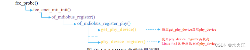
When registering the MIDO bus, it will find the PHY device from the device tree, and then register the PHY device with the kernel through the phy_device_register function. Next, let's learn about the PHY subsystem.
3. Brief analysis of fec_drv_remove function
The fec_drv_remove function will be executed when the I.MX6ULL network driver is uninstalled. The content of the function is as follows:
1 static int fec_drv_remove(struct platform_device *pdev)
2 {
3      struct net_device *ndev = platform_get_drvdata(pdev);
4      struct fec_enet_private *fep = netdev_priv(ndev);
5
6      cancel_delayed_work_sync(&fep->time_keep);
7      cancel_work_sync(&fep->tx_timeout_work);
8      unregister_netdev(ndev);
9      fec_enet_mii_remove(fep);
10     if (fep->reg_phy)
11       regulator_disable(fep->reg_phy);
12     if (fep->ptp_clock)
13         ptp_clock_unregister(fep->ptp_clock);
14      of_node_put(fep->phy_node);
15     free_netdev(ndev);
16
17    return 0;
18 }
In line 8, call the unregister_netdev function to cancel the previously registered net_device.
Line 9, call the fec_enet_mii_remove function to remove the MDIO bus-related content, this function will call mdiobus_unregister to unregister mii_bus, and release mii_bus through the function mdiobus_free
In line 15, call the free_netdev function to release the previously applied net_device.
4. fec_netdev_ops operation set
The fec_probe function sets the net_dev_ops operation set of the network card driver to fec_netdev_ops, and the content of fec_netdev_ops is as follows:
1 static const struct net_device_ops fec_netdev_ops = {
2         .ndo_open = fec_enet_open,
3         .ndo_stop = fec_enet_close,
4         .ndo_start_xmit = fec_enet_start_xmit,
5         .ndo_select_queue = fec_enet_select_queue,
6         .ndo_set_rx_mode = set_multicast_list,
7         .ndo_change_mtu = eth_change_mtu,
8         .ndo_validate_addr = eth_validate_addr,
9         .ndo_tx_timeout = fec_timeout,
10        .ndo_set_mac_address = fec_set_mac_address,
11        .ndo_do_ioctl = fec_enet_ioctl,
12 #ifdef CONFIG_NET_POLL_CONTROLLER
13        .ndo_poll_controller = fec_poll_controller,
14 #endif
15        .ndo_set_features = fec_set_features,
16 };
Brief analysis of fec_enet_open function
The fec_enet_open function will be executed when a network card is opened. The source code of the function is as follows (limited to space, some are omitted):
            示例代码 fec_enet_open 函数
1 static int fec_enet_open(struct net_device *ndev)
2 {
3       struct fec_enet_private *fep = netdev_priv(ndev);
4       const struct platform_device_id *id_entry =
5       platform_get_device_id(fep->pdev);
6       int ret;
7
8       pinctrl_pm_select_default_state(&fep->pdev->dev);
9       ret = fec_enet_clk_enable(ndev, true);
10     if (ret)
11        return ret;
12
13     /* I should reset the ring buffers here, but I don't yet know
14      * a simple way to do that.
15     */
16
17     ret = fec_enet_alloc_buffers(ndev);
18     if (ret)
19       goto err_enet_alloc;
20
21     /* Init MAC prior to mii bus probe */
22     fec_restart(ndev);
23
24     /* Probe and connect to PHY when open the interface */
25     ret = fec_enet_mii_probe(ndev);
26     if (ret)
27     goto err_enet_mii_probe;
28
29     napi_enable(&fep->napi);
30     phy_start(fep->phy_dev);
31     netif_tx_start_all_queues(ndev);
32
......
47
48     return 0;
49
50    err_enet_mii_probe:
51    fec_enet_free_buffers(ndev);
52    err_enet_alloc:
53    fep->miibus_up_failed = true;
54    if (!fep->mii_bus_share)
55    pinctrl_pm_select_sleep_state(&fep->pdev->dev);
56    return ret;
57 }
Line 9, call the fec_enet_clk_enable function to enable the enet clock.
In line 17, call the fec_enet_alloc_buffers function to apply for the ring buffer buffer. In this function, the two functions fec_enet_alloc_rxq_buffers and fec_enet_alloc_txq_buffers are called to realize the application of the send queue and receive queue buffer respectively.
Line 22, restarting the network, generally calls the fec_restart function when the connection status changes, the transmission times out, or the network is configured.
Line 25, when opening the network card, call the fec_enet_mii_probe function to detect and connect to the corresponding PHY device.
On line 29, call the napi_enable function to enable NAPI scheduling.
Line 30, call the phy_start function to start the PHY device.
Line 31, call the netif_tx_start_all_queues function to activate the send queue.
Brief analysis of fec_enet_close function
The fec_enet_close function will be executed when the network card is closed, and the function content is as follows:
1 static int fec_enet_close(struct net_device *ndev)
2 {
3      struct fec_enet_private *fep = netdev_priv(ndev);
4
5      phy_stop(fep->phy_dev);
6
7      if (netif_device_present(ndev)) {
8          napi_disable(&fep->napi);
9          netif_tx_disable(ndev);
10         fec_stop(ndev);
11     }
12
13    phy_disconnect(fep->phy_dev);
14    fep->phy_dev = NULL;
15
16    fec_enet_clk_enable(ndev, false);
17    pm_qos_remove_request(&fep->pm_qos_req);
18    pinctrl_pm_select_sleep_state(&fep->pdev->dev);
19    pm_runtime_put_sync_suspend(ndev->dev.parent);
20    fec_enet_free_buffers(ndev);
21
22    return 0;
23 }
Line 5, call the phy_stop function to stop the PHY device.
On line 8, call the napi_disable function to close the NAPI scheduling.
Line 9, call the netif_tx_disable function to close the NAPI send queue.
Line 10, call the fec_stop function to close the ENET peripheral of I.MX6ULL.
On line 13, call the phy_disconnect function to disconnect from the PHY device.
Line 16, call the fec_enet_clk_enable function to turn off the ENET peripheral clock.
On line 20, call the fec_enet_free_buffers function to release the sending and receiving ring buffer memory.
Brief analysis of fec_enet_start_xmit function
The network data transmission of I.MX6ULL is completed through the fec_enet_start_xmit function. This function sends the data in the sk_buff passed by the upper layer through the hardware. The source code of the function is as follows:
1 static netdev_tx_t fec_enet_start_xmit(struct sk_buff *skb,
                                      struct net_device *ndev)
2 {
3      struct fec_enet_private *fep = netdev_priv(ndev);
4      int entries_free;
5      unsigned short queue;
6      struct fec_enet_priv_tx_q *txq;
7      struct netdev_queue *nq;
8      int ret;
9
10     queue = skb_get_queue_mapping(skb);
11     txq = fep->tx_queue[queue];
12     nq = netdev_get_tx_queue(ndev, queue);
13
14     if (skb_is_gso(skb))
15       ret = fec_enet_txq_submit_tso(txq, skb, ndev);
16    else
17      ret = fec_enet_txq_submit_skb(txq, skb, ndev);
18    if (ret)
19      return ret;
20
21    entries_free = fec_enet_get_free_txdesc_num(fep, txq);
22    if (entries_free <= txq->tx_stop_threshold)
23         netif_tx_stop_queue(nq);
24
25    return NETDEV_TX_OK;
26 }
Parameters of this function The first parameter skb is the network data to be sent from the upper layer application, and the second parameter ndev is the device to send the data.
Line 14, judge whether skb is GSO (Generic Segmentation Offload), if it is GSO, send it through fec_enet_txq_submit_tso function, if not, send it through fec_enet_txq_submit_skb. Here is a brief introduction to TSO and GSO:
TSO: The full name is TCP Segmentation Offload, which uses the network card to automatically segment large data packets to reduce CPU load.
GSO: The full name is Generic Segmentation Offload. Before sending data, check whether the network card supports TSO. If it supports it, the network card will be segmented. If it is not supported, the protocol stack will perform segmentation processing. NIC to send.
In line 21, get the number of remaining transmit descriptors through the fec_enet_get_free_txdesc_num function.
On line 23, if the number of remaining send descriptors is less than the set threshold (tx_stop_threshold), call the function netif_tx_stop_queue to suspend sending, and notify the application layer to stop sending skb to the network by suspending sending, and it will be restarted during sending interruption.
Brief analysis of fec_enet_interrupt interrupt service function
As mentioned above, the network data reception of I.MX6ULL adopts the NAPI framework, so interrupts must be used. The fec_probe function will initialize the network interrupt, the interrupt service function is fec_enet_interrupt, the function content is as follows:
1 static irqreturn_t fec_enet_interrupt(int irq, void *dev_id)
2 {
3      struct net_device *ndev = dev_id;
4      struct fec_enet_private *fep = netdev_priv(ndev);
5      uint int_events;
6      irqreturn_t ret = IRQ_NONE;
7
8      int_events = readl(fep->hwp + FEC_IEVENT);
9      writel(int_events, fep->hwp + FEC_IEVENT);
10     fec_enet_collect_events(fep, int_events);
11
12     if ((fep->work_tx || fep->work_rx) && fep->link) {
13        ret = IRQ_HANDLED;
14
15           if (napi_schedule_prep(&fep->napi)) {
16             /* Disable the NAPI interrupts */
17            writel(FEC_ENET_MII, fep->hwp + FEC_IMASK);
18             __napi_schedule(&fep->napi);
19           }
20     }
21
22    if (int_events & FEC_ENET_MII) {
23       ret = IRQ_HANDLED;
24      complete(&fep->mdio_done);
25    }
26
27   if (fep->ptp_clock)
28   fec_ptp_check_pps_event(fep);
29
30   return ret;
31 }
It can be seen that the interrupt service function is very short! And I haven't seen the processing process of data reception, that's because the network driver of I.MX6ULL uses NAPI, and the specific network data transmission and reception is completed in the poll function of NAPI, and only napi scheduling is needed in the interrupt. This is the upper and lower half of the interrupt processing mechanism.
Line 8, read the interrupt status register EIR of NENT to get the interrupt status.
In line 9, the interrupt status value obtained in line 8 is written into the EIR register to clear the interrupt status register.
On line 10, call the fec_enet_collect_events function to count interrupt information, that is, to count which interrupts have occurred. The bit0, bit1 and bit2 of the member variables work_tx and work_rx in fep are used to make different marks, the bit2 of work_rx indicates that the data frame is received, and the bit2 of work_tx indicates that the data frame has been sent.
On line 15, call the napi_schedule_prep function to check whether NAPI can schedule.
In line 17, if the relevant interrupts are enabled, these interrupts must be closed first, and the relevant interrupts can be closed by writing 1 to bit23 of the EIMR register.
In line 18, call the __napi_schedule function to start NAPI scheduling. At this time, the poll function of napi will be executed, which is the fec_enet_rx_napi function in this network driver.
Brief analysis of fec_enet_rx_napi interrupt service function
When the fec_enet_init function initializes the network, it will call netif_napi_add to set the NAPI poll function as fec_enet_rx_napi. The function content is as follows:
1 static int fec_enet_rx_napi(struct napi_struct *napi, int budget)
2 {
3        struct net_device *ndev = napi->dev;
4        struct fec_enet_private *fep = netdev_priv(ndev);
5        int pkts;
6
7        pkts = fec_enet_rx(ndev, budget);
8
9        fec_enet_tx(ndev);
10
11       if (pkts < budget) {
12               napi_complete(napi);
13            writel(FEC_DEFAULT_IMASK, fep->hwp + FEC_IMASK);
14        }
15       return pkts;
16 }
On line 7, call the fec_enet_rx function for real data reception.
Line 9, call fec_enet_tx function to send data.
On line 12, the napi_complete function is called to announce the end of a poll.
Line 13, set the EIMR register of ENET and re-enable the interrupt.
Brief Analysis of Linux Kernel PHY Subsystem and MDIO Bus
As mentioned in the previous section when explaining the MDIO bus, when registering the MDIO bus, the PHY device will also be registered with the kernel. In this section, we will briefly understand the PHY subsystem. The PHY subsystem is used for PHY device-related content. It is divided into PHY devices and PHY drivers. Like the platform bus, the PHY subsystem is also a device, bus, and driver model.
1. PHY equipment
First look at the PHY device. The Linux kernel uses the phy_device structure to represent the PHY device. The structure is defined in include/linux/phy.h. The content of the structure is as follows:
1 struct phy_device {
2      /* Information about the PHY type */
3      /* And management functions */
4      struct phy_driver *drv; /* PHY 设备驱动 */
5      struct mii_bus *bus; /* 对应的 MII 总线 */
6      struct device dev; /* 设备文件 */
7      u32 phy_id; /* PHY ID */
8
9      struct phy_c45_device_ids c45_ids;
10     bool is_c45;
11     bool is_internal;
12     bool has_fixups;
13     bool suspended;
14
15     enum phy_state state; /* PHY 状态 */
16     u32 dev_flags;
17     phy_interface_t interface; /* PHY 接口 */
18
19     /* Bus address of the PHY (0-31) */
20     int addr; /* PHY 地址(0~31) */
21
22     /*
23      * forced speed & duplex (no autoneg)
24      * partner speed & duplex & pause (autoneg)
25     */
26     int speed; /* 速度 */
27     int duplex; /* 双共模式 */
28     int pause;
29     int asym_pause;
30
31     /* The most recently read link state */
32     int link;
33
34     /* Enabled Interrupts */
35     u32 interrupts; /* 中断使能标志 */
36
37     /* Union of PHY and Attached devices' supported modes */
38     /* See mii.h for more info */
39     u32 supported;
40     u32 advertising;
41     u32 lp_advertising;
42     int autoneg;
43     int link_timeout;
44
45     /*
46      * Interrupt number for this PHY
47      * -1 means no interrupt
48     */
49    int irq; /* 中断号 */
50
51    /* private data pointer */
52    /* For use by PHYs to maintain extra state */
53    void *priv; /* 私有数据 */
54
55    /* Interrupt and Polling infrastructure */
56    struct work_struct phy_queue;
57    struct delayed_work state_queue;
58    atomic_t irq_disable;
59    struct mutex lock;
60    struct net_device *attached_dev; /* PHY 芯片对应的网络设备 */
61    void (*adjust_link)(struct net_device *dev);
62 };
A PHY device corresponds to a phy_device instance, and then this instance needs to be registered with the Linux kernel. Use the phy_device_register function to complete the registration of the PHY device. The function prototype is as follows:
int phy_device_register(struct phy_device *phy)
Function parameters and return values have the following meanings:
phy: The PHY device that needs to be registered.
Return value: 0 for success, negative values for failure.
The registration process of the PHY device is generally to call the get_phy_device function to obtain the PHY device. The content of this function is as follows:
1 struct phy_device *get_phy_device(struct mii_bus *bus, int addr,
                                   bool is_c45)
2 {
3      struct phy_c45_device_ids c45_ids = {0};
4      u32 phy_id = 0;
5      int r;
6
7      r = get_phy_id(bus, addr, &phy_id, is_c45, &c45_ids);
8      if (r)
9      return ERR_PTR(r);
10
11     /* If the phy_id is mostly Fs, there is no device there */
12     if ((phy_id & 0x1fffffff) == 0x1fffffff)
13       return NULL;
14
15    return phy_device_create(bus, addr, phy_id, is_c45, &c45_ids);
16 }
In line 7, call the get_phy_id function to obtain the PHY ID, that is, read the two ID registers of the PHY chip to obtain the PHY chip ID information.
Line 15 calls the phy_device_create function to create a phy_device. This function first applies for phy_device memory, then initializes each structure member of phy_device, and finally returns the created phy_device. The phy_device_register function registers the created phy_device.
2. PHY driver
The PHY driver is represented by the structure phy_driver, which is also defined in the include/linux/phy.h file. The content of the structure is as follows (in order to reduce the space, the comment part is omitted):
1 struct phy_driver {
2     u32 phy_id; /* PHY ID */
3     char *name;
4     unsigned int phy_id_mask; /* PHY ID 掩码 */
5     u32 features;
6     u32 flags;
7     const void *driver_data;
8
9     int (*soft_reset)(struct phy_device *phydev);
10    int (*config_init)(struct phy_device *phydev);
11    int (*probe)(struct phy_device *phydev);
12    int (*suspend)(struct phy_device *phydev);
13    int (*resume)(struct phy_device *phydev);
14    int (*config_aneg)(struct phy_device *phydev);
15    int (*aneg_done)(struct phy_device *phydev);
16    int (*read_status)(struct phy_device *phydev);
17    int (*ack_interrupt)(struct phy_device *phydev);
18    int (*config_intr)(struct phy_device *phydev);
19    int (*did_interrupt)(struct phy_device *phydev);
20    void (*remove)(struct phy_device *phydev);
21    int (*match_phy_device)(struct phy_device *phydev);
22    int (*ts_info)(struct phy_device *phydev,
                       struct ethtool_ts_info *ti);
23    int (*hwtstamp)(struct phy_device *phydev, struct ifreq *ifr);
24    bool (*rxtstamp)(struct phy_device *dev, struct sk_buff *skb,
                  int type);
25    void (*txtstamp)(struct phy_device *dev, struct sk_buff *skb,
                   int type);
26    int (*set_wol)(struct phy_device *dev,
                     struct ethtool_wolinfo *wol);
27    void (*get_wol)(struct phy_device *dev,
                              struct ethtool_wolinfo *wol);
28    void (*link_change_notify)(struct phy_device *dev);
29    int (*read_mmd_indirect)(struct phy_device *dev, int ptrad,
30                        int devnum, int regnum);
31    void (*write_mmd_indirect)(struct phy_device *dev, int ptrad,
32    int devnum, int regnum, u32 val);
33    int (*module_info)(struct phy_device *dev,
34    struct ethtool_modinfo *modinfo);
35    int (*module_eeprom)(struct phy_device *dev,
36    struct ethtool_eeprom *ee, u8 *data);
37
38     struct device_driver driver;
39 };
It can be seen that the focus of phy_driver is a large number of functions. The main task of writing a PHY driver is to implement these functions, but not necessarily all of them. Later we will briefly analyze the general PHY driver of the Linux kernel.
①. Register PHY driver
After the phy_driver structure is initialized, it needs to register with the Linux kernel. The registration of the PHY driver uses the phy_driver_register function. When registering the phy driver, the bus of the driver will be set to mdio_bus_type, which is the MDIO bus. The MDIO bus will be explained later, and the function prototype as follows:
int phy_driver_register(struct phy_driver *new_driver)
Function parameters and return values have the following meanings:
new_driver: The PHY driver that needs to be registered.
Return value: 0 for success, negative values for failure.
②. Continuously register multiple PHY drivers
A manufacturer will produce a variety of PHY chips, and the internal differences of these PHY chips are generally not large. If you register drivers one by one, it will result in a bunch of duplicate driver files. Therefore, the Linux kernel provides a function phy_drivers_register that continuously registers multiple PHY drivers. . First prepare a phy_driver array, an array element represents the driver of a PHY chip, and then call phy_drivers_register to register all drivers in the entire array at one time, the function prototype is as follows:
int phy_drivers_register(struct phy_driver *new_driver, int n)
Function parameters and return values have the following meanings:
new_driver: An array of multiple PHY drivers that need to be registered.
n: The number of drivers to register.
Return value: 0 for success, negative values for failure.
③. Uninstall the PHY driver
To uninstall the PHY driver, use the phy_driver_unregister function, the function prototype is as follows:
void phy_driver_unregister(struct phy_driver *drv)
Function parameters and return values have the following meanings:
new_driver: The PHY driver that needs to be uninstalled.
Return value: None.
3. MDIO bus
As mentioned earlier, the PHY subsystem also follows the device, bus, and driver models. Devices and drivers are phy_device and phy_driver. The bus is the MDIO bus, because the PHY chip is managed through the MIDO interface, and the main job of the MDIO bus is to match the PHY device and the PHY driver. In the file drivers/net/phy/mdio_bus.c there are the following definitions:
1 struct bus_type mdio_bus_type = {
2      .name = "mdio_bus",
3      .match = mdio_bus_match,
4      .pm = MDIO_BUS_PM_OPS,
5      .dev_groups = mdio_dev_groups,
6 };
The sample code defines a bus named "mdio_bus_type", which is the MDIO bus, the name of the bus is "mdio_bus", and the key point is that the matching function of the bus is mdio_bus_match. The content of this function is as follows:
1 static int mdio_bus_match(struct device *dev,
                         struct device_driver *drv)
2 {
3       struct phy_device *phydev = to_phy_device(dev);
4       struct phy_driver *phydrv = to_phy_driver(drv);
5
6       if (of_driver_match_device(dev, drv))
7              return 1;
8
9       if (phydrv->match_phy_device)
10            return phydrv->match_phy_device(phydev);
11
12      return (phydrv->phy_id & phydrv->phy_id_mask) ==
13           (phydev->phy_id & phydrv->phy_id_mask);
14 }
Line 6, if using the device tree, first try to use of_driver_match_device to match the device and the driver, that is, check whether the compatible attribute value is consistent with the content in the matching table of_match_table. But for the tutorial in this chapter, the PHY driver and device matching is not done through of_driver_match_device.
Lines 9 and 10 check whether the PHY driver provides the matching function match_phy_device, and if so, directly call the matching function provided by the PHY driver to complete the matching with the device.
Lines 12 and 13, if the above two matching methods are invalid, use the last one. There are two member variables phy_id and phy_id_mask in phy_driver, indicating the PHY chip ID and ID mask matched by this driver. The PHY driver writer These two member variables need to be assigned values. phy_device also has a phy_id member variable, which indicates the ID of the PHY chip. The phy_id in phy_device is obtained by calling the get_phy_id function to directly read the internal ID register of the PHY chip when registering the PHY device! Obviously, the IDs in the PHY driver and the PHY device must be the same, so that they can match. So the last method is to compare whether the phy_id in the PHY driver is consistent with the phy_id in the PHY device. Here you need to perform an AND operation with the phy_id_mask in the PHY driver. If the result is consistent, it means that the driver and the device match.
If the PHY device and the PHY driver match, then use the specified PHY driver, if not, use the generic PHY driver that comes with the Linux kernel.
4. Universal PHY driver
As mentioned many times before, the Linux kernel has integrated the generic PHY driver. The name of the generic PHY driver is "Generic PHY". Open drivers/net/phy/phy_device.c and find the phy_init function. The content is as follows:
1 static int __init phy_init(void)
2 {
3      int rc;
4
5      rc = mdio_bus_init();
6      if (rc)
7         return rc;
8
9      rc = phy_drivers_register(genphy_driver,
10                      ARRAY_SIZE(genphy_driver));
11     if (rc)
12        mdio_bus_exit();
13
14      return rc;
15 }
phy_init is the entry function of the entire PHY subsystem. The 9th line will call the phy_drivers_register function to directly register a general PHY driver with the kernel: genphy_driver, which is the general PHY driver, which means that the general PHY driver already exists by default after the Linux system starts.
genphy_driver is an array with two array elements, indicating that there are two general PHY drivers, one for 10/100/1000M network and one for 10G network. genphy_driver is defined in drivers/net/phy/phy_device.c, the content is as follows:
1 static struct phy_driver genphy_driver[] = {
2 {
3      .phy_id = 0xffffffff,
4      .phy_id_mask = 0xffffffff,
5      .name = "Generic PHY",
6      .soft_reset = genphy_soft_reset,
7      .config_init = genphy_config_init,
8      .features = PHY_GBIT_FEATURES | SUPPORTED_MII |
9            SUPPORTED_AUI | SUPPORTED_FIBRE |
10           SUPPORTED_BNC,
11     .config_aneg = genphy_config_aneg,
12     .aneg_done = genphy_aneg_done,
13     .read_status = genphy_read_status,
14     .suspend = genphy_suspend,
15     .resume = genphy_resume,
16     .driver = { .owner = THIS_MODULE, },
17 }, {
18     .phy_id = 0xffffffff,
19     .phy_id_mask = 0xffffffff,
20    .name = "Generic 10G PHY",
21    .soft_reset = gen10g_soft_reset,
22    .config_init = gen10g_config_init,
23    .features = 0,
24    .config_aneg = gen10g_config_aneg,
25    .read_status = gen10g_read_status,
26    .suspend = gen10g_suspend,
27    .resume = gen10g_resume,
28    .driver = {.owner = THIS_MODULE, },
29 } };
The genphy_driver array has two elements, genphy_driver[0] is the 10/100/1000M PHY driver named "Generic PHY", genphy_driver[1] is the 10G PHY driver named "Generic 10G PHY". Note that many additionally written PHY drivers will also use some functions of the general PHY driver. For example, the LAN8720A used by the Atom ALPHA development board is a product of SMSC. The company has written a driver file smsc.c for all its own PHY chips. , a large number of common PHY driver-related functions are used in this driver file.
5. LAN8720A driver
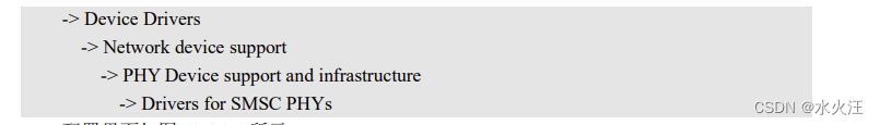
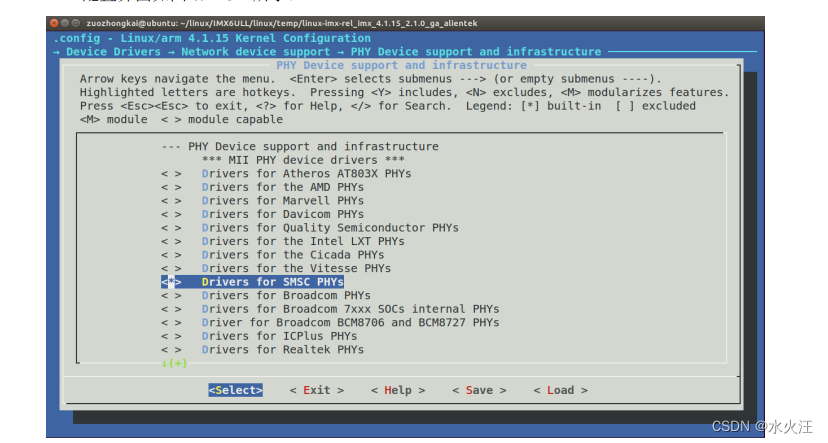
Finally, let's take a look at the Linux driver of LAN8720A. The driver file of LAN8720A is drivers/net/phy/smsc.c. This file is a driver file written by SMSC for some of its own PHY chips, which includes the PHY chip of LAN8720A. By default, the LAN8720A driver is not enabled. We need to configure the linux kernel to enable this driver option. The configuration path is as follows:
It can be seen from the sample code that smsc_phy_driver still supports many SMSC PHY chips, such as LAN83C185, LAN8187, LAN8700, etc. Of course, it must also include the LAN8720 series. Lines 93~116 are the LAN8710/LAN8720 series PHY drivers .
Line 94, PHY ID is 0X0007C0F0
In line 95, the PHY ID mask is 0XFFFFFFF0, that is, the first 28 bits are valid, and only the first 28 bits need to be compared when performing a match, and the fourth bit does not need to be compared.
In line 74, the driver name is "SMSC LAN8710/LAN8720". After the system is started, when the network card is turned on, it will prompt that the current PHY driver name is "SMSC LAN8710/LAN8720".
Finally, line 118 uses module_phy_driver (essentially a macro) to complete the registration of smsc_phy_driver. Some member functions in this driver are written by SMSC itself, and some are directly used by general PHY drivers, such as genphy_config_aneg in line 103, genphy_suspend in line 112, etc.
Network Drive Experimental Test
LAN8720 PHY Driver Test
First of all, it must be the driver modification. This has been explained in detail in section 37.4.3, just refer to the modification. After the system starts, it will print out the name of the current PHY driver as "SMSC LAN8710/LAN8720"

It can be seen from the figure that the PHY driver is using "SMSC LAN8710/8720" at this time. When we use the ifconfig command to open the network card, the current PHY driver name will also be prompted. As for the network test, it is very simple. You can ping the address of the host or ubuntu. If you can ping it, it means that the network is working normally.