When data assets need to be connected to related applications within the data stack, the types of blood relationship supported are increased from tables and offline tasks to required tables, offline tasks, real-time tasks, API tasks, indicators, tags, etc., and all existing application tasks of the data stack need to be supported, and finally a complete application link for viewing tasks on the data asset platform is realized .
Although different tasks are added, the bloodline of asset realization at this stage can generally meet the needs, but problems will also occur, so technological innovation is required. This article will focus on the implementation of asset lineage , and introduce the challenges and technical implementations encountered by Kangaroo Cloud Data Stack in the process of data lineage construction.
Current Issues with Asset Lineage
At this stage, blood relationship display content is highly repetitive
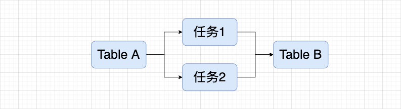
In the lineage link of task A of the asset , the downstream nodes of task C/D are all task E. When we open the downstream nodes of task C/D at the same time, we will find a large number of duplicate nodes, but in essence they are exactly the same task nodes, as shown in the figure below.
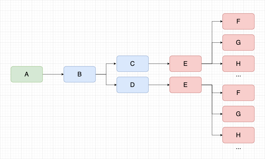
When there are more tasks on a blood relationship, the probability of the above problems increases, which will cause the content of the canvas to display duplicate nodes, and the efficiency of viewing blood relationship is low.
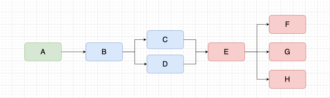
It is expected that the same node can be displayed only once in the canvas. When this node exists in the canvas, it will be shared with the same node in the future, as shown in the figure below.
Display of Reverse Bloodlines
First, let me briefly introduce, what is reverse blood relationship ? Using the API task as an example:
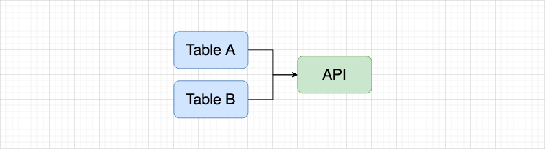
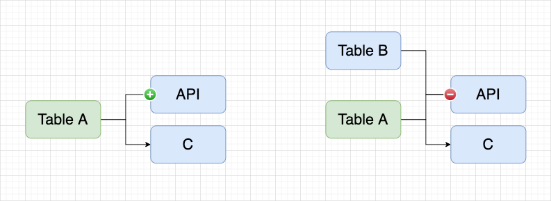
In the API platform , use two tables to create an API through the DQL mode , and enter the blood relationship with the API task on the asset platform, and the blood relationship shown in the figure below will be displayed. If Table A has been synchronized to the asset platform, use Table A to enter the blood relationship, and hope to display the blood relationship as shown in the figure below.
Since the API is jointly generated by Table A/B, it is necessary to display a plus sign on the left side of the API to load Table B. This is the reverse blood relationship and an important part of the full link implementation.
similar data sources
When the same data source is connected by different engines, different data source A or data source A1 will be generated, but in fact the bottom layer is the same data source, which we call similar data source .
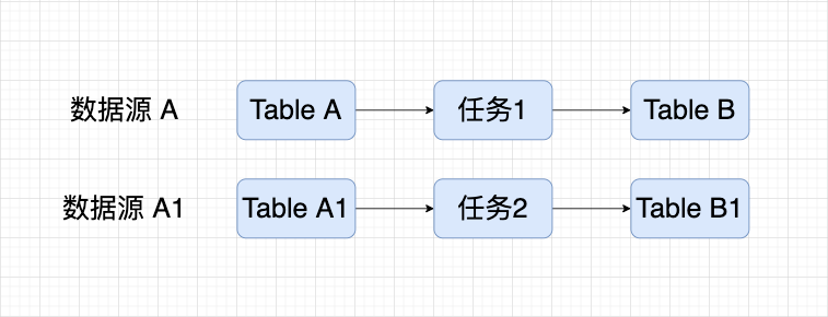
At this time, task 1 and task 2 are not related, but in fact they both use the same underlying table, and the display does not meet expectations. It is hoped that they can be treated as the same table in blood relationship display, and related tasks can also be displayed in association.
The above problems have become the reasons for the current blood relationship scheme that needs to be implemented or optimized to realize the full link blood relationship of assets. The solutions to the corresponding problems will be given below.
Asset lineage realization solution
Pre-content understanding
● Task lineage data structure
interface ITaskKinShip {
  metaId:  number;                  // 元Id
  metaType: number;                 // 元类型
  metaDataInfo: object;             // 表、api、任务、标签等的元数据信息的元数据信息
  lineageTableId:  string;          // 血缘Id
  tableKey: string;                 // 表key source.db.table
  sonIds: number[];                 // 子节点血缘定位Id list
  fatherIds: number[];              // 父节点血缘定位Id list
  sonLineage: ITaskKinShip[];       // 子表级血缘
  fatherLineage: ITaskKinShip[];    // 父表级血缘
  isOpen: boolean;                  // 是否存在逆向血缘
}
● Field lineage data structure
interface IColumn {
  columnId: string;             // 字段Id
  columnName: string;           // 字段类型
  columnType:  string;          // 字段
  lineageColumnId: string;      // 字段血缘定位Id
  withManual: boolean;          // 是否手动维护
  withMasked: boolean;          // 是否脱敏字段
  sonIds: number[];             // 子ID
  fatherIds: number[];          // 父ID
  columnKey: string;            // 字段key source.db.table.column
}

interface IColumnKinShip extends ITaskKinShip {
  columns: IColumn[];           // 字段血缘
}
● blood relationship diagram
3 layers are displayed by default during initialization: that is, only the node of the data table is displayed as the center, and the upstream and downstream nodes are respectively displayed, a total of 3 layers
Nodes can be expanded: click the "+" button to display 3 more nodes in front or behind the node; click the "-" button to disconnect the connection corresponding to the "-" button
· Right-click: On a non-central node, add a right-click menu "View this node's lineage"; right-click to view the current node's lineage, and the lineage centered on this node
the whole idea
● Realize node sharing
If we want to achieve node sharing , we will judge whether the current node already exists in the graph. If it exists, we will no longer render the node, otherwise we will render the node, so that the node can only be rendered once.
For each node information, tableKey is unique, so we use tableKey as the unique identifier of each vertex, and pass in tableKey as the unique identifier when creating a vertex.
createVertex = (treeData) => {
    const { graph, Mx } = this.GraphEditor;
    const rootCell = graph.getDefaultParent();
    const style = this.GraphEditor.getStyles(treeData);
    const doc = Mx.mxUtils.createXmlDocument();
    const tableInfo = doc.createElement('table');
    const { vertex, fatherLineage, sonLineage, ...newData } = treeData;
    tableInfo.setAttribute('data', JSON.stringify(newData));
    // 通过 tableKey 在当前 graph 查找 vertex
    const cell = graph.getModel().getCell(treeData.tableKey);
    // 如果能够找到就不创建新的 vertex,否则创建
    const newVertex =
        cell ||
        graph.insertVertex(
            rootCell,
            treeData.tableKey,
            tableInfo,
            20,
            20,
            VertexSize.width,
            VertexSize.height,
            style
        );
    return { rootCell, style, vertex: newVertex };
}
If we adopt the above idea, then this node can become the upstream node and the subordinate node of the central node at the same time, or even the central node. Therefore, we need to change the structure of our storage nodes, and we need to store the information of the node as the upstream node and the information of the lower node.
After the data is requested from the backend, we need to sort out the data and no longer store it in the state, but store it in a Map object named vertexMap with tableKey as the key. Subsequent rendering objects are also rendered according to the vertexMap.
The definition of vertexMap is as follows, which is mainly used to store node information whose tableKey is the key value.
vertexMap = new Map<
    string,
    {
        rootData?: ITaskKinShip;      // 节点作为根节点存储的数据
        parentData?: ITaskKinShip;    // 节点作为上游节点存储的数据
        childData?: ITaskKinShip;     // 节点作为下游节点存储的数据
        canDeleteData?: any;          // 能够被删除的数据,用于删除的时候判断
    }
>()
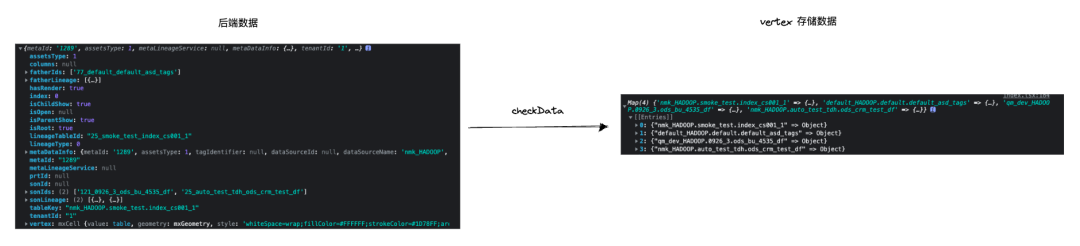
Use the checkData method to process the data given by the backend into the vertexMap. The key point is to integrate the data that are both upstream nodes or downstream nodes.
checkData = (treeData: ITaskKinShip) => {
    const {
        tableKey,
        isRoot = false,
        isParent,
        sonIds,
        fatherIds,
        sonLineage,
        fatherLineage,
    } = treeData;
    const mapData = this.vertexMap.get(tableKey);
    // 标识为根结点
    if (mapData?.rootData) return true;
    // 判断是上游节点还是下游节点
    const newKey = isRoot ? 'rootData' : isParent ? 'parentData' : 'childData';
    // 如果不存在上游节点/下有节点的数据直接赋值
    if (!mapData?.[newKey])
        return this.vertexMap.set(tableKey, { ...mapData, [newKey]: treeData });
    // 否则,需要整合相同节点的 sonIds/fatherIds sonLineage/fatherLineage,为后续的判断提供依据
    const nodeData = mapData[newKey];
    const {
        sonIds: exitSonIds,
        fatherIds: exitFatherIds,
        fatherLineage: exitFatherLineage,
        sonLineage: exitSonLineage,
    } = nodeDat
    nodeData.sonIds = [...new Set(sonIds.concat(exitSonIds).filter((id) => id !== 'exist'))];
    nodeData.fatherIds = [
        ...new Set(fatherIds.concat(exitFatherIds).filter((id) => id !== 'exist')),
    ];
    nodeData.sonLineage = [...new Set(sonLineage.concat(exitSonLineage))];
    nodeData.fatherLineage = [...new Set(fatherLineage.concat(exitFatherLineage))];
    nodeData.isChildShow = nodeData.isChildShow || treeData.isChildShow;
    nodeData.isParentShow = nodeData.isParentShow || treeData.isParentShow;
    this.vertexMap.set(tableKey, { ...mapData, [newKey]: nodeData });
};
The above is the processing of blood relationship data, and the whole blood relationship graph node is as follows:
● How to control node expansion
When each of our nodes is rendered, there may be buttons to expand more nodes in the upper and lower layers. Due to node sharing and the need to support reverse lineage, the state of the button will change:
· The center node will not have a button
When the downstream node of the central node has downstream blood relationship, there is a right button; when there is reverse blood relationship, there is a left button
When the upstream node of the central node has upstream blood relationship, there is a left button; when there is a reverse blood relationship, there is a right button
Pay attention to whether there is a reverse blood relationship, and judge it through the isOpen flag of the back-end interface .
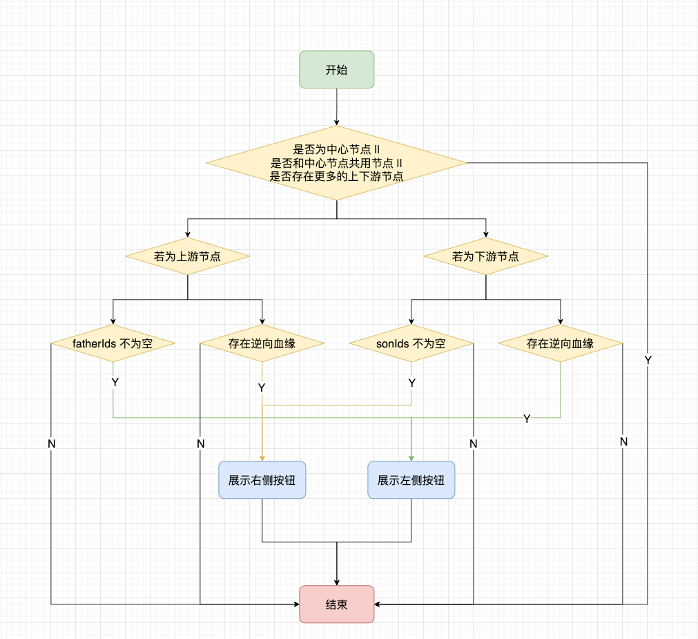
For the ordinary + sign, when you click the + sign, three layers of data will be requested at one time; for the reverse bloodline + sign, one layer of data will be requested at one time; for the - sign, all subsequent nodes will be collected.
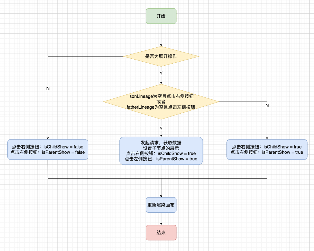
For each node, we will add isParentShow/isChildShow to indicate whether the upstream and downstream of the current node are expanded.
· Collapse operation: If the clicked button is in the expanded state, the associated node will be collapsed. When clicking the right button, set isChildShow = false for the current node; when clicking the left button, set isParentShow = false for the current node.
· Expand operation: If the clicked button is in the collapsed state, the associated node will be expanded. When clicking the button on the right, if there is no sonLineage , it means that the blood node information has not been obtained , and a request is made to the backend; otherwise, set isChildShow = true for the current node. The same is true for the left button.
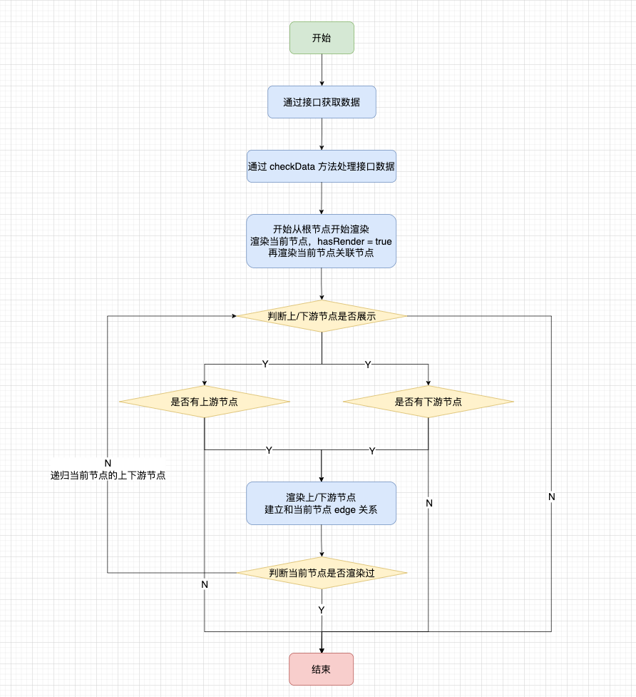
The relevant judgment process is as follows:
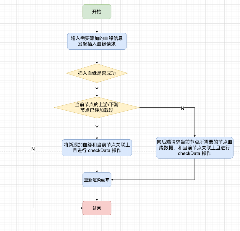
● How to handle adding/deleting nodes
We can use the right button to insert blood relationship table or insert impact table. When we do the blood relationship insertion operation, there are also two situations. It is judged whether the current node has loaded the upstream and downstream nodes. If it has been loaded, the new blood relationship data is directly added to the vertexMap; otherwise, a request is made to the backend to obtain the blood relationship data of the current node.
For deleting a node, it is no longer possible to find its parent node and delete the corresponding node before re-rendering the canvas. For node sharing, this will cause problems. On the asset platform , blood relationship nodes are divided into two types, one is parsed by sqlParser and cannot be manually deleted; the other is manually added by right-clicking and can be deleted.
When we encounter the sharing of manually added and parsed nodes, we need special processing to delete them, and retain the relevant information of the parsed nodes.
When we insert a node, we will know whether it is parsed or added manually according to the back-end flag withManual, and use canDeleteData to maintain the parent information of the manually added node .
if (withManual) {
    canDeleteData.push({
        lineageTableId: obj.lineageTableId,
        parentTableKey: obj.tableKey,
    });
}
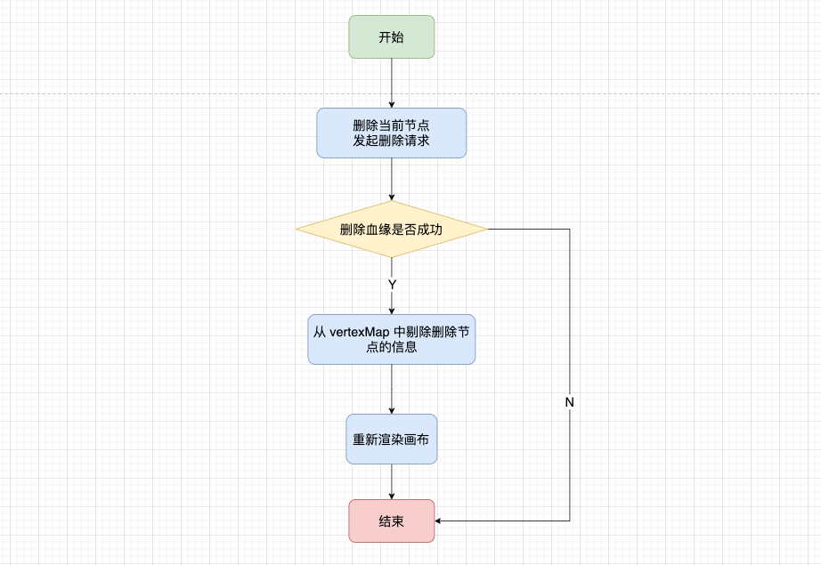
When we implemented node sharing at the beginning, we integrated the sonIds/sonLineage and other information of the same node through the checkData method. When deleting, we should cooperate with canDeleteData to clean up the corresponding data.
The general flow of the delete operation is as follows:
● Handle special types of nodes
Due to the blood relationship display of various applications, there are some special nodes. The conventional solution cannot meet the node display requirements, so special processing is required.
For real-time FlinkSQL, special processing is required. The dotted line box is the relevant content of FlinkSQL, and the nodes connected to the mapping source table and mapping result table need to be connected with dotted lines.
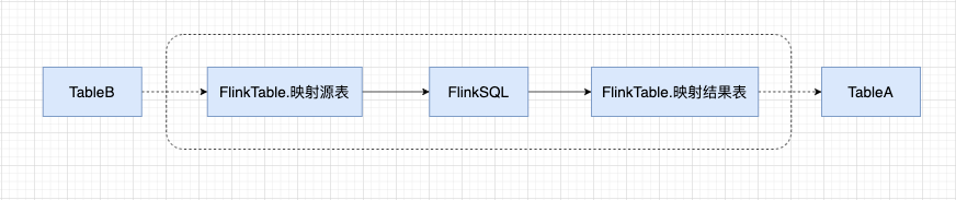
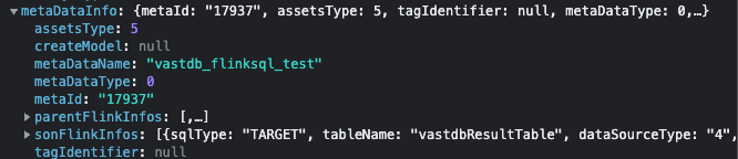
The relevant data backend of FlinkSQL is stored in metaDataInfo, parentFlinkInfos represents the mapping source table, and sonFlinkInfos represents the mapping result table.
Therefore, depending on the location of FlinkSQL, there will be different rendering logic:
· Central node
Render parentFlinkInfos to create parentFlinkTableNode and FlinkSQL node solid line connection, parentFlinkTableNode and upstream node use dotted line connection; rendering sonFlinkInfos create sonFlinkTableNode and FlinkSQL node solid line connection, created sonFlinkTableNode and downstream node use dotted line connection.
· Upstream nodes
Render sonFlinkInfos Create sonFlinkTableNode to connect with current node with dotted line, render FlinkSQL node to connect with sonFlinkTableNode with solid line, render parentFlinkInfos to create parentFlinkTableNode to connect with FlinkSQL node with solid line, and parentFlinkTableNode to use dotted line to connect with other upstream nodes.
· Downstream nodes
Render parentFlinkInfos to create parentFlinkTableNode to connect with the current node with dotted lines, render FlinkSQL nodes to connect with parentFlinkTableNode with solid lines, render sonFlinkInfos to create sonFlinkTableNode to connect with FlinkSQL nodes with solid lines, and sonFlinkTableNode to connect with other downstream nodes with dotted lines.
● similar data sources
On similar data sources, the front end has not processed them, and the back end judges them as similar data sources and presents them to the front end for related display.
● Field-level lineage
The above mentioned is the realization of table-level blood relationship, and the field-level blood relationship also realizes functions such as node sharing, and the overall idea is consistent with that of table-level blood relationship. The only thing to pay attention to is the real-time field blood relationship. If there are two result tables, there will be multiple central nodes, so it is necessary to traverse and render two central nodes.
"Dutstack Product White Paper": https://www.dtstack.com/resources/1004?src=szsm
"Data Governance Industry Practice White Paper" download address: https://www.dtstack.com/resources/1001?src=szsm If you want to know or consult more about Kangaroo Cloud's big data products, industry solutions, and customer cases, visit Kangaroo Cloud's official website: https://www.dtstack.com/?src=szkyzg
At the same time, students who are interested in big data open source projects are welcome to join "Kangaroo Cloud Open Source Framework DingTalk Technology qun" to exchange the latest open source technology information, qun number: 30537511, project address: https://github.com/DTStack
RustDesk 1.2: Using Flutter to rewrite the desktop version, supporting Wayland accused of deepin V23 successfully adapting to WSL 8 programming languages with the most demand in 2023: PHP is strong, C/C++ demand slows down React is experiencing the moment of Angular.js? CentOS project claims to be "open to everyone" MySQL 8.1 and MySQL 8.0.34 are officially released Rust 1.71.0 stable version is released