transport layer protocol
TCP: A connection-oriented, reliable transport layer communication protocol defined by RFC/93 of the IETF.
UDP: A simple connectionless transport layer protocol defined by RFC 768 of the IETF.
TCP message
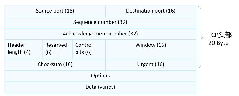
- The TCP header defaults to 20Byte (160 bits)
- The interface can only send 1500 bytes at a time, MTU=1500
- The longest TCP header is 60 Byte
Introduction to message content
-
- Source port(16): source port
- Destination port(16): destination port
- Sequence number(32): serial number, the number of the sent data
- Acknowledgment number(32): Acknowledgment number, which message has been received (indicates which sequence number the next message should start from.)
- Header length (4): The length of the header. When decapsulating, the range of the TCP header can be determined according to the length of the header.
- Reserved(6): Reserved field, no development, no use
- Options: Supplementary functions, you can add other functions (authentication, password), 0-40 Byte
- Window (16): Sliding window, used for flow control and management of current transmission volume
- Checksum(16): checksum, to see if the data is the same as before
- Urgent (16): Urgent pointer bit, when this is received, it needs to be sent to the upper layer as soon as possible
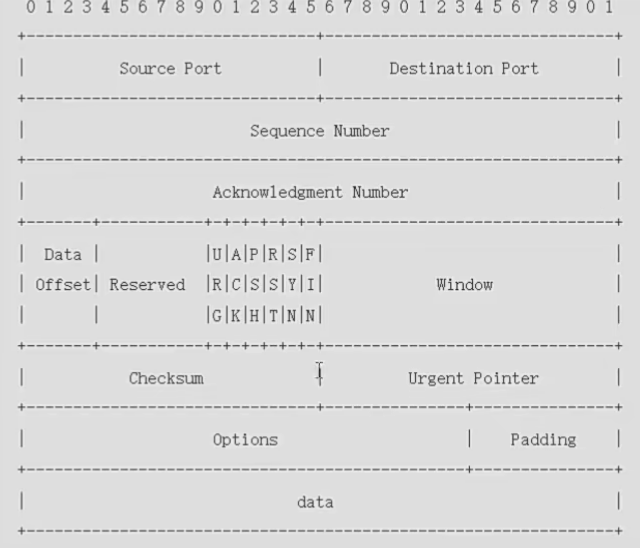
- Control bits (6): Usually called flag bit, flag bit. It can accommodate 6 bits, the value inside represents the switch, and 1 represents open;
-
-
- ACK: Valid identification of the acknowledgment sequence number, and the acknowledgment number field is valid only when ACK=1. When ACK=0, the acknowledgment number is invalid. confirm connection
- RST: Rebuild Connection ID. When RST=1, it indicates that there is a serious error in the TCP connection (such as due to a host crash or other reasons) and then the connection is re-established. reconnect
- SYN: Synchronization sequence number identification, used to initiate a connection. SYN=1 indicates that this is a connection request or connection acceptance request. establish connection
- FIN: The sender completes sending task identifier. Used to release a connection. FIN=1 indicates that the data of this segment has been sent. disconnect
- PSH: Indicates that this segment should be handed over to the application layer as soon as possible.
- URG: Urgent pointer valid representation. It tells the system that there is urgent data in this segment and should be sent as soon as possible
-
TCP establishment - three-way handshake
- Any TCP-based application, before sending data, requires TCP to perform a "three-way handshake" to establish a connection.
- The detailed process of TCP connection establishment is as follows:
-
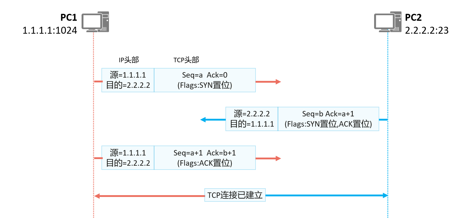
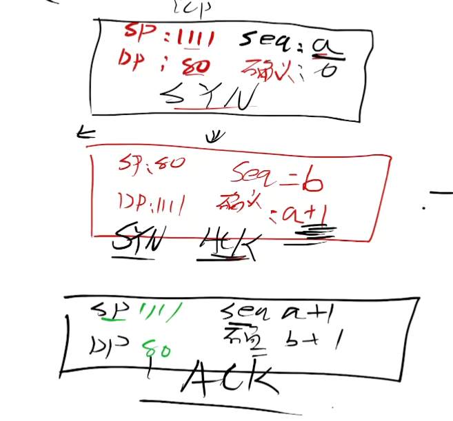
- The initiator of the TCP connection (PC1 in the figure) sends the first TCP message with the SYN bit set. The initial serial number a is a randomly generated number, because no message from PC2 has been received, so the confirmed serial number is 0;
- After receiving the legal SYN message, the receiver (PC2 in the figure) replies with a TCP message with SYN and ACK set to 1. The initial sequence number b is a randomly generated number, and because this message is a message replying to PC1, the confirmation sequence number is a+1;
- After PC1 receives the TCP message with SYN and ACK set sent by PC2, it replies with a message with ACK set. At this time, the sequence number is a+1, and the confirmation sequence number is b+1. After PC2 receives it, a TCP bidirectional connection is established.
TCP sequence number and confirmation sequence number
- TCP uses the sequence number and acknowledgment sequence number fields to achieve reliable and ordered transmission of data.
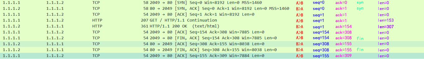
- What is the confirmation number on the opposite side of the serial number, and what is your own serial number (if you get your own serial number by calculation, then add the length of the message to your own serial number last time; Note: if you are in the three-way handshake and four times Waving your hand, if there is syn or fin, you will also get +1)
- The confirmation number is determined according to the opposite packet (the opposite serial number + [+1 if there is syn or fin] + message length)
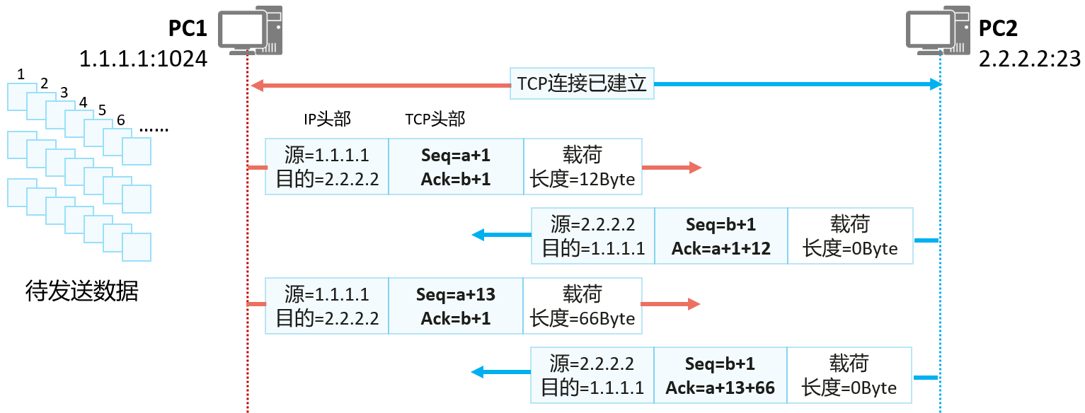
Assuming that PC1 wants to send a piece of data to PC2, the transmission process is as follows:
- PC1 numbers all the data to be sent by TCP in units of bytes. Suppose the number of the first byte is "a+1", the sequence number of the second byte is "a+2", and so on.
- PC1 will use the number of the first byte of each piece of data as the sequence number (Sequence number), and then send the TCP message.
- After PC2 receives the TCP message sent by PC1, it needs to give confirmation and request the next piece of data. How to determine the next piece of data? Serial number ( a+1 ) + payload length = serial number of the first byte of the next piece of data (a+1+12)
- After PC1 receives the TCP message sent by PC2, it finds that the confirmation sequence number is "a+1+12", indicating that the data from "a+1" to "a+12" has been accepted and needs to be transferred from "a+1" to "a+12". 1+12” to start sending.
In order to improve the sending efficiency, it is also possible to send multiple pieces of data at one time, which will be confirmed by the receiver.
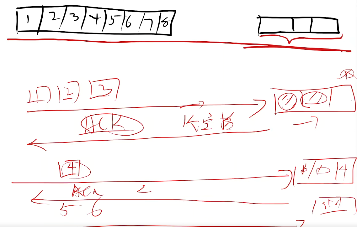
TCP window sliding mechanism
- TCP controls the data transmission rate through the sliding window mechanism
- MSS is how many bytes a window can store, the default is 1460 bytes
- If the second window transmits an error, then it needs to be retransmitted from the second window onwards
- See how many spaces are left on the opposite side, send a few spaces
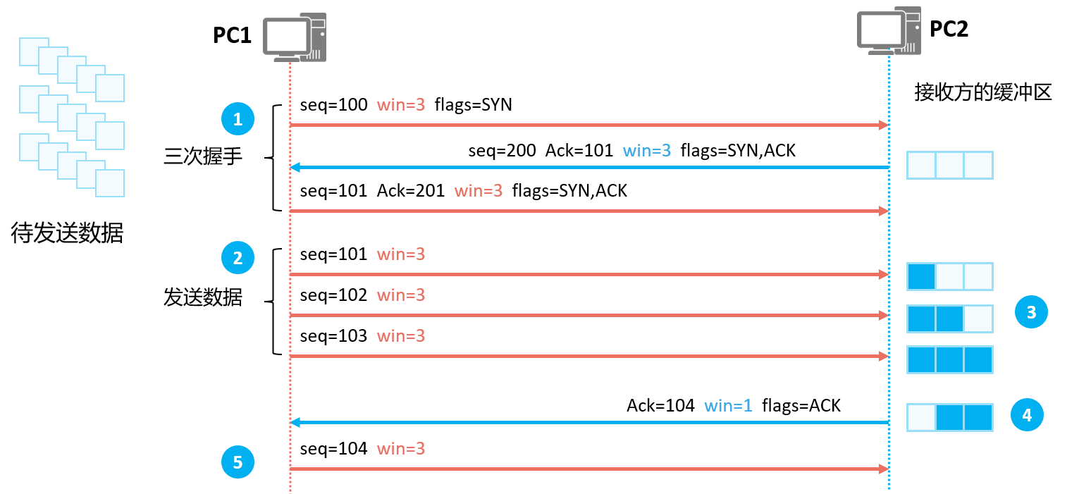
- When the TCP three-way handshake establishes a connection, both parties will tell the other party the maximum number of bytes (that is, the buffer size) that the local end can accept through the Window field.
- After the connection is successfully established, the sender will send the corresponding number of bytes of data according to the Window size announced by the receiver.
- After receiving the data, the receiver will put it in the buffer and wait for the upper layer application to take away the buffered data. If the data is taken away by the upper layer, the corresponding buffer space will be released.
- The receiver notifies the current acceptable data size ( Window ) according to its own cache space.
- The sender sends the corresponding amount of data according to the current Window size of the receiver.
Closing of TCP - "Four Waves"
- When the data transmission is completed, TCP needs to disconnect the TCP connection through the "four wave" mechanism to release system resources.
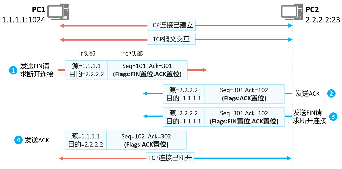
TCP supports full-duplex mode to transmit data, which means that data can be transmitted in both directions at the same time. Before transmitting data, TCP actually establishes a connection in two directions through the three-way handshake, so after the transmission is completed, the connection in both directions must be closed. as the picture shows:
- A TCP segment without data is sent by PC1 with the FIN field set to "1";
- After PC2 receives the TCP message with FIN set from PC1, it will reply a TCP message with ACK set.
- If PC2 also has no data to send, it will directly send the TCP message with FIN set. Assuming that PC2 still has data to send at this time, after PC2 sends the data, it will send a TCP message with FIN set to close the connection.
- PC1 receives the TCP message with the FIN set, replies with an ACK message, and the TCP two-way connection is disconnected.
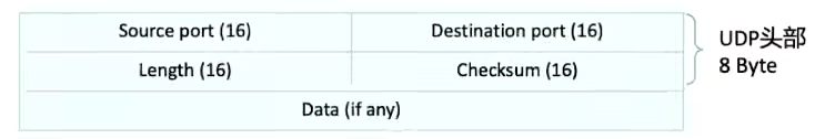
UDP packets
- connectionless service
- General video voice chat needs to use UDP
- UDP packet header:
-
- Source Port: The source port, which identifies which application sends. The length is 16 bits.
- Destination Port: The destination port, which identifies which application receives it. The length is 16 bits.
- Length: This field specifies the total length of the UDP header and data. The smallest possible length is 8 bytes, since the UDP header already takes 8 bytes. Due to the existence of this field, the total length of the UDP message cannot exceed 65535 bytes (including the 8-byte header and 65527 bytes of data).
- Checksum: Covers the checksum of the UDP header and UDP data, with a length of 16 bits.
Address Resolution Protocol (ARP)
- The process of finding MAC from known IP
- ARP works based on the data link layer
- Address Resolution Protocol Address Resolution Protocol
- Huawei view mac table: arp -a
ARP (Address Resolution Protocol, Address Resolution Protocol) is a TCP/IP protocol that obtains a data link layer address based on an IP address.
ARP is an essential protocol in IPv4, and its main functions are:
Resolve IP address to MAC address;
Maintain the cache of the mapping relationship between IP addresses and MAC addresses, that is, ARP entries;
Realize the detection of duplicate IP addresses in the network segment. (Gratuitous ARP)
How ARP Works (1)
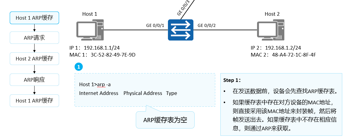
Network devices generally have an ARP cache (ARP Cache). The ARP cache is used to store the association information between IP addresses and MAC addresses.
Before sending data, the device will first search the ARP cache table. If there is an ARP entry of the opposite device in the cache table, the MAC address in the entry is directly used to encapsulate the frame, and then the frame is sent out. If the corresponding information does not exist in the cache table, it is obtained by sending an ARP Request message.
The learned mapping relationship between IP addresses and MAC addresses will be stored in the ARP cache table for a period of time. During the validity period (default: 180s), the device can directly look up the destination MAC address from this table for data encapsulation without ARP query. After this validity period, the ARP entry will be automatically deleted.
If the destination device is on another network, the source device looks up the gateway's MAC address in the ARP cache table. Then send the data to the gateway. Finally, the gateway forwards the data to the destination device.
How ARP Works (2)
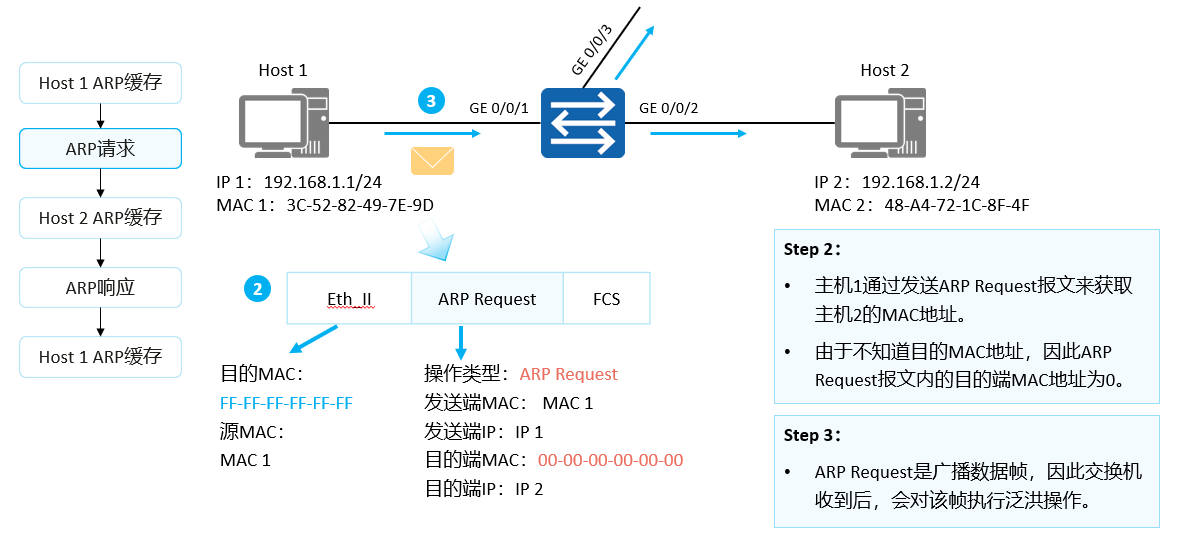
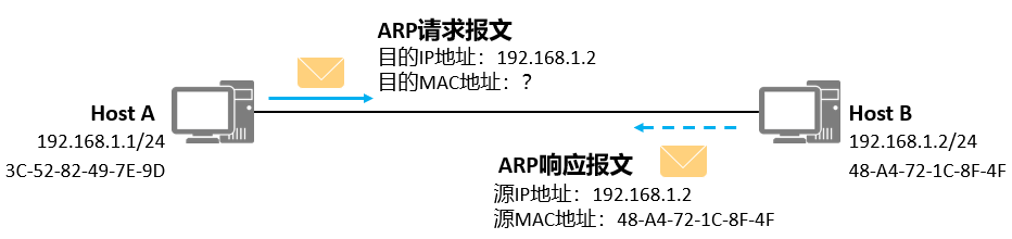
The MAC address of host 2 does not exist in the ARP cache table of host 1, so host 1 sends an ARP Request to obtain the destination MAC address.
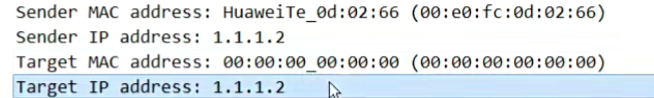
ARP Request messages are encapsulated in Ethernet frames. The source MAC address in the frame header is the MAC address of the sending host 1. At this time, since the host 1 does not know the MAC address of the host 2, the destination MAC address is the broadcast address FF-FF-FF-FF-FF-FF.
The ARP Request message includes the MAC address of the sender, the IP address of the sender, the MAC address of the destination, and the IP address of the destination, where the value of the MAC address of the destination is 0. The ARP Request message will spread throughout the network, and all hosts in the network including the gateway will receive the ARP Request message.
How ARP works (3)
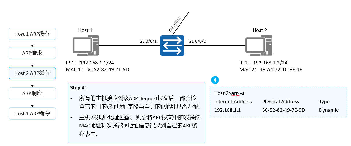
After receiving the ARP Request message, all hosts will check whether the destination IP address field matches its own IP address. If they do not match, the host will not respond to the ARP Request message. If they match, the host will record the sender's MAC address and sender's IP address information in the ARP Request message into its own ARP cache table, and then respond with an ARP Reply message.
How ARP Works (4)
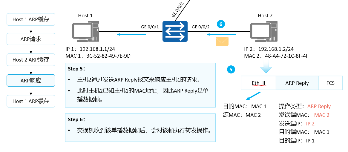
Host 2 responds with an ARP Reply packet to Host 1.
The IP address of the sender in the ARP Reply message is the IP address of host 2, the IP address of the destination is the IP address of host 1, the MAC address of the destination is the MAC address of host 1, and the MAC address of the sender is its own MAC address. At the same time the operation type is set to Reply.
ARP Reply packets are transmitted through unicast.
How ARP Works (5)
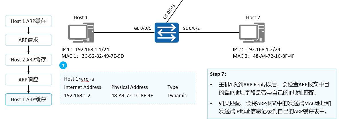
After receiving the ARP Reply, host 1 checks whether the destination IP address field in the ARP packet matches its own IP address. If they match, the sender MAC address and sender IP address in the ARP packet will be recorded in the ARP cache table of host 1.
ICMP
- Internet Control Message Protocol
- ICMP is used to transmit error, control, query and other information
- It is responsible for telling the source host why the network is broken and why the network is unreachable
- Work based on IP, IP is encapsulated in front of ICMP, and Ethernet is encapsulated in front of IP
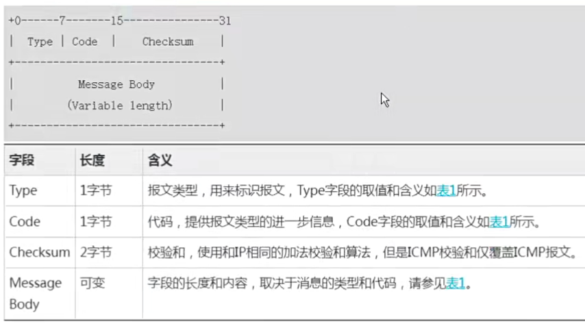
- ICMP is one of the core protocols of the TCP/IP protocol suite. It is used to send control messages between IP network devices, and to transmit information such as errors, control, and queries.
- Consists of Type and Code
- The type and code of ping send 80, and the response is 00
ICMP error detection
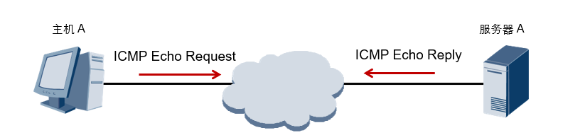
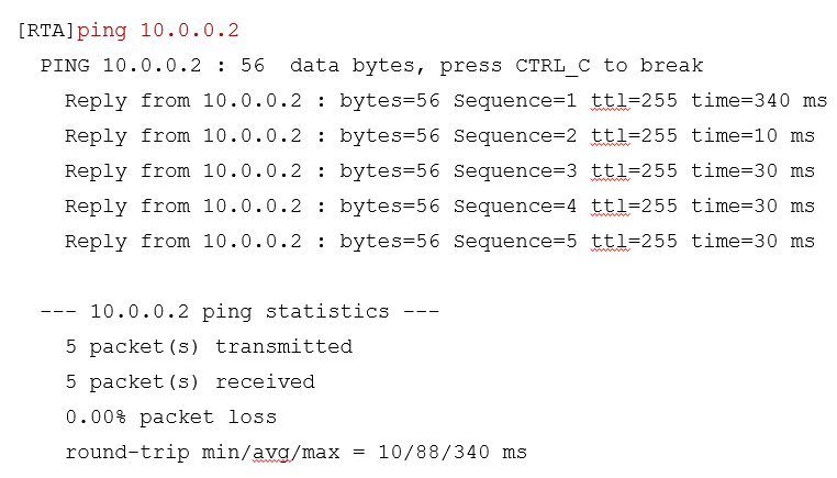
- ICMP Echo Request and ICMP Echo Reply are used to inquire and respond to certain messages respectively for error detection.
- ICMP Echo messages are often used to diagnose the network connectivity between the source and destination, and can also provide other information, such as the round-trip time of packets.
- will send three different port numbers
ICMP Error Reporting
- When the network device cannot access the target, it will automatically send an ICMP destination unreachable message to the sending device.
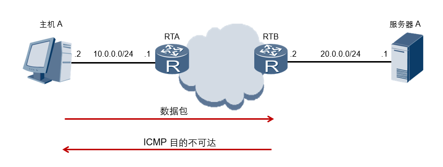
ICMP defines various error messages for diagnosing network connectivity problems; from these error messages, the source device can determine the cause of data transmission failure. For example, if a loop occurs in the network, causing packets to circulate in the network, and eventually the TTL times out, the network device will send a TTL timeout message to the sending device in this case. For another example, if the destination is unreachable, the intermediate network device will send a destination unreachable message to the sending end device. There are many situations where the destination is unreachable. If the network device cannot find the destination network, it will send a destination network unreachable message; if the network device cannot find the destination host in the destination network, it will send a destination host unreachable message.
ICMP Application-Ping
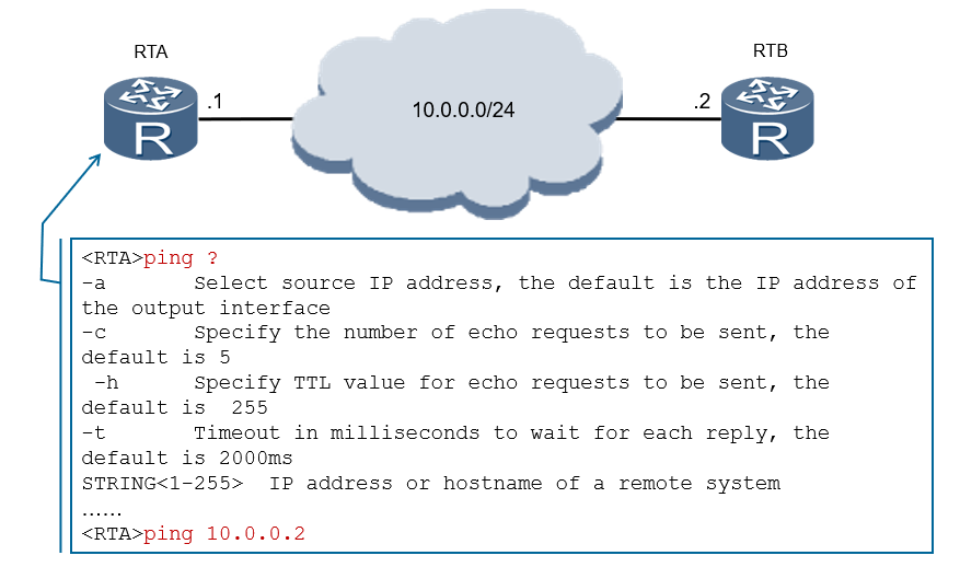
A typical application of ICMP is Ping. Ping is a common tool to detect network connectivity, but also to collect other relevant information. The user can specify different parameters in the Ping command, such as the length of the ICMP packet, the number of ICMP packets to be sent, and the timeout time for waiting for a reply. The device constructs and sends ICMP packets according to the configured parameters to perform the Ping test.
The common configuration parameters of Ping are described as follows:
- -a source-ip-address Specifies the source IP address for sending ICMP ECHO-REQUEST packets. If no source IP address is specified, the IP address of the outgoing interface will be used as the source address of the ICMP ECHO-REQUEST message.
- -c count specifies the number of times to send ICMP ECHO-REQUEST packets. By default, five ICMP ECHO-REQUEST packets are sent.
- -h ttl-value specifies the value of TTL. The default value is 255.
- -t timeout specifies the timeout time for waiting for ICMP ECHO-REPLY after sending ICMP ECHO-REQUEST.
Tracert
- Check at which node the network is disconnected, or check which path the network takes
- Synthesized by ICMP TTL timeout message and UDP port unreachable message
- Tracert shows every hop a packet takes as it travels through the network.
Tracerty application - Tracert
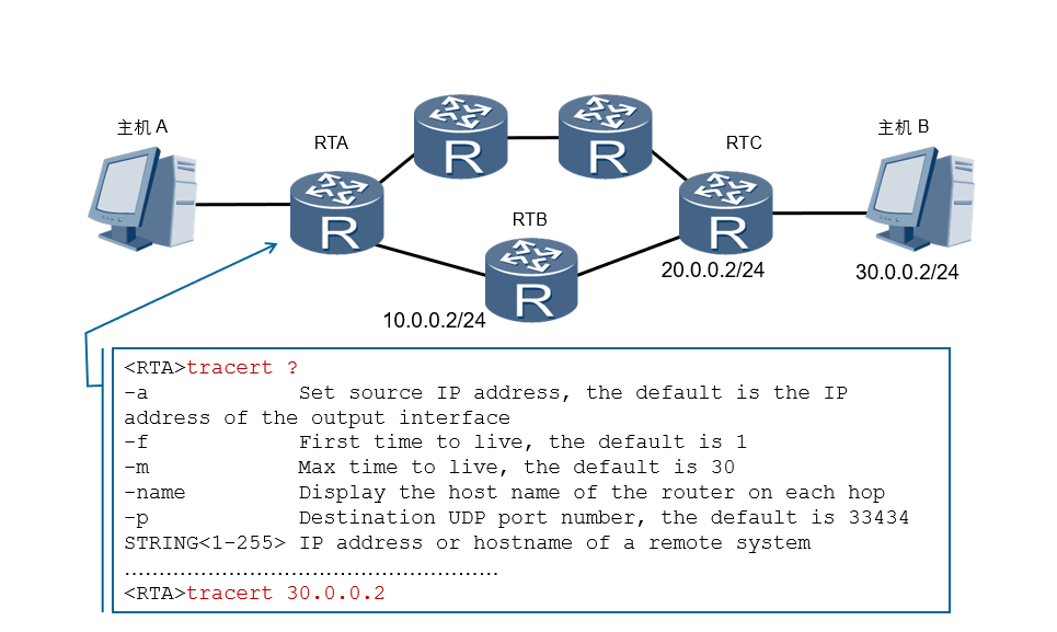
Another typical application of ICMP is Tracert. Tracert traces the forwarding path of packets hop by hop based on the TTL value in the packet header. In order to trace the path to a specific destination address, the source first sets the TTL value of the packet to 1. After the message reaches the first node, the TTL expires, so the node sends a TTL timeout message to the source, and the message carries a timestamp. Then the source end sets the TTL value of the message to 2, and when the message reaches the second node, it times out, and the node also returns a TTL timeout message, and so on, until the message reaches the destination. In this way, the source end can track each node that the message passes through according to the information in the returned message, and calculate the round-trip time according to the timestamp information. Tracert is an effective means to detect network packet loss and delay, and can help administrators discover routing loops in the network.
• The common configuration parameters of Tracert are described as follows:
1. -a source- ip -address specifies the source address of the tracert packet.
2. -f first- ttl specifies the initial TTL. The default value is 1.
3. -m max - ttl specifies the maximum TTL. The default value is 30.
4. -name enables to display the hostname of each hop.
5.-p port specifies the UDP port number of the destination host.
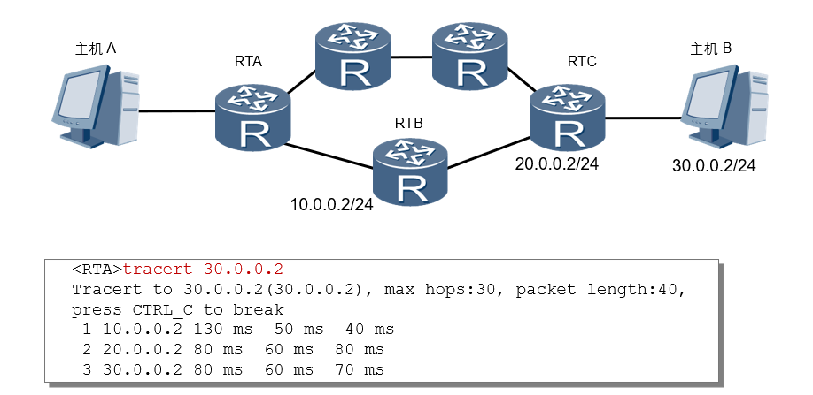
The source (RTA) sends a UDP message to the destination (host B), the TTL value is 1, and the destination UDP port number is a number greater than 30000, because in most cases, any UDP port number greater than 30000 is A port number that is unlikely to be used by any application.
After the first hop (RTB) receives the UDP packet sent by the source, it judges that the destination IP address of the packet is not the local IP address. After decrementing the TTL value by 1, it determines that the TTL value is equal to 0, then discards the packet and Send an ICMP Time Exceeded (Time Exceeded) message to the source (the message contains the IP address of the first hop 10.0.0.2), so that the source gets the address of the RTB.
After receiving the RTB ICMP timeout message, the source sends a UDP message to the destination again with a TTL value of 2.
After the second hop (RTC) receives the UDP message sent by the source, it responds with an ICMP timeout message, so that the source gets the address of RTC (20.0.0.2).
The above process continues until the destination end receives the UDP message sent by the source end and judges that the destination IP address is the local IP address, then processes the message. Find the upper-layer protocol that occupies this port number according to the destination UDP port number in the message, and return an ICMP port unreachable (Destination Unreachable) message to the source end because there is no application program using the UDP port number at the destination end.
After the source end receives the ICMP port unreachable message, it judges that the UDP message has reached the destination end, and then stops the Tracert program, so as to obtain the path (10.0.0.2; 20.0.0.2 ;30.0.0.2).
Gratuitous ARP
- When the ip is configured, send an arp to check whether there is an arp conflict