Article directory
1. Introduction to ESP8266
ESP8266 is a commonly used module in embedded and IoT development, it can be used alone as an MCU, or as a simple WIFI module. ESP8266 can use the serial port to communicate with the microcontroller. ESP8266 can be used to access some APIs, obtain weather information or complete network time service, and can also be connected to the cloud platform for development.
2. Burn the firmware library
Some newly purchased ESP01-S cannot support AT commands, and we need to manually burn the firmware library. Although there are many tutorials for burning the firmware library, the blogger has burned it twice, and the process is not particularly smooth. Here is a special arrangement of the burning steps, which is also convenient for subsequent use. You can contact the seller for the firmware library and burning software, so I won’t put the link here.
First connect the pins according to the table below
| pin | connect |
|---|---|
| 3.3V | 3.3V |
| RST | 3.3V |
| IN | 3.3V |
| IO2 | 3.3V |
| GND | GND |
| 100 | GND |
| TXD | RXD |
| RXD | TXD |
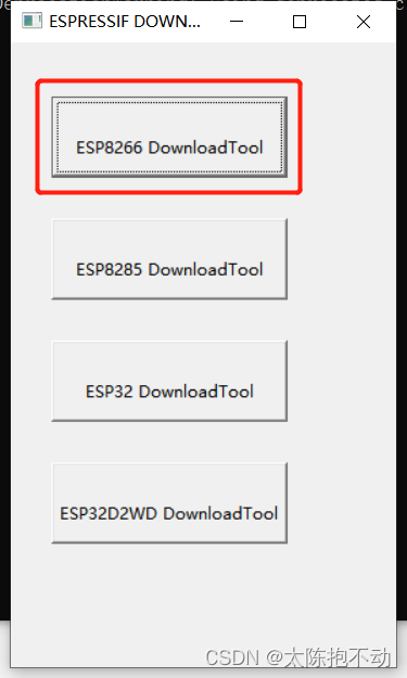
Open the programming software and select ESP8266
Configure as shown below
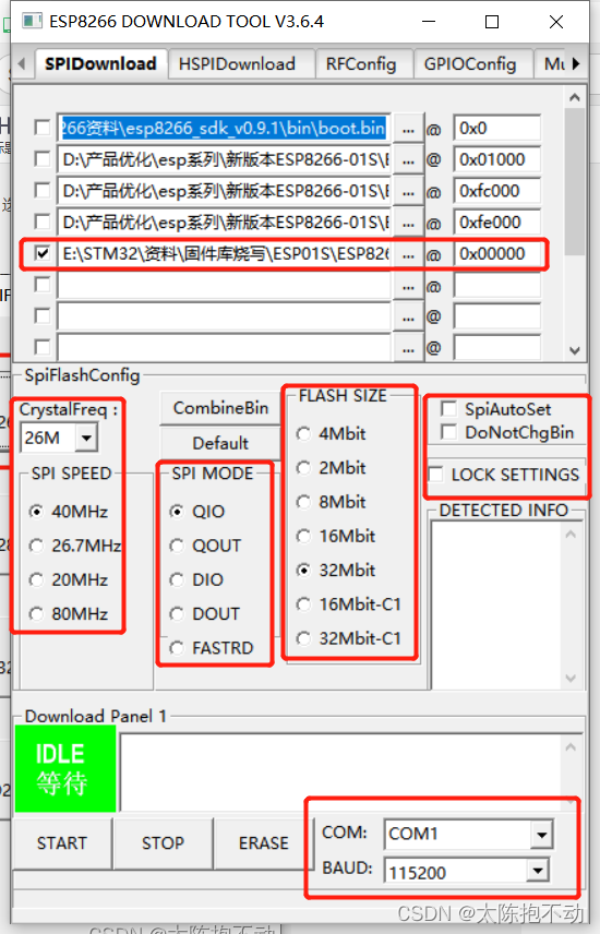
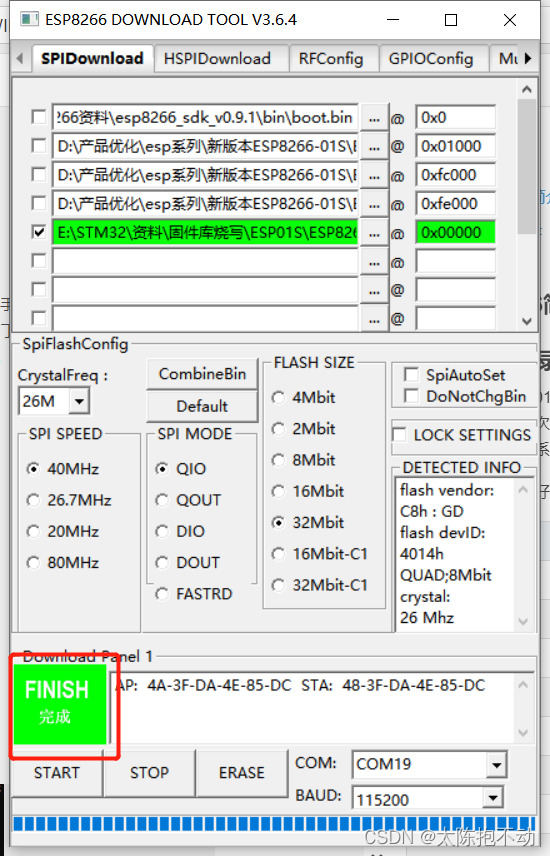
Select the serial port, click "START", and close it after the programming is completed.
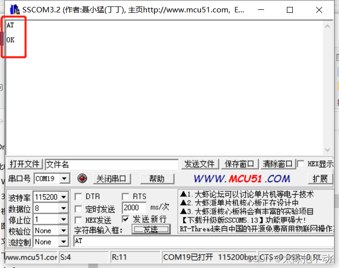
At this point, 拔掉IO0的接地,重新上电。open the serial port debugging assistant to check the burning situation. Open the serial port debugging assistant, send "AT", line feed and enter, and observe the returned information. If it returns "OK", it means the programming is successful.
3. Commonly used AT commands
The following is a brief introduction to some AT commands commonly used in WIFI modules
- AT\r\nCheck
whether the connection of ESP8266 module is normal - AT+CWMODE=1\r\
nConfigure the module as Sta mode - AT+CWJAP="WIFI name", "WIFI password"\r\nConnect
to specified WIFI - AT+CIPMUX=0\r\
nSet to single connection - AT+CIPMODE=1\r\
nOpen transparent transmission mode - AT+CIPSTART=“TCP”,“203.119.175.194”,80\r\
nCreate a TCP connection
How to obtain the IP address will be introduced later - AT+CIPMODE=1\r\
nEnter the transparent transmission mode.
After entering the transparent transmission mode, the AT command will be invalid and needs to be exited to take effect - AT+CIPSEND\r\nPrepare
to send a request to the server. If all the previous commands are successful, a > will appear after sending this command. At this time, just enter the GET information.
4. Access API
Let's take the access to the Xinzhiweath API as an example to introduce the process of using the WIFI module to access the API. Some introductions about the Mind Knowing Weather API will not be repeated here. Before starting the following operations, you need to configure the WIFI module according to the sequence of AT commands described above.
4.1 Get IP address
Computer win+R, input ping api.seniverse.com, click OK to get the IP.
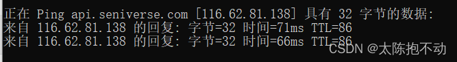
Among them, "116.62.81.138" is the IP address.
4.2 GET weather information
Follow the input sequence of commonly used AT commands in the third section, connect to WIFI, and establish a TCP connection. Finally get the weather information. When getting weather information, enter the following
GET https://api.seniverse.com/v3/weather/now.json?key=你的密钥&location=beijing&language=zh-Hans&unit=c
4.3 Access result display
Use USB to TTL to connect to the WIFI module, and use the serial port debugging assistant to send AT commands to complete the access to the Xinzhiweather API. The result is as follows
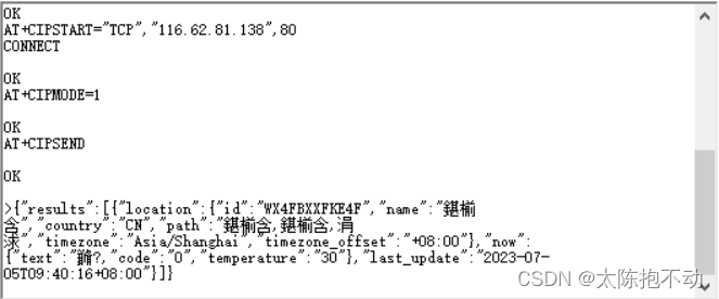
It can be seen that although some are garbled codes, the weather phenomenon code and temperature can be received. About the weather phenomenon code, it is introduced in the API document of knowing the weather
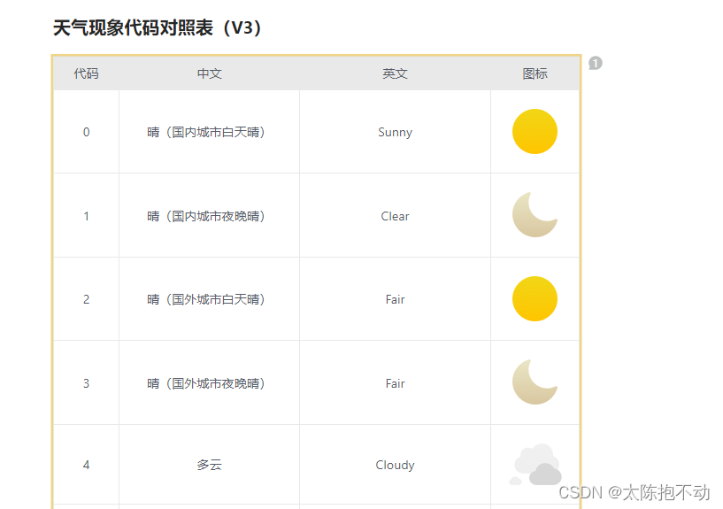
There are many more behind, so I won’t list them here, you can go to the documentation for details.
5. Practical projects
Let's use the WIFI module, with STM32, to access the weather and weather API to obtain the weather and temperature as an example, to show the WIFI program design, for reference only. The project has the following functions
- Serial port 1 communicates with the WIFI module, and can detect whether the WIFI connection is normal
- Use the WIFI module to access the Zhizhiweather API, and use the serial port 2 to print the acquired weather and temperature to the computer
5.1 Serial port configuration
Two serial ports are needed here. 关于串口通信的相关内容这里就不再赘述了,详细可见博主的STM32速成笔记专栏串口通信篇. The serial port initialization procedure is as follows
/*
 *==============================================================================
 *函数名称:uart_init
 *函数功能:初始化USART
 *输入参数:UARTx:串口几;bound:波特率
 *返回值:无
 *备  注:可以修改成输入初始化哪个USART
 *==============================================================================
 */
void uart_init(UART_TypeDef UARTx,u32 bound)
{


	// 相关结构体定义
	GPIO_InitTypeDef GPIO_InitStructure;
	USART_InitTypeDef USART_InitStructure;
	NVIC_InitTypeDef NVIC_InitStructure;

	switch (UARTx)
	{


		case 0:
			// 使能USART1,GPIOA时钟
			RCC_APB2PeriphClockCmd (RCC_APB2Periph_USART1 | RCC_APB2Periph_GPIOA, ENABLE);

			// USART1_TX   GPIOA.9
			GPIO_InitStructure.GPIO_Pin = GPIO_Pin_9;   // PA.9
			GPIO_InitStructure.GPIO_Speed = GPIO_Speed_50MHz;
			GPIO_InitStructure.GPIO_Mode = GPIO_Mode_AF_PP;   // 复用推挽输出
			GPIO_Init(GPIOA, &GPIO_InitStructure);   // 初始化GPIOA.9

			// USART1_RX	  GPIOA.10初始化
			GPIO_InitStructure.GPIO_Pin = GPIO_Pin_10;   // PA10
			GPIO_InitStructure.GPIO_Mode = GPIO_Mode_IN_FLOATING;   // 浮空输入
			GPIO_Init(GPIOA, &GPIO_InitStructure);   // 初始化GPIOA.10

			// Usart1 NVIC 配置
			NVIC_InitStructure.NVIC_IRQChannel = USART1_IRQn;
			NVIC_InitStructure.NVIC_IRQChannelPreemptionPriority=3 ;   // 抢占优先级3
			NVIC_InitStructure.NVIC_IRQChannelSubPriority = 3;   // 子优先级3
			NVIC_InitStructure.NVIC_IRQChannelCmd = ENABLE;   // IRQ通道使能
			NVIC_Init(&NVIC_InitStructure);   // 根据指定的参数初始化VIC寄存器

			// USART 初始化设置
			USART_InitStructure.USART_BaudRate = bound;   // 串口波特率
			USART_InitStructure.USART_WordLength = USART_WordLength_8b;   // 字长为8位数据格式
			USART_InitStructure.USART_StopBits = USART_StopBits_1;   // 一个停止位
			USART_InitStructure.USART_Parity = USART_Parity_No;   // 无奇偶校验位
			// 无硬件数据流控制
			USART_InitStructure.USART_HardwareFlowControl = USART_HardwareFlowControl_None;
			USART_InitStructure.USART_Mode = USART_Mode_Rx | USART_Mode_Tx;   // 收发模式
			USART_Init(USART1, &USART_InitStructure);   // 初始化串口1

			USART_ITConfig(USART1, USART_IT_RXNE, ENABLE);   // 开启串口接收中断
			USART_ITConfig(USART1, USART_IT_IDLE, ENABLE);   // 使能空闲中断

			USART_Cmd(USART1, ENABLE);   // 使能串口1

			break;

		case 1:
			// 使能USART2,GPIOA时钟
			RCC_APB1PeriphClockCmd (RCC_APB1Periph_USART2 | RCC_APB2Periph_GPIOA, ENABLE);

			// USART2_TX   GPIOA.2
			GPIO_InitStructure.GPIO_Pin = GPIO_Pin_2;   // PA.2
			GPIO_InitStructure.GPIO_Speed = GPIO_Speed_50MHz;
			GPIO_InitStructure.GPIO_Mode = GPIO_Mode_AF_PP;   // 复用推挽输出
			GPIO_Init(GPIOA, &GPIO_InitStructure);   // 初始化GPIOA.2

			// USART2_RX	  GPIOA.3初始化
			GPIO_InitStructure.GPIO_Pin = GPIO_Pin_3;   // PA3
			GPIO_InitStructure.GPIO_Mode = GPIO_Mode_IN_FLOATING;   // 浮空输入
			GPIO_Init(GPIOA, &GPIO_InitStructure);   // 初始化GPIOA.3

			// Usart2 NVIC 配置
			NVIC_InitStructure.NVIC_IRQChannel = USART2_IRQn;
			NVIC_InitStructure.NVIC_IRQChannelPreemptionPriority=3 ;   // 抢占优先级3
			NVIC_InitStructure.NVIC_IRQChannelSubPriority = 3;   // 子优先级3
			NVIC_InitStructure.NVIC_IRQChannelCmd = ENABLE;   // IRQ通道使能
			NVIC_Init(&NVIC_InitStructure);   // 根据指定的参数初始化VIC寄存器

			// USART2 初始化设置
			USART_InitStructure.USART_BaudRate = bound;   // 串口波特率
			USART_InitStructure.USART_WordLength = USART_WordLength_8b;   // 字长为8位数据格式
			USART_InitStructure.USART_StopBits = USART_StopBits_1;   // 一个停止位
			USART_InitStructure.USART_Parity = USART_Parity_No;   // 无奇偶校验位
			// 无硬件数据流控制
			USART_InitStructure.USART_HardwareFlowControl = USART_HardwareFlowControl_None;
			USART_InitStructure.USART_Mode = USART_Mode_Rx | USART_Mode_Tx;   // 收发模式
			USART_Init(USART2, &USART_InitStructure);   // 初始化串口2

			USART_ITConfig(USART2, USART_IT_RXNE, ENABLE);   // 开启串口接收中断
			USART_ITConfig(USART2, USART_IT_IDLE, ENABLE);   // 使能空闲中断

			USART_Cmd(USART2, ENABLE);   // 使能串口2

			break;

			default:
				break;
	}
}
值得注意的是,串口2挂载在APB2上,开启串口2时钟时需要注意。The blogger initially used the wrong function to turn on the clock, causing the PA2 pin to output a low level all the time.
printf is used for the output of serial port 1, and another serial port sending function needs to be defined
/*
 *==============================================================================
 *函数名称:USART_Send
 *函数功能:串口发送函数
 *输入参数:str:要发送的数据的数组首地址;UARTx:串口几
 *返回值:无
 *备  注:调用前先将需要发送的内容利用sprintf()函数转换成字符串,再进行发送
 *==============================================================================
 */
void USART_Send (UART_TypeDef UARTx,u8 *str)
{


	u8 index = 0;

	do
	{


		switch (UARTx)
		{


			case 0:
				USART_SendData(USART1,str[index ++]);
				while (USART_GetFlagStatus(USART1,USART_FLAG_TXE) == RESET);
				break;

			case 1:
				USART_SendData(USART2,str[index ++]);
				while (USART_GetFlagStatus(USART2,USART_FLAG_TXE) == RESET);
			break;
		}
	}
	while(str[index] != 0);
}
5.2 Detect WIFI module connection status
The detection principle is very simple, just use the serial port 1 to send "AT\r\n" to the WIFI module, and check whether "OK" is received. If "OK" is received, the connection is normal. If "OK" is not received, the connection is abnormal. Use serial port 2 to output the connection status. The serial port 1 sends "AT" to the WIFI module. The program is as follows
u8 gOkFlag = 0;   // 配置成功标志位

/*
 *==============================================================================
 *函数名称:Med_Esp8266_CheckLink
 *函数功能:检查ESP8266连接状态
 *输入参数:无
 *返回值:0:未连接;1:连接正常
 *备  注:一直发送AT,直到接收到OK
 *==============================================================================
 */
u8 Med_Esp8266_CheckLink (void)
{


	while (!gOkFlag)
	{


		// 发送AT,检查连接状态
		printf ("AT\r\n");
		delay_ms(100);

		return 0;
	}

	gOkFlag = 0;   // 清零配置成功变量
	return 1;
}
Keep sending in a loop until "OK" is detected in the returned content. The receiving interrupt function and analysis function of serial port 1 are as follows
/*
 *==============================================================================
 *函数名称:USART1_IRQHandler
 *函数功能:USART1中断服务函数
 *输入参数:无
 *返回值:无
 *备  注:无
 *==============================================================================
 */
u32 gReceCount = 0;   // 接收计数变量
u32 gClearCount = 0;   // 清空接收数组计数变量
u8 gReceFifo[1500];   // 接收数组
u8 gReceEndFlag = 0;   // 接收完成标志位

void USART1_IRQHandler(void)
{


	if(USART_GetITStatus(USART1, USART_IT_RXNE) != RESET)   //接收到一个字节
	{


		gReceFifo[gReceCount++] = USART_ReceiveData(USART1);
	}
	else if(USART_GetITStatus(USART1,USART_IT_IDLE) != RESET)   //接收到一帧数据
	{


		USART1->SR;   // 先读SR
		USART1->DR;   // 再读DR

		gReceEndFlag = 1;   // 接收完成标志置1
	}
}
/*
 *==============================================================================
 *函数名称:Uart_Rece_Pares
 *函数功能:解析串口接收内容
 *输入参数:无
 *返回值:无
 *备  注:无
 *==============================================================================
 */
extern u8 gOkFlag;   // 配置成功标志位

void Uart_Rece_Pares(void)   // 串口接收内容解析函数
{


	u16 tempVar = 0;   // 临时循环变量

	if (gReceEndFlag  == 1)   // 如果接收完成
	{


		// 解析接收内容
		for (tempVar = 0;tempVar < gReceCount;tempVar ++)
		{


			if (gReceFifo[tempVar] == 'O' && gReceFifo[tempVar + 1] == 'K')
			{


				gOkFlag = 1;   // 成功标志位置1
				break;
			}
		}

		// 清空接收数组
		for (gClearCount = 0;gClearCount < gReceCount;gClearCount ++)
		{


			gReceFifo[gClearCount] = ' ';
		}

		gReceEndFlag = 0;   // 清除接收完成标志位
		gReceCount = 0;   // 清零接收计数变量
	}
}
After power on, check the connection status of the WIFI module, and the serial port 2 returns information
	u32 checkCunt = 0;   // 检测连接状态计次变量

	Med_Mcu_Iint();   // 系统初始化

	// 检查ESP8266模块连接状态
	while (!Med_Esp8266_CheckLink())
	{


		checkCunt = checkCunt + 1;   // 检测计数变量加1

		// 检测接收内容
		Uart_Rece_Pares();

		// 未连接
		if (checkCunt > 1)
		{


			sprintf((char*)gString,"ESP8266未连接!\r\n");
			USART_Send(UART2,gString);
			delay_ms(500);
		}
	}
	sprintf((char*)gString,"ESP8266已连接!\r\n");
	USART_Send(UART2,gString);
5.3 Send configuration command
Here is a function to send configuration commands, serial port 1 sends commands to the WIFI module, and serial port 2 observes whether the sending is successful.
/*
 *==============================================================================
 *函数名称:Med_Esp8266_CheckLink
 *函数功能:检查ESP8266连接状态
 *输入参数:str:要发送的指令
 *返回值:无
 *备  注:调用前先将需要发送的内容利用sprintf()函数转换成字符串
					串口1发送指令,串口2返回信息
 *==============================================================================
 */
u8 gSendCunt = 0;   // 记录发送次数

void Med_Esp8266_SendCmd (u8 *str)
{


	u8 string[100];

	while (!gOkFlag)
	{


		// 发送AT指令
		USART_Send(UART1,str);
		delay_ms(1000);

		gSendCunt = gSendCunt + 1;   // 发送次数加1

		// 检测接收内容
		Uart_Rece_Pares();

		if (gSendCunt > 10)
		{


			sprintf((char*)string,"%s指令发送失败!\r\n",str);
			USART_Send(UART2,string);
		}
	}

	sprintf((char*)string,"%s指令发送成功!\r\n",str);
	USART_Send(UART2,string);
	gSendCunt = 0;   // 清零发送次数
	gOkFlag = 0;   // 清零配置成功变量
}
The configuration steps are as follows
	// 配置模块为Sta模式
	sprintf((char*)gString,"AT+CWMODE=1\r\n");
	Med_Esp8266_SendCmd(gString);

	// 连接指定WIFI
	sprintf((char*)gString,"AT+CWJAP=\"ertu\",\"ertu201801101102\"\r\n");
	Med_Esp8266_SendCmd(gString);

	// 设置成单连接
	sprintf((char*)gString,"AT+CIPMUX=0\r\n");
	Med_Esp8266_SendCmd(gString);

	// 开启透传模式
	sprintf((char*)gString,"AT+CIPMODE=1\r\n");
	Med_Esp8266_SendCmd(gString);

	// 创建TCP连接
	sprintf((char*)gString,"AT+CIPSTART=\"TCP\",\"116.62.81.138\",80\r\n");
	Med_Esp8266_SendCmd(gString);

	// 进入透传模式
	sprintf((char*)gString,"AT+CIPMODE=1\r\n");
	Med_Esp8266_SendCmd(gString);

	// 准备向服务器发送请求
	sprintf((char*)gString,"AT+CIPSEND\r\n");
	Med_Esp8266_SendCmd(gString);
5.4 Parsing weather information
The next step is to request weather information from the server and then parse it. It is necessary to modify the analysis function of the content received by the serial port. When the "code" is received, the weather information is considered successful, and the weather information is parsed and returned.
/*
 *==============================================================================
 *函数名称:Uart_Rece_Pares
 *函数功能:解析串口接收内容
 *输入参数:无
 *返回值:无
 *备  注:无
 *==============================================================================
 */
extern u8 gOkFlag;   // 配置成功标志位

void Uart_Rece_Pares(void)   // 串口接收内容解析函数
{


	u16 tempVar = 0;   // 临时循环变量
	u8 string[100];   // 串口打印数组

	if (gReceEndFlag  == 1)   // 如果接收完成
	{


		// 解析接收内容
		for (tempVar = 0;tempVar < gReceCount;tempVar ++)
		{


			if (gReceFifo[tempVar] == 'O' && gReceFifo[tempVar + 1] == 'K')
			{


				gOkFlag = 1;   // 成功标志位置1
				break;
			}

			// 接收到API返回结果
			// 针对心知天气API
			if (gReceFifo[tempVar] == 'c' && gReceFifo[tempVar + 1] == 'o' && gReceFifo[tempVar + 2] == 'd'
					 && gReceFifo[tempVar + 3] == 'e')
			{


				sprintf((char*)string,"天气信息获取成功\r\n");
				USART_Send(UART2,string);

				// 提取天气信息
				sprintf((char*)string,"天气现象代码:%c   温度:%c%c℃\r\n",gReceFifo[tempVar + 7],gReceFifo[tempVar + 25]
																																													,gReceFifo[tempVar + 26]);
				USART_Send(UART2,string);
				break;
			}
		}

		// 清空接收数组
		for (gClearCount = 0;gClearCount < gReceCount;gClearCount ++)
		{


			gReceFifo[gClearCount] = ' ';
		}

		gReceEndFlag = 0;   // 清除接收完成标志位
		gReceCount = 0;   // 清零接收计数变量
	}
}
6. Results display

In summary, the blogger is quite satisfied with the command sending function of ESP8266, but due to the limited ability of the blogger, these are for reference only.