A common feature used in almost every embedded application is the ADC module (Analog to Digital Converter). These ADCs can read voltages from analog sensors like temperature sensors, tilt sensors, current sensors, bend sensors, etc. Now, we learn how to use the ADC in STM32F103C8 to read the analog voltage. We connect a potentiometer to the STM32 Blue Pill board, change the resistance of the potentiometer to provide different voltages for the ADC, and display the read voltage on the 1602 LCD .
ADC in STM32F103C8
There are 10 channels, 12-bit ADC in STM32F103C8, and the input range is 0V -3.3V. It maps an input voltage between 0 and 3.3 volts to an integer value between 0 and 4095.
The term 10 channels here means that there are 10 ADC pins available for measuring analog voltages. The term 12 bits means the resolution of the ADC, which means 000000000000-111111111111 (2^12 is 4096). This is the number of sampling steps for our ADC, so our ADC values range from 0 to 4095. The value will increase from 0 to 4095 based on the voltage value per step, which can be calculated by aspect
Voltage / Steps = Reference Voltage / 4096 = (3.3/4096= 8.056mV) per unit.
How Analog Signals Are Converted to Digital Format
Since computers only store and process binary/digital values (1 and 0). Therefore, an analog signal, such as a sensor's volt output, must be converted to a digital value for processing, and the conversion needs to be accurate. When an input analog voltage is provided to the STM32 at an analog input, the analog value is read and stored in an integer variable. Convert the stored analog value (0-3.3V) to an integer value (0-4096) using:
Input voltage = (ADC value / ADC resolution) * reference voltage
resolution = 4096
Reference voltage = 3.3V
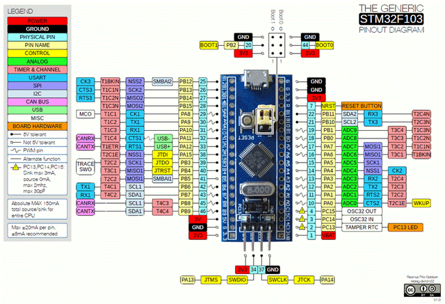
ADC pins in STM32F103C8T6
There are 10 ADC pins in STM32, from PA0 to PB1.
Circuit Diagram and Description

LCD and STM32 connection

The 1602 LCD is connected according to the table above. There are two potentiometers in the circuit, the first one is used as a voltage divider to change the voltage and provide an analog input to the STM32. The left pin of this potentiometer gets input positive voltage from STM32 (3.3V), the right pin is grounded, and the center pin of the potentiometer is connected to the analog input pin (PA7) of STM32. Another potentiometer is used to change the contrast of the LCD display. The power supply of STM32 is provided by the USB power supply of PC.

Program STM32 to read ADC value
Connect the STM32 to the PC via its USB port and start programming with the ARDUINO IDE. In the program, read the analog value and use that value to calculate the voltage and then display the analog and digital values on the LCD screen.
#include <LiquidCrystal.h> // LCD 库
//首先 定义出 LCD 引脚。这些定义了 LCD 引脚连接到 STM32 的哪个引脚。
//你可以根据自己的需求进行修改。
const int rs = PB11, en = PB10, d4 = PB0, d5 = PB1, d6 = PC13, d7 = PC14;
LiquidCrystal lcd(rs, en, d4, d5, d6, d7); //初始化LCD
const int analogip = PA7;//模拟输入引脚
void setup()
{
    lcd.begin(16, 2); //我们使用的是 16*2 LCD
    lcd.clear(); //清屏
    lcd.setCursor(0, 0); //设置光标在第一行第一列
    lcd.print("Hello Wrold!"); //LCD显示这个
    lcd.setCursor(0, 1); //设置光标在第二行第一列
    lcd.print("STM32F103C8"); //LCD显示这个
    delay(2000);//等待两秒
    lcd.clear(); //清屏
    lcd.setCursor(0, 0); //设置光标在第一行第一列
    lcd.print("USING ADC IN");//打印这个
    lcd.setCursor(0,1); //设置光标在第二行第一列
    lcd.print("STM32F103C8");//打印这个
    delay(2000); //等待两秒
    lcd.clear(); //清屏
}

void loop()
{
    int val = analogRead(PA7); // 从引脚 A7 读取 ADC 值
    float voltage = (float(val)/4096) * 3.3; //将 ADC 值转换为电压值
    lcd.setCursor(0, 0); // 将光标设置到第 0 列第 0 行
    lcd.print("ADC Val:");
    lcd.print(val); //显示ADC值
    lcd.setCursor(0, 1); // 将光标设置到第 0 列第 1 行
    lcd.print("Voltage:");
    lcd.print(voltage);//显示电压
}
This is the end of this article, mistakes are welcome to point out.