1. Introduction to STP
In order to perform link backup and improve network reliability in an Ethernet switching network, redundant links are usually used. However, the use of redundant links will generate loops on the switching network, causing broadcast storms and unstable MAC address tables, resulting in poor user communication quality and even communication interruption. In order to solve the loop problem in the switching network, the Spanning Tree Protocol (STP) is proposed.
The basic idea of STP is that physical connections can have closed loops, but STP can temporarily "close" some ports to avoid loops. If a link fails, release the "closed" port. In this way, regardless of whether the link fails, there will be no loops, and broadcast storms are avoided.
STP in a broad sense refers to all spanning tree protocols, and STP in a narrow sense refers to the standards defined by 802.1d.
There are many versions of STP. The 802.1d standard defines the earliest version, followed by RSTP (Rapid Spanning Tree Protocol) defined by 802.1w standard and MSTP (Multiple Spanning Tree Protocol) defined by 802.1s. protocol).
2. Basic concepts of STP
- Bridge (Bridge)
Early switches generally only had two forwarding ports, so the switches at that time were often called "bridges", or "bridges" for short. Later, the term "bridge" has been used to this day, but it does not refer to a switch with only two forwarding ports, but generally refers to a switch with any number of ports. Currently the terms "bridge" and "switch" are used interchangeably. - Bridge MAC Address (Bridge MAC Address)
We know that a bridge has multiple forwarding ports, and each port has a MAC address. Usually, we use the MAC address of the port with the smallest port number as the MAC address of the entire bridge. - BID (Bridge Identifier, Bridge ID )
The bridge ID of a bridge (switch) consists of two parts, namely: bridge priority + MAC address of the bridge; the value of the bridge priority can be set manually, and the default value is 0x8000 (equivalent to 32768 in decimal). The value range is 0~65535. - PID (Port Identifier, Port ID )
The port ID of a certain port of a bridge (switch) consists of two parts, namely: port priority + port number; the value of port priority can be set manually. Devices from different manufacturers may have different numbers of bytes occupied by the two parts. - Path Cost
Path Cost (Path Cost) is a port variable, which is a reference value used by the STP protocol for link selection. The STP protocol calculates the path cost, selects a "stronger" link, blocks redundant links, and prunes the network into a loop-free tree network structure. In an STP network, the path cost from a port to the root bridge is the sum of the path costs of the ports on the bridges it passes through. This value is called the root path cost (Root Path Cost).
3. STP election process
First elect the root bridge (Root Bridge), then each non-root switch elects a root port (Root Port, RP) and each link elects a designated port (Designated Port, DP), and finally blocks the standby port (Alternate Port, AP )
1. Election Root Bridge
The election of the root bridge is firstly to compare the Bridge ID. Whoever has the smaller Bridge ID will be selected as the root bridge first.
-
Bridge ID = Priority ( 32768 by default ) + MAC ( MAC address )
-
First compare the priority, if the priority is the same then compare the MAC address
-
The Bridge ID is 8 bytes in total, of which the MAC address occupies 6 bytes, and the Priority occupies 2 bytes.
-
When the switch starts up for the first time, it will assume that it is the root bridge, and it will put its own Bridge ID into the Root Bridge ID and Bridge ID in the BPDU sent out.
-
When it receives a smaller Bridge ID, it writes the ID into the BPDU it sends, and then notifies the updated BPDU to other switches.
-
By continuously exchanging BPDUs and comparing Bridge IDs, the final root bridge will be elected.
-
The root bridge generates Configuration BPDUs and sends them out through available paths every 2 seconds. The remaining switches cannot generate BPDUs and can only forward BPDUs sent by the root bridge (the bridge ID in the forwarded BPDU packet is the bridge ID of the forwarder).
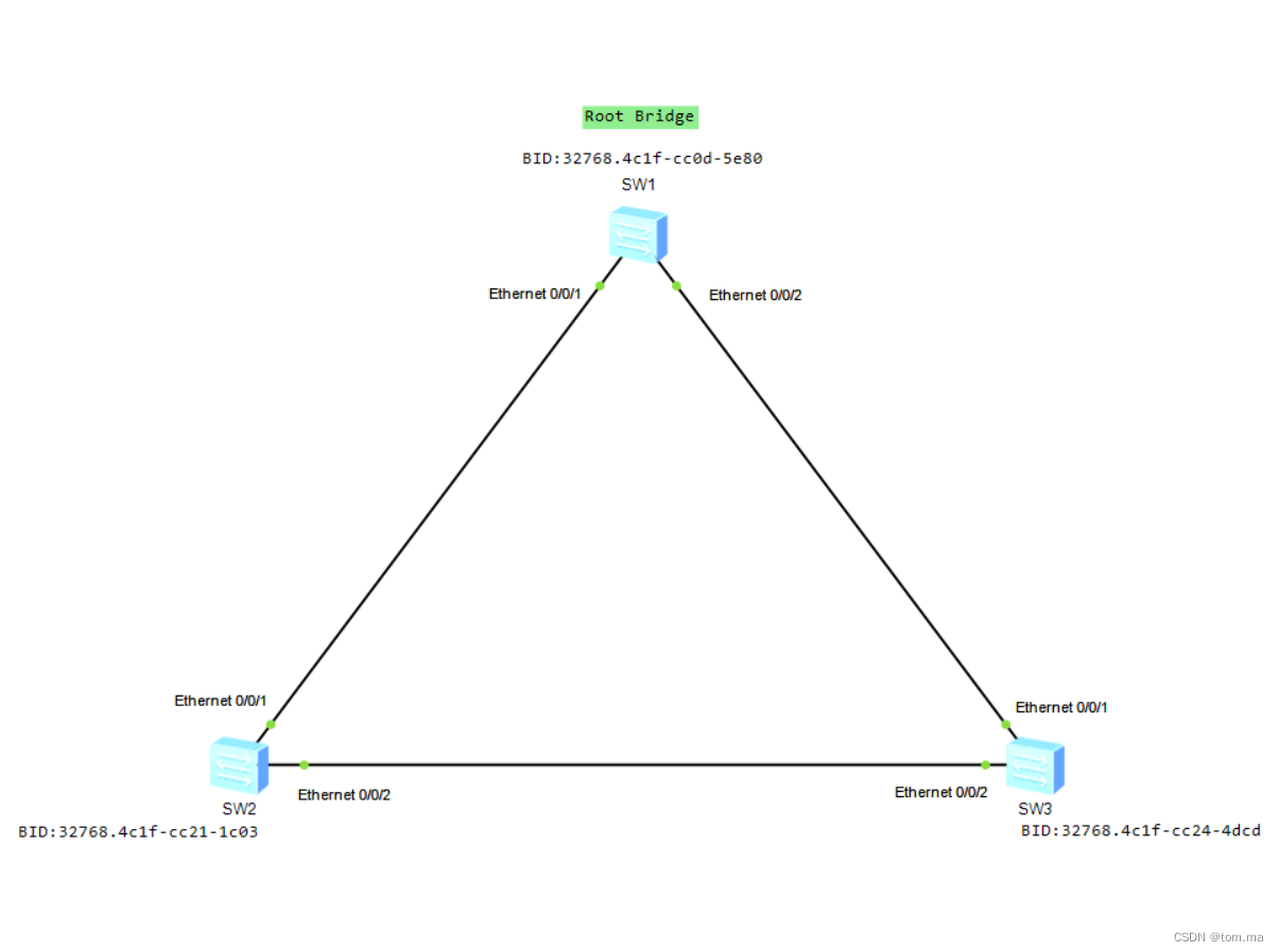 As shown in the figure, switches SW1, SW2, and SW3 all use the default bridge priority of 32768. Obviously SW1 has the smallest BID, so SW1 will be elected as the root bridge in the end.
2. Election root port
After the root bridge is determined, other switches that do not become root bridges are called non-root bridges (or non-root switches). A non-root bridge device may have multiple ports connected to the network. In order to ensure that the working path from a non-root bridge device to the root bridge is optimal and unique, it must be A port to be called the "root port" is determined, and the root port is used as a port for message exchange between the non-root bridge device and the root bridge device. There can be at most one root port on a non-root bridge device .
The non-root bridge elects the root port based on the port's root path cost, peer BID, peer PID, and local PID. In a network running the STP protocol, we call the cumulative path cost from a port of a switch to the root bridge (that is, the sum of the path costs of all links passing from the port to the root bridge) the root path cost of this port ( Root Path Cost, RPC). The path cost of a link is related to the port rate. The higher the port forwarding rate, the smaller the path cost. By default, the calculation method of the path cost is the IEEE 802.1T ( dot1t ) standard method. Below is the change command
[Huawei]stp pathcost-standard ?
  dot1d-1998  IEEE 802.1D-1998
  dot1t       IEEE 802.1T
  legacy      Legacy
The corresponding relationship between port rate and path cost is shown in the following table:
| port speed | Path overhead (802.1D-1998 standard) | Path overhead (IEEE802.1T standard) |
| 100Mbit/s | 19 | 200 000 |
| 1000Mbit/s | 4 | 20 000 |
| 10Gbit/s | 2 | 2 000 |
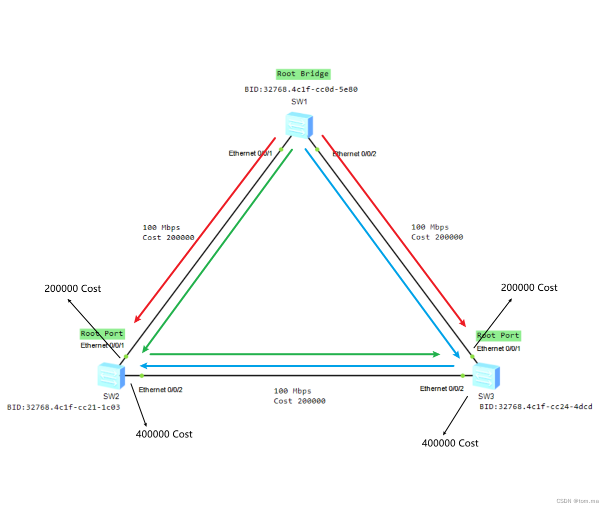
As shown in the figure: port 1 of SW2 and port 1 of SW3 are the root ports, because the path cost from the root bridge to these two ports (direction of the red line) is the smallest, both are 200,000, and the root bridge to port 2 of SW2 (direction of the blue line), The cost of the path from the root bridge to the port 2 of SW3 (in the direction of the green line) is 400,000.
3. Election of designated ports
In order to prevent the existence of working loops, the working path between each network segment and the root bridge in the network must also be unique and optimal. When a network segment has two or more paths leading to the root bridge, the switch connected to the network segment must determine a unique designated port. The designated port is also determined by comparing RPCs, and the port with the smaller RPC will become the designated port. If the RPCs are the same, you need to compare the BID, PID, etc. All ports on the root bridge are designated ports.
The election of the designated port is different from that of the root port: the root port is that all the ports on each switch participate in the election together, and the only one is selected in the internal fighting at home; while the designated port is elected on each physical link One is the election of ports between different connected switches, which is fighting with outsiders.
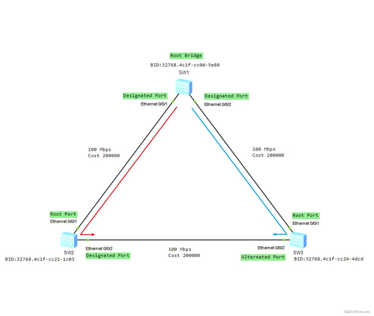
As shown in the figure above, the links SW2 and SW3 can lead to the root bridge from the red (2 ports of SW2) and blue (2 ports of S3) respectively, but the RPC overhead is the same at this time, both are 200,000, and then compare BID, SW2 is smaller than SW3, so the 2 port of SW2 is the designated port.
After the designated ports on each link are selected, STP will block all the remaining ports, which are called blocked ports (AP, Alternate Port), here are the 2 ports of SW3. After the AP port is blocked, it will not send any data, including BPDU. However, in order to keep STP normal, BPDUs sent to it by others are still received, and other data are not received any more and are all discarded. So far, the STP calculation is completed, the loop is eliminated, and the spanning tree converges.
4. STP port status transition
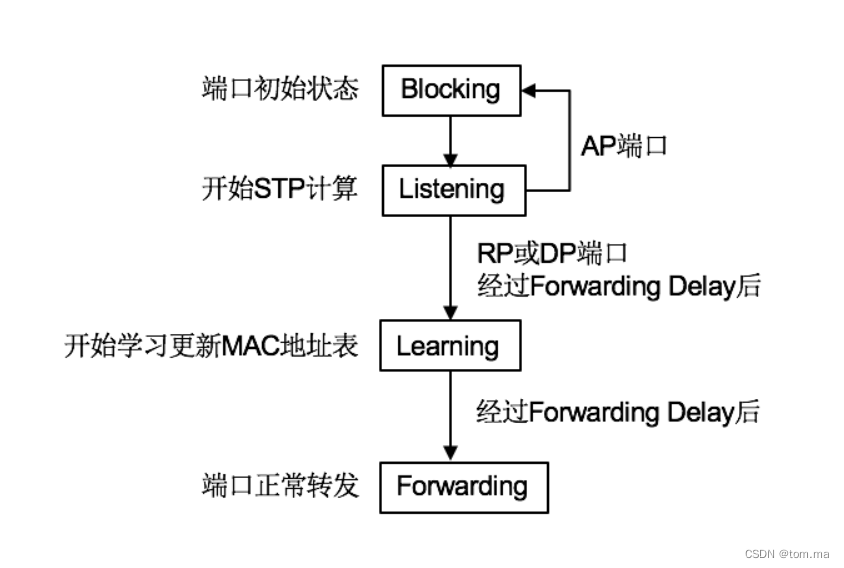
- After STP elects the root bridge and determines the port role, the spanning tree converges and the loop is eliminated. However, the calculation of STP requires a process after all, and it takes a little time. So before the root bridge is selected and the port role is determined, is there still a loop? That's right, there are indeed temporary loops before the spanning tree converges. To avoid temporary loops, STP introduces "port states". STP stipulates that all ports are in the Blocking state in the initial state! What is the Blocking state? A port in this state will only receive BPDUs and do nothing else! It will neither receive any data nor send any message, including BPDU. In this way, there will definitely be no loops: if no one sends anything, how can there be loops.
- Then, with an order from STP, the state of all ports changes from Blocking to Listening. A port in the Listening state can send and receive BPDUs, but does nothing else. Since it can send and receive BPDUs, STP can start to work, elect the root bridge, and determine the root port, designated port and blocked port.
- Selected as the blocked port of AP, STP changes their port state from Listening state to Blocking state immediately. For the ports selected as RP and DP, STP will change their state from Listening state to Learning state after Forwarding Delay time (15 seconds by default).
- The port in the Learning state, like the Listening state, will send and receive BPDUs, and will not forward any other data, but it does one more thing than the Listening state, it will learn the MAC address table, that is, it will receive the port in the message. The source MAC address is written into the MAC address table, or its aging time is updated.
- After the Forwarding Delay time elapses, STP changes the port in the Learning state to the Forwarding state again. The Forwarding state is the final stable state of the port. A port in the Forwarding state will send and receive any data, and will also learn to update the MAC address table, just like a normal port.
- After the port state transition is completed, the port in the Forwarding state starts to send and receive data normally, while the port in the Blocking state is blocked and does not forward any data except for receiving BPDUs, thus eliminating the loop. We noticed that the AP port must be in the Blocking state, and the RP and DP ports must be in the Forwarding state, but the RP and DP ports must be in the Forwarding state, and it takes 2 times the Forwarding Delay time, which is 30 seconds by default before starting to forward data. If no BPDU is received after the Max Age time (20 seconds by default), and the lifetime reaches the maximum lifetime, the bridge considers that the link connected to the interface fails and will re-elect the root bridge.
5. Manually adjust the root bridge and specify the port
1. Adjust the root bridge, the value is 0 or a multiple of 4096
# 调整主根桥
stp priority 0 或者 stp root primary

# 调整备根桥
stp priority 4096 或者 stp root secondary
2. Adjust the designated port
stp cost 210000