Summary
As an important parameter of health, temperature has been paid close attention to for a long time. In the era of epidemics, temperature detection is also an essential part of epidemic prevention and control. Traditional thermometers have shortcomings such as slow response, poor measurement accuracy, long measurement time, and cumbersome temperature measurement process. Therefore, the design and implementation of a human body temperature measurement system based on a single-chip microcomputer is of great significance in the context of the post-epidemic.
In this design, the selection and specifications of the main chip and main components follow the principle of function priority and high cost performance. The system uses the smallest system board of STM32F103, the temperature sensor uses DS18B20, and the liquid crystal display part uses LCD1602 liquid crystal screen. The functions that the system can realize include human body temperature measurement with a measurement accuracy of ±0.1°C, preset human body normal temperature interval values, comparison of detected temperature values, and buzzer alarms.
This design can realize the detection and display of the temperature of the human body. It is easy to use, easy to carry, and fast to detect. It only takes 5 seconds to detect the temperature of the human body, and the error is only ±0.5°C. In the post-epidemic era, the temperature gun designed this time has certain practical value and is of great significance for epidemic prevention and control and human health detection.
Key words
STM32F103; DS18B20; temperature; LCD1602
directory
1.1 Research background and significance
1.2 Analysis of current situation at home and abroad
2.3 Minimum single chip system
2.5 Control buttons and independent buttons
Chapter 1 Introduction
1.1 Research background and significance
Temperature is a basic physical quantity that describes how hot or cold an object is. In people's daily production and life, temperature is an important parameter. The change of temperature can convey extremely important information to people, so the measurement and monitoring of temperature is very meaningful. Some industries have higher requirements on temperature, and a slight change in temperature will have irreparable consequences. For example, food storage in the food industry must ensure that the food is kept in a suitable temperature and humidity; in the management of archives, paper products are extremely sensitive to temperature and humidity, and storage in an unsuitable temperature will seriously reduce the storage life of the archives; in addition, in the medical industry , The physical condition of the patient will also be shown by temperature, especially after the outbreak last year, the detection of temperature has greater significance.
Traditional mercury temperature measurement often takes a long time and is not very convenient to read. This paper designs a human body temperature measurement system based on STM32, which can display the body temperature in real time and judge whether the temperature is abnormal.
1.2 Analysis of current situation at home and abroad
China is a populous country, and the demand for thermometers is huge. Traditional mercury-type thermometers were used a lot before the epidemic. There are about 430 million used in China, basically one for each family. However, mercury thermometers have the disadvantages of being fragile and inconvenient to read, and mercury, a heavy metal, is harmful to human health. Therefore, the reform and innovation of the human body thermometer has important social significance. At the beginning of 2020, the outbreak of the new crown epidemic made doctors and people more impatient for the innovation of thermometers, which promoted the production and use of intelligent human body temperature guns. At present, my country has developed a human body infrared thermometer that is small in size, low in cost, and free from interference from external ambient temperature.
There are also many technology companies in the world who have researched in the field of intelligent infrared temperature measurement guns, and can carry out mass production on a certain scale. The famous manufacturers include Keyence, Texas, Maxim and many other companies.
The principle of the intelligent human body temperature gun is to use the sensor to obtain the body temperature, and display the body temperature through the chip and the display screen. There are two types of sensors commonly used at present, one is an infrared temperature sensor, and the other is a digital temperature sensor. During the epidemic, the sensors used in the intelligent human body temperature measurement system developed in my country basically used non-contact infrared temperature measurement sensors.
Generally speaking, the development of infrared detection technology in my country started relatively late, and it was almost blank before SARS in 2003. After SARS, my country quickly established a medical equipment team to deal with emergencies. After several years of unremitting efforts, our country has achieved certain results in this field.
1.3 Main research content
This system is composed of a temperature detection mode and a temperature measurement interval adjustment mode. The design needs to be studied as follows:
(1) Realize the basic function of temperature measurement of this system.
(2) Display the temperature data through the LCD screen.
(3) Make a button to realize the mode switching function.
(4) Set the temperature range through two buttons.
(5) When the measured temperature exceeds the interval, the buzzer will alarm.
2.1 Overall system design
This design is a human body temperature measurement system based on the STM32 microcontroller. The temperature of the human body is measured through the temperature chip DS18B20. The STM32 chip drives the LCD module to display the current measured temperature, and judges whether the displayed temperature is in the safe temperature range, and judges the buzzer Whether to call the police.
The whole system is divided into four modules: main chip module, DS18B20 temperature measurement module, liquid crystal display, buzzer module. The MCU of this system is the smallest board of the STM32 main chip, which can meet the needs of this project. DS18B20 is the temperature measurement part, the liquid crystal is the control display part, and the buzzer module is the alarm prompting temperature abnormality module.

Figure 2.1 System flow chart
2.2 Hardware Introduction
2.2.1 STM32 chip
The STM32 series is based on the ARM Cortex-M3 core specially designed for embedded applications requiring high performance, low cost, and low power consumption . This design uses the enhanced STM32F103 chip. The clock frequency can reach 72MHz, which is the best performance among similar products. Built-in 32K to 128K flash memory, when executing code, STM32 power consumption is 36mA.
STM32's high-performance Cortex-M3 core is 1.25DMips/MHz; contains first-class peripherals: 1us dual 12-bit ADC, 4 Mbit/s UART, 18 Mbit/s SPI, 18MHZ I/O flip speed ; Consumes 36mA at 72MHz, 2uA drop in standby.
Core: ARM64-bit Cortex-M3 CPU, with a maximum operating frequency of 72MHz, 32-bit single-cycle multiplication, hardware division, and a Harvard processor structure, which can perform instruction fetching while loading/storing data.
Memory: 13 general-purpose 32-bit registers with built-in flash memory up to 512K bytes for storing programs and data.
Power management: 2.0-3.6V power supply and drive source of I/O interface.
Clock and start: select the system clock when starting, the default CPU clock is the internal 8MHz RC oscillator at reset; after that, you can choose the 4-16MHz clock with failure monitoring function as the external clock, after the external clock fails, it will Corresponding interrupts are generated, and the PLL clock is fully interrupt-managed when required.
Low power consumption mode: divided into 3 modes, sleep, shutdown, and standby mode. When entering shutdown or standby mode, RTC, IWDG and corresponding clocks will not be stopped.
Debug mode: serial debug (SWD) and JTAG interface.
DMA: 12 general-purpose DMAs (7 channels on DMA1 and 5 channels on DMA2) manage data transfer between devices and memory, and 2 DMA controllers provide ring buffer management to avoid interruptions during data transfer , each channel has a corresponding DMA request logic, which can be set by software to transfer data length, transfer source address and transfer destination address. DAC, I2S, SDIO, and ADC are commonly used external devices for DMA.
Universal synchronous/asynchronous transceiver (USART): Built-in 3 universal synchronous/asynchronous transceivers and 2 asynchronous transceivers, which can provide asynchronous communication, multi-processor communication mode, single-wire half-duplex communication mode and LIN master-slave function. The communication rate of USART1 can reach 4.5 Mbit/s, and the communication rate of other serial ports is 2.25 Mbit/s.
Serial single-wire JTAG debug port (SWJ-DP): The embedded SWJ-DP interface can realize serial single-wire interface debugging and JTAG interface connection, and the special signal sequence on the TMS pin can realize the conversion between JTAG and SWJ-DP Function.
According to design requirements and cost budget, low-power, low-cost STM32F103 series chips are a priority option, so the CPU selected for this design is STM32F103C8T6.
2.2.2 LCD1602
In today's life, the use of liquid crystal displays has become very common, such as very popular LCD TVs, LCD screens of smart calculators, and LCD screens of smart devices, etc., which are mainly used to display numbers, letters and other content. Using the physical characteristics of liquid crystal, its effective area is controlled by voltage, and when there is voltage, it can display the corresponding content.
There are many kinds of classification methods for liquid crystal display, which can be divided into segment type, character type, dot matrix type and so on according to the display mode. In addition to black and white display, liquid crystal display also has multi-grayscale and color display. If it is divided according to the driving method, it can be divided into three types: static driving (Static), active matrix driving (Active Matrix) and simple matrix driving (Simple Matrix). Using liquid crystal display to display content has the following four advantages: ① high display quality; ② digital interface; ③ small size and light weight; ④ low power consumption.
The display used in this design is LCD1602 character display. This display module is a dot-matrix LCD module specially used to display letters, symbols, numbers, etc. Currently, the commonly used specifications are 16 × 1, 16 × 2 , 20 × 2 and 40 × 2 rows etc. The working voltage of the 1602 chip is 4.5-5.5V, the display capacity is 16×2 characters, and the working current is 2.0mA (5.0V). This design only needs to display the temperature value and the temperature measurement range, and the LCD1602 display is a better choice to meet the needs.
2.2.3 DS18B20
DS18B20 is a digital temperature sensor with a "one-line bus" interface produced by DALLAS (Dallas) Semiconductor Company with the characteristics of small size, low power consumption, strong anti-interference ability and high precision. The temperature detection and digital data output of DS18B20 are fully integrated On a chip, so its anti-interference ability is stronger than other sensors. The memory resource of DS18B20 has three forms, which are ROM read-only memory, RAM data temporary register and mirror image of EEPROM.
The ROM read-only memory is used to store the DS18B20 ID code, the first 8 bits are the single-line series code (the code of the DS18B20 is 19H), the last 48 bits are the unique serial number of the chip, and the last 8 bits are the CRC code of the above 56 bits (redundancy check). The data has been set at the factory and cannot be changed by the user. DS18B20 has a total of 64-bit ROM.
RAM data temporary register is used for internal calculation and data access, DS18B20 has 9 bytes RAM, each byte is 8 bits. It is the 1st and 2nd bytes that display the data value information after temperature conversion, and the 3rd and 4th bytes are the mirror image of the user EEPROM (usually used for temperature alarm value storage). Its value will be refreshed on power-on reset. The 5th byte is for user use.
In the image of EEPROM, the 6th, 7th, and 8th bytes are counting registers, which are designed to enable users to obtain higher temperature resolution, and are also temporary storage units for internal temperature conversion and calculation. The 9th byte is the CRC code of the first 8 bytes. EEPROM is not a volatile memory. It can be used to store data that needs to be saved for a long time, upper and lower limit temperature alarm values and calibration data. DS18B20 has a total of 3 bits of EEPROM, and they are all stored in a mirror image on the RAM, which is convenient for users to operate.
The user's control steps for DS18B20 are as follows. First, reset it. The reset is to give DS18B20 a single-bus low-level signal of at least 480uS through the controller (single-chip microcomputer). Make sure that there is a pulse. After the reset level is over, the controller will pull up the data single bus level to facilitate receiving the existence pulse after 15~60uS. The existence pulse is a low-level signal of 60~240uS. At this point, the communication parties have reached a basic agreement, and the next step is the data communication between the controller and DS18B20. The subsequent operation is that the controller sends ROM instructions: after the two parties have finished greeting, they will communicate. There are 5 ROM instructions, and only one can be sent in each working cycle. The ROM instructions are to read ROM data, jump ROM, and specify a match. Chip, chip search, alarm chip search. Then the controller sends the memory operation instruction; after the ROM instruction is sent to the DS18B20, the next (uninterrupted) is to send the memory operation instruction. In the end, it is execution or data reading and writing: after a memory operation instruction is completed, the instruction execution or data reading and writing will be carried out. This operation should be judged according to the memory operation instruction.
Integrating the performance and advantages of DS18B20 and meeting the needs of the project, the temperature sensor uses DS18B20.
2.3 Minimum single chip system
The minimum system of this one-chip computer includes a power supply circuit and a crystal oscillator circuit.
Power circuit, using common USB interface circuit, 3.3V power output

Figure 2.3 Power circuit module
The crystal oscillator circuit, as the name suggests, is a crystal oscillator, which has the function of providing clock pulses for the microcontroller. The size of this pulse depends on the working speed of the microcontroller. The crystal oscillator can be electrically equivalent to a two-terminal network in which a capacitor and a resistor are connected in parallel and a capacitor is connected in series. There are two points to pay attention to when choosing two capacitors in the crystal oscillator circuit : one is to choose a lower capacitance value of C1 and C2 within the allowable range ; the other is that the value of C2 should be greater than the value of C1, so that the crystal oscillator can be accelerated when the power is turned on. .
2.4 LCD display
This design uses LCD1602, which has the advantages of high display quality, small size, light weight, and low power consumption. It can display numbers, English characters and Chinese characters.
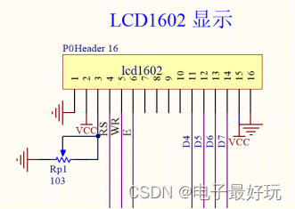
Figure 2.4 LCD module
2.5 Control buttons and independent buttons
This design has two control buttons and an independent button, which can realize functions such as reset, maximum temperature setting, and minimum temperature setting.

Figure 2.5 Control key module
2.6 Temperature sensor module
This design uses a DS18B20 digital temperature sensor, which is a temperature sensor that integrates temperature detection and digital data output and has good anti-interference ability.

Figure 2.6 Temperature sensor module
2.7 Buzzer module
The buzzer module acts as an alarm. When the measured temperature is higher than the set maximum temperature or lower than the preset minimum temperature, the system will send a high-level signal to the buzzer, thereby generating an alarm sound. When the detected human body temperature is higher than 38°C, (the preset maximum temperature of human body health temperature is 38°C), an alarm will be issued to determine whether the tester has fever symptoms.

Figure 2.7 Buzzer module
2.8 Power Circuit
The power supply circuit is to increase the 3.3V constant voltage for the whole system, and is composed of DC power supply interface and key switch.

Figure 2.8 Power Module
Chapter 3 Software Design
3.1 Overall program processing

Figure 3.1 Software program flow chart
The program flow chart is shown in Figure 3.1. From the figure, we can clearly understand the working process of the system. Supply a constant voltage source, press the switch, the temperature measurement system starts to work, and the display shows the default temperature range. At this time, the temperature measurement range can be adjusted by pressing the button to determine the normal body temperature range of the human body; then the sensor is used to collect the measured human body temperature , when the collected data is not within the interval, the buzzer alarm will be triggered, so that the temperature of the experimental object is known to be abnormal, and the temperature detection and alarm of the human body can be realized.
3.2 LCD display
When the system starts to work, the LCD screen displays the default temperature range, numerical letters, etc., and displays the ambient temperature measured by the sensor. When the human body temperature measured by the DS18B20 temperature sensor is obtained, the LCD screen displays the timely measured temperature.
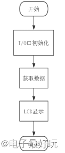
Figure 3.2 Liquid crystal display flow chart
3.3 Key display
The matrix key flow chart is shown in Figure 3.3. The key function identifies the current system mode, adjusts the value of the temperature range through the key, and displays it on the LCD screen.
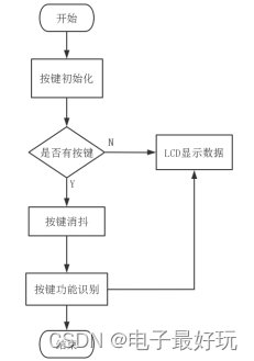
Figure 3.3 Key program flow chart
3.4 Temperature acquisition
The temperature acquisition process is the most critical part of this project. A DS18B20 temperature sensor with stable functions is used. After the serial port is initialized, the enable terminal will send data and wait for the temperature sensor to respond. The system that receives the response will write the value on the LCD1602 and perform temperature monitoring. convert.

Figure 3.4 Flow chart of temperature acquisition program
Chapter 4 Hardware Debugging
After the system is powered on, the temperature is displayed normally, and the LCD display content is shown in Figure 4.1.

Figure 4.1 System temperature display
The first line shows that the current indoor temperature is 27.7°C, the second line shows the temperature range, the highest temperature is: H, 38.0°C, and the lowest temperature is: L, 10.0°C.
Set the appropriate temperature range. The normal temperature range of the human body is 36.0-37.3°C. The default temperature range can be adjusted to facilitate quick measurement and temperature alarm. The adjustment process is shown in Figure 4.2.


(a) Temperature upper limit adjustment diagram (b) Temperature lower limit adjustment diagram
Figure 4.2 Temperature adjustment diagram
If the temperature range is exceeded, the system will give a high-level signal to the buzzer, the buzzer will give an alarm, and the breathing light will flash, as shown in Figure 4.3.

Figure 4.3 Alarm display diagram
Chapter 5 Summary
Since the outbreak of the new crown epidemic in the spring of 2020, the temperature of the human body is an important parameter for monitoring the new crown epidemic . How to accurately and quickly complete temperature measurement and temperature display requires a new type of temperature measurement tool to replace the traditional temperature measurement tool . In this context, the study of this design is of great significance.
This design uses the STM32F103C8T6 development board, which is an enhanced development board in the STM32 series. It has the advantages of low power consumption and high cost performance, and is the best choice for this project. The temperature sensor is a DS18B20 temperature sensor, which has the advantages of strong anti-interference ability and low power consumption. In the design process, the selection and collocation of the hardware part is a question worthy of discussion, and different types of components have different effects on the design results. Consult and understand the electrical characteristics of various hardware, understand its working principle, working environment, and in the process of assembling and welding components, you need to pay attention to some problems such as pin connection, false soldering and missing soldering, and only ensure that the hardware part is correct. , the software part can be used normally. After the hardware part is finished, the design of the software part is the top priority in this project. The software writing tool used in this project is KEIL5. In the software part, this design is mainly divided into four modules, namely the main function call module, system integration module, key control module, and LCD display module. Write the functions of each module separately, and integrate the modules in the final stage of design . After many times of test data analysis, the temperature measurement accuracy of this design can reach ±0.1°C, the temperature measurement error can reach ±0.5°C, each temperature measurement time does not exceed 5 seconds, and the over-temperature alarm function can be realized, which basically realizes the design. all the functions you need.
In the process of design and implementation , the design of the software and hardware has shortcomings. For example, the temperature detection module of the hardware part is gradually rising in temperature instead of directly displaying the detected temperature value, and the software part does not refine the function. integrate. After that, through further study, the problems existing in the design will be solved, and the design will be better improved.
appendix:

Hardware overall circuit diagram