Hikvision industrial camera IO trigger input and output wiring diagram
1 Camera I/O pin interface definition
| pin | Signal | I/O signal source | illustrate | cable color |
|---|---|---|---|---|
| 1 | DC_PWR | – | camera power | orange |
| 2 | OPTO_IN | Line 0+ | Optocoupler isolated input | yellow |
| 3 | GPIO | Line 2 | Configurable input or output | purple |
| 4 | OPTO_OUT | Line 1+ | Optocoupler isolated output | blue |
| 5 | OPTO_GND | Line 0/1- | Optocoupler isolated signal ground | green |
| 6 | GND | Line 2- | camera power ground | Ash |
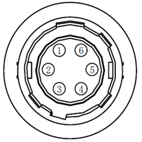
*The color of the cable in the table is drawn according to the standard 6pin cable of Hikvision, and the third-party cable corresponds to the line label by itself
2 Camera line0 input wiring method
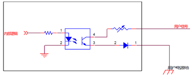
2.1 Equivalent circuit diagram of camera line0 input
The maximum input current for Line 0 is 25 mA. The input logic low level is 0~1 VDC, and the input logic high level is 1.5-24VDC. The
input level is between 1V~1.5V. The circuit state is unstable. Please try to avoid the input voltage in this range. The
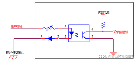
camera IO input part can be understood as A simple light-emitting diode, the process of lighting up this diode is the process of triggering success
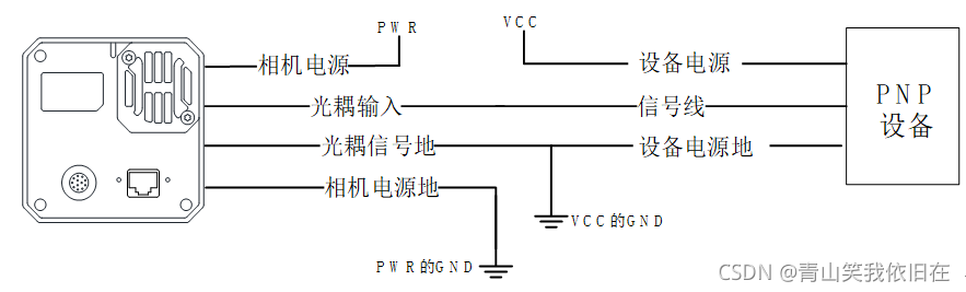
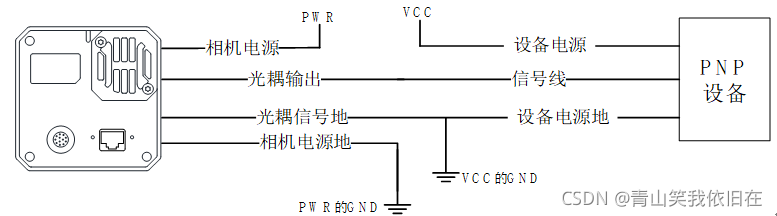
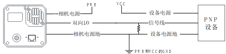
2.2 Camera line0 input wiring diagram
- PNP device connection
If the potential difference between the signal line and the device power ground is greater than 12V, it is recommended to connect a 1k resistor in series for protection
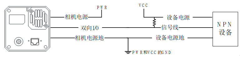
- NPN device connection
Wiring method 1: pull-up power supply to provide driving voltage to trigger the camera (recommended)
- If the VCC of the NPN device is 24 V, it is recommended to use a pull-up resistor of 2 ~ 4.7 KΩ.
- If the VCC of the NPN device is 12 V, it is recommended to use a 1 KΩ pull-up resistor
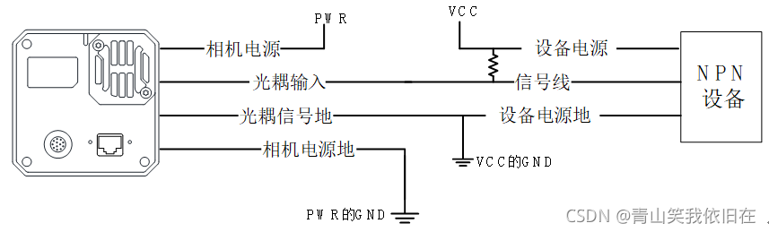
Wiring method 2: Switch to ground, turn on the circuit to trigger the camera

2.3 Camera parameter settings
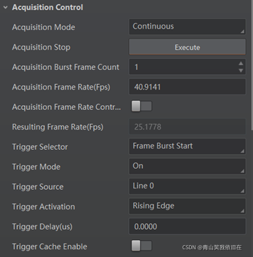
The trigger parameter setting steps are as follows:
- Configure the trigger mode: Trigger mode is set to on
- Configure trigger source: trigger source, select line0 or line2 (depending on hardware wiring)
- Configure trigger polarity: trigger activation, rising edge is selected by default (rising edge, falling edge, high, low level, etc. can be configured)
- Configure trigger delay: trigger delay, default 0us
- Configure the trigger signal cache: trigger cache enable, off by default.
The steps to set the filter parameters are as follows:
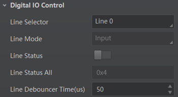
- Select input signal source: line selector, select line0 or line2 (depending on hardware wiring)
- Configure filter parameter size: line debouncer time, default 50us
3 Camera line1 output wiring method
3.1 Equivalent circuit diagram of camera line1 output
The maximum output current of Line 1 is 25 mA. With an external voltage of 3.3 V and an external resistor of 1 KΩ, the output logic low level is 575 mV and the output logic high level is 3.3 V
3.2 Camera line1 output wiring diagram
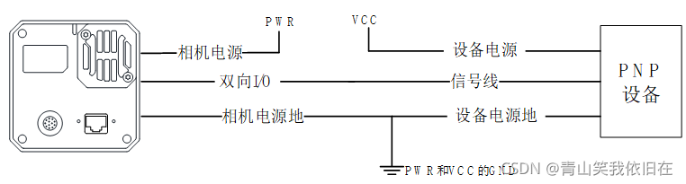
- Output PNP device
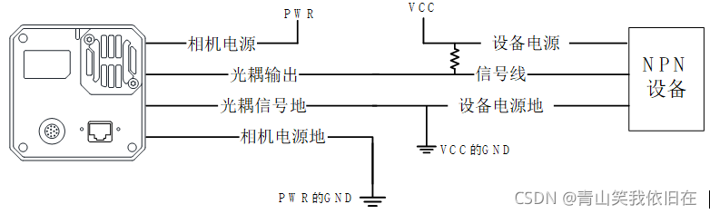
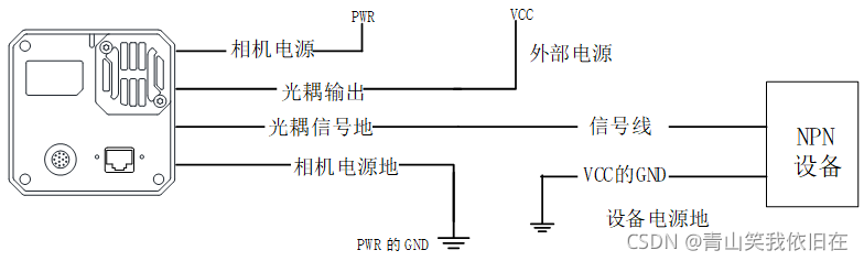
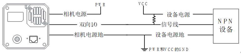
- Output NPN device
Wiring method 1: Pull-up power supply provides drive voltage output to trigger external devices (recommended)
- If the VCC of the NPN device is 24 V, it is recommended to use a pull-up resistor of 1 ~ 4.7 KΩ
- If the VCC of the NPN device is 12 V , it is recommended to use a 1 KΩ pull-up resistor
Wiring method 2:
When the potential difference between VCC and signal ground is greater than 12V, it is recommended to connect a 1K resistor in series between VCC and the camera output
3.3 Camera parameter setting
Camera hardware output, reference usage is mainly divided into two categories
- Strobe output, shooting with strobe light source, IO output follows the exposure, and the output cycle is synchronized with the exposure cycle
- Software output, user-defined time output, user independent control, output OK or NG signal when necessary
Therefore, there are two different configuration methods
-
Usage 1: strobe output with strobe light source, IO output and exposure synchronization
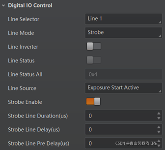
a) Configure input signal source: select line1 or line2 (depending on hardware wiring)
b) Line mode is strobe option, no parameter configuration
c) Test line inverter , click repeatedly to test the level change and verify whether the wiring is normal
d) Configure the output event source Line source: select Exposure Start Active
e) Configure the output signal timing: StrobeLineDuration (signal duration, default 0, duration is equal to exposure time; set Other values are other value time), StrobeLineDelay (delayed output, how long to delay output from exposure start), StrobeLinePreDelay (early output, exposure delay start) f)
enable output, strobe Enable (after enabling, IO output output following exposure start) -
Usage 2: Event source Software output, IO output is synchronized with LineSource
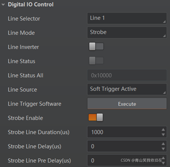
a) Configure input signal source: select line1 or line2 (depending on hardware wiring)
b) Line mode is strobe option, no parameter configuration
c) Test line inverter, repeat Click to test the level change and verify whether the wiring is normal
d) Configure the output event source Line source: Select Soft Trigger Active
e) Configure the output signal timing: StrobeLineDuration (signal duration, default 0, when using Soft Trigger Active, you need to configure a Duration, such as 1000), StrobeLineDelay (delayed output, how long to delay output from the signal release), StrobeLinePreDelay (advance output) f)
Enable output, strobe Enable configuration is turned on
g) When the camera output signal is required, click line The button of the trigger software; Execute execution
4 camera line2 configurable input and output wiring method
There is no big difference in wiring between Line2 and line0, line1. It should be noted that the signal ground of line2 is shared with the power supply ground of the camera, which is quite different from line0 and line1.
4.1 line2 input use
- When the input device is PNP, a 330Ω resistor needs to be pulled down
- When the input device is NPN, when inputting with line0, the wiring method is the same
4.2 line2 output use
When Line2 is configured as IO output, the wiring method is the same as that of Line1, and the software parameter configuration method can also refer to Line1;
- External is a PNP device
- External is an NPN device
- if the VCC of the NPN device is 24 V, it is recommended to use a pull-up resistor of 1 ~ 4.7 KΩ.
- If the VCC of the NPN device is 12 V, it is recommended to use a 1 KΩ pull-up resistor.
5SDK secondary development
Invoke the secondary development of Hikvision Industrial Camera and integrate it into your own software. The configuration sequence is consistent with the operation sequence above the MVS software. You can call it by referring to the general interface. Other articles in this blog have introduced it. You can link it to see 1. Hikvision Industrial
Camera Parameter setting: Hikvision industrial camera parameter setting and acquisition
2. Hikvision industrial camera function module - IO input and output control: Hikvision industrial camera function module - IO input and output control