Intel 80386 memory management
There are some reference articles
1. Memory management
Memory management is a hardware mechanism in which the microprocessor addresses physical memory on bus addresses. However, in order to provide the program with a larger space than the physical memory capacity, the concept of virtual memory is introduced, which is implemented with the support of external memory (such as a disk), and the commonly-called virtual address is called a logical address. For 80386, there is both segment management and page management. The management of segments and pages is the responsibility of the operating system, and the 80386 provides a management mechanism from the hardware.
To summarize which mechanisms will be used:
| mechanism |
|---|
| segment management mechanism |
| Segment page management directly |
| secondary page table |
| fast watch |
We will use registers in storage management, here is an overview.
The 80386 microprocessor has a total of 34 registers in 7 categories, general-purpose registers, segment registers, instruction pointer and flag registers, system address registers, control registers, debug registers, and test registers.
Schematic diagram of the first four types of registers:
[External link picture transfer failed, the source site may have an anti-leeching mechanism, it is recommended to save the picture and upload it directly (img-YrP0FJQA-1651556465675) (C:\Users\15191\Desktop\ComputerScienceClassNote\OS\CPU\80386 register.png )]
2. Three working modes of Intel 80386 microprocessor
Three ways of working:
- real address mode
- Virtual address protection mode
- Virtual 8086 way.
1. Real address method
386 is in this mode after hardware reset, and can only use the lower 20-bit address of the 32-bit address bus, and the addressing space is 1MB.
At this time, it is an 8086/8088 microprocessor. The difference is that it can not only run all 8086/8088 instructions, but also run 32-bit arithmetic instructions.
The system initialization area is in the FFFFFFF0H-FFFFFFFFH storage area.
This mode is set to be compatible with 8086, and it can also be changed from the real address mode to the protected virtual address mode.
The physical address is the low 20-bit address code sent by the 8386 chip address lead. After memory decoding, a storage unit is selected for reading and writing. The physical address can be represented by a 5-digit hexadecimal address.
The memory address segmentation is to divide the 1MB memory space into several segments, each segment has a maximum capacity of 64KB, and the upper 16-bit binary code of each segment head address is the segment number of the segment (called segment base address) .
After the memory adopts segmentation management, the segment addresses are stored in the segment registers CS, DS, SS, and ES, and different values are set for the segment registers to make the segment registers of the microprocessor point to different segments in the memory.
The offset address is the offset within the segment relative to the first address of a segment. To form the physical address, shift the segment address to the left by 4 bits to obtain the segment base address, and then add the offset address value to form a 20-bit physical address.
2. Virtual address protection method
When the lowest bit of Intel 80386/486's key control register CR0 is the PE (Protection Enable) protection mode enable bit, it is used to start the CPU into the virtual address protection mode. **PE=0 means that the CPU works in real address mode, and PE=1 means that the CPU works in virtual address protection mode.
The memory management mechanism of 80386/486 adopts segmentation and paging management.
The segmentation mechanism is to convert the logical address into a linear address first , and then use the paging mechanism to convert the linear address into a physical address.
(The two-dimensional address of the segment is converted into a linear address through the segment table, and then converted into a physical address through the page table. This is what our MMU does)
The logical address is composed of a segment address and an offset. It is a method of expressing the memory address in the program. Logical address = segment address: offset address. When paging is disabled, linear addresses become physical addresses.
(1) Segment selector and segment register
The segment register is used to store the segment selector. The segment registers include CS, DS, SS, ES, FS, and GS. The segment selector is 16 bits, and the offset bit is a 32-bit long field.
The segment selector is composed of 16 bits, which are further divided into 3 parts, namely: 13-bit index field, 1-bit indicator field TI and 2-bit request privilege level field RPL.
| segment selector | ||
|---|---|---|
| 13-bit index field | 1-bit indicator field TI | 2-bit request privilege level field RPL |
- The index finger specifies the entry of the corresponding segment descriptor placed in the GDT or LDT.
- TI flag well-known segment descriptor is in GDT (TI=0) or in LDT (TI=1).
- RPL indicates the current privilege level of the CPU when the current segment selector is loaded into the CS register.
(2) Segment descriptor
Each segment is represented by a 64-bit (8-byte) segment descriptor , which describes the characteristics of the segment.
Segment descriptors are stored in **Global Descriptor Table (GDT) or Local Descriptor Table (LDT)** (these two are our segment tables, there are global segment tables and local segment tables).
Since each segment descriptor is 8 bytes, the relative address of the segment descriptor in GDT or LDT is the value of the highest 13 bits of the segment selector (that is, the index field of the segment selector) multiplied by 8.
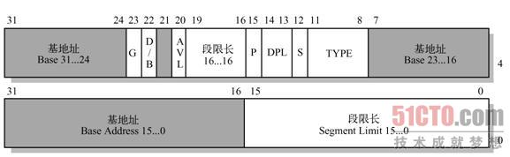
The meanings of the fields and flags in the segment descriptor are as follows:
- 1) Base address field Base (Base address field): contains the linear address of the first byte of the segment.
- 2) Segment limit field Limit (Segment limit field): used to specify the length of the segment. If G=0, the segment length Limit can range from 1 byte to 1MB, and the unit is byte; if G=1, the segment length Limit can range from 4KB to 4GB, and the unit is 4KB.
- 3) Granularity flag G : if this bit is 0, the segment unit is byte; if the bit is 1, the segment unit is 4KB. It can be understood in combination with the segment limit field Limit.
- 4) Segment type field TYPE (Type field) : describes the type characteristics of the segment and its access rights. The interpretation of this field depends on the descriptor type flag S, which is interpreted by S as a code or data segment descriptor, or a system descriptor. The encoding of the TYPE field is different for code, data, or system descriptors.
- 5) Descriptor type flag S (Descriptor type flag) : If S=0, a segment descriptor is a system segment descriptor, such as storing key data structures such as LDT; if S=1, storing code or data segments Descriptor.
- 6) Descriptor privilege level field DPL (Descriptor privilege level) : The privilege level of the descriptor is used to control access to the segment, indicating the minimum priority required by the CPU to access this segment. Privilege levels range from 0 to 3. Level 0 is the highest and level 3 is the lowest.
- 7) Segment presence flag P (Segment present) : used to indicate whether a **segment is in memory (P=1) or not in memory (P=0). **Always set this flag to 1 for linux, since it never swaps entire segments to disk.
- 8) D/B (Default operation size/default stack pointer size and/or upper bound) flag (Default operation size/default stack pointer size and/or upper bound): An executable code segment is described according to the segment descriptor , The extended data segment is also a stack segment. This flag has different functions. For 32-bit code and data segments, this flag should always be set to 1; for 16-bit code and data segments, this flag should be set to 0.
- 9) Available and reserved bits (Available and reserved bits) : used by the operating system, but linux ignores this field.
(3) Segment description table and segment description table register
The 80386/486 microprocessor has a global descriptor table register GDTR , a local descriptor table register LDTR and an interrupt descriptor table register IDTR , through which to find the global descriptor table GDT , local descriptor table LDT and interrupt descriptor table IDT respectively .
(storage segment header pointer)
(4) Segmentation and paging mechanism
The segmentation unit converts logical addresses into linear addresses.
Since the upper 14 bits of the segment selector (13-bit index number and 1-bit TI bit) are used for segment descriptor selection, the maximum number of segments in the virtual memory can reach 16K (2 to the 14th power) ;
When the TI bit is 1, the local address space is accessed . Usually when defining a GDT, all tasks share the global address space. If each process needs to create additional segments in addition to storing segments in the GDT, an LDT can be created to independently occupy the local address space.
The address and size of GDT in memory are stored in gdtrthe control register, and the address and size of the LDT currently being used are stored in ldtrthe control register.
How a logical address is converted to the corresponding linear address. The segmentation unit performs the following operations:
- 1) Check the TI field in the segment selector to determine which descriptor table (GDT or LDT) the segment descriptor is stored in.
- 2) The index field of the segment selector is multiplied by 8, and ** calculates the relative address of the segment descriptor in the descriptor table (GDT or LDT, determined by the previous step). **The first address of the descriptor table is saved in
gdtrthe control register orldtrthe control register (which register is saved is determined by the previous step). - 3) The value of the base field in the segment description is the segment base address, plus the logical address, the linear address is obtained.
The paging unit converts linear addresses into physical addresses.
In the virtual address protection mode (that is, the PE bit of the control register CR0 is 1), the highest bit PG in the control register CR0 determines whether to start the paging mechanism. When PG=1, the paging mechanism is valid, and the linear address can be converted into a physical address. ;
When PG=0, the paging mechanism is invalid, and the linear address is directly used as a physical address.
The 32-bit linear address is divided into 3 parts: the highest 10 bits are the page directory index, the middle 10-bit page table index, and the lowest 12-bit offset .
The conversion of the linear address is divided into two steps, both based on the conversion table, the conversion table of the first step is called the page directory table (page directory) , and the conversion table of the second step is called the page table (page table) .
That is, a two-level page table mechanism is used here
Review the page table mechanism:
- Linear addresses are divided into fixed-length groups called pages; the paging unit divides all RAM into fixed-length groups called page frames.
- Each page frame is the same length as the page, and a page frame contains a page. A page frame is a part of the memory; a page is a logical concept, which refers to both a set of linear addresses and the data contained in this set of addresses. The data contained in a page can be in memory or on disk middle.
How a linear address is translated into the corresponding physical address. The paging unit performs the following operations:
- 1) The page directory base address register CR3 provides the page frame address of the page directory (that is, the page directory base address) , starting with the page directory base address, plus the value of the page directory index in the linear address, it is found in the page directory table Page directory entry, the base address value of the page table can be obtained from the page directory entry (its lower 12 bits are 0).
- 2) Start with the base address value of the page table and add the value of the page table index in the linear address to obtain the physical address of the page frame (that is, the first physical address of the page frame). The physical address of the page frame is added to the offset of the linear address to obtain the physical address of the linear address in the page frame.
Starting from the 80386, the paging unit of the Intel microprocessor handles 4KB pages, and the starting address of each page is always a linear address whose lower 12 bits are 0. Paging management maps any page in linear address space to a page in physical space. The main purpose of using the paging management mechanism to realize the translation mapping from linear address to physical address is to facilitate the realization of virtual memory. The purpose of using the secondary page table is to reduce the amount of RAM required for each process page table. If only the first-level page table is used, then there are 2 to the 20th power table entries to represent the page table of each process, and 4 bytes for one table entry requires 4MB RAM to represent all page table entries.
In a two-level page table, there are page directory entries and page table entries, which have the same format. (It is a two-level page table, you can review it moderately)
- Page frame address: The starting address of a page is called the page frame address . Since the size of a page is 4KB, in a page table entry, the upper 20 bits are used to describe the address of a page frame, while the lower 12 bits are used to describe the control and status of the page. In the first-level page directory, the page frame address points to the start address of the corresponding page table; in the second-level page table, the page frame address points to the start address of the page in the memory.
- Existence bit P: P=1, indicating that the referred page (page table entry) is in the physical memory; P=0, indicating that the referred page (page table entry) is not in the physical memory. When the P of the page table entry or page directory entry required to perform a linear address translation is 0, then the paging unit stores the linear address in the control register CR2, and generates No. 14 exception: page fault exception.
- Read/write bit R/W: R/W=1 write, otherwise read. It is used to indicate the access right to the page (page table), which has nothing to do with address translation.
- User/monitor bit U/S: used to indicate the privilege level required to access the page (page table).
- Access bit A: Used to indicate whether the page pointed out by this item has been read or written. If A=1 in the directory entry, it means that the page table indicated by the item has been accessed; if A=0 in the page table entry, it means that the page in the memory indicated by the page table item has not been accessed. The paging unit never resets this flag, but it must be done by the operating system .
- Dirty bit D: Only used in page table entries. This flag is set whenever a page frame is written.
- Available field AVL: This field has 3 bits in total and is used by system software designers. Information related to page usage can be placed in this field to help analyze which pages should be moved out of memory.
- PWT and PCD: Control how the hardware cache handles pages (page tables) .
Refer to the request page table:
| page number | memory block number | status bit | access field | modify bit | External memory address |
|---|---|---|---|---|---|
| old | old | new | new | new | new |
| This is implicitly stored by the continuity of the page table (in fact, it also uses the random storage characteristics of the continuous space , and the mapping is fast access) | The base address of the page in memory | 1 bit, whether to load into memory | Record the number of recent visits or the time of the last visit for the replacement algorithm | Whether the page has been modified after being loaded into memory | The location of the page in external memory |
Compare
| page frame address | presence bit P | Read/Write bit R/W | User/Monitor bit U/S | access bit A | Dirty bit D | Availability Domain AVL | PWT and PCD |
|---|---|---|---|---|---|---|---|
| physical address | status bit | protection mechanism | protection mechanism | modify bit |
(5) Translation look-aside buffer TLB
(That is, the fast table mechanism is implemented here)
From the conversion process of the linear address above, it can be seen that an address conversion requires two memory accesses: one access to the page directory table and one access to the page table.
In order to speed up the address translation process, the 80386 sets a Translation Lookside Buffercomponent called the translation look-aside buffer TLB ( ) inside the chip.
Each item of the TLB stores 32 linear address values ((the upper 20 bits of the linear address, that is, the base address of the page) and the corresponding physical address value (the upper 20 bits of the physical address, that is, the base address of the page frame), and Contains properties such as access rights to the page.
When the linear address is being translated, the upper 20 bits of the linear address are compared with the value of the linear address in the TLB.
- If not found, the corresponding physical address is calculated through the above conversion method, and the physical address is stored in a TLB entry; (miss, replace, use full replacement strategy)
- If it can be found, the base address of the page frame can be obtained, and the physical address can be obtained by adding the lower 12 bits of the linear address. (hit)
Since the TLB has 32 items, it can represent the correspondence between the currently commonly used 32 pages and page frames, and each page is 4KB, so the TLB actually represents 128K ((32*4KB=128KB)) linear addresses and physical addresses corresponding relationship.
Due to the limitations of programs and data, and the translation information of 128K addresses can be accommodated in the TLB, address translation using the TLB has a very high hit rate, generally up to about 98%.
When the value of the CPU's control register CR3 is modified, the hardware automatically invalidates all entries in the TLB because a new set of page tables is used. In this way, subsequent conversions to the same linear address can be quickly obtained.
3. Virtual 8086 mode
Compared with the real address method, it has an optional paging function. In this mode, the base address in the segment register is moved to the left by 4 bits and then the offset address, and the result is a linear address. If the paging function is enabled, the paging mechanism must be used to convert it into a physical address. If it is not enabled, the linear address is the physical address.
3. Protection mechanism of Intel 80386
1. Segment level protection
(1) Protection between different tasks
In order to protect different tasks, it is achieved by placing each task in a different virtual address space.
Each task defines the mapping function from the virtual address to the physical address, and the mapping function will also switch after the task is switched.
Since each task has a set of independent mapping tables, that is, has different address conversion functions , when the processor switches and executes a new task, the conversion table for switching tasks for the new task is an important part. For different tasks, they may have the same virtual address, but due to the respective mapping functions, the physical addresses of different tasks are different.
(2) Protection within the same task
A protection mechanism within the same task is more suitable for protecting the operating system, so that the operating system is shared by all tasks and can be accessed in each task from being corrupted by applications.
The virtual address space that each task can share is called the global address space;
The virtual address space used by only one task, that is, the portion of the virtual address that is not shared by any other task, is called the local address space.
The operating system defines a common area in the virtual address space, and each task can use the virtual address space and map to the same physical address.
In virtual address protection mode, the segment level protection of 80386/486 microprocessor is divided into 4 levels of protection. Each task is separated where:
- Privilege level 0 is the highest reliability privilege level;
- Privilege level 3 is the least reliable privilege level.
Each privilege level has its own independent program stack to avoid protection issues associated with shared stack areas.
When a program is executed from one privilege level to another, the stack used by the program changes from the stack segment of the original privilege level to the stack segment of the new privilege level. For the stack segment register SS, the descriptor privilege level (DPL) must be equal to the privilege level (CPL) of the current code segment.
Each memory segment is associated with a privilege level, and the program can only access the corresponding segment with sufficient privilege level. Privilege levels are represented by the numbers 0, 1, 2, and 3, with higher numbers having lower privileges. When comparing privilege levels, use terms such as "inside" or "inner" to denote higher privilege levels and use terms such as "outside" or "outer" to denote lower privilege levels.
- In privilege level 0, the operating system kernel is usually configured, mainly including task and memory management, communication between tasks and I/O devices, etc.
- In privilege level 1, programs that do not belong to the system standard services of the kernel, such as file sharing, data communication, etc.
- In privilege level 2, custom programs that extend the operating system are usually configured. These are services that depend on the kernel, such as database management programs or logical file access systems.
- Privilege level 3 is assigned to user applications. At this level, applications and the operating system should be isolated from each other without affecting each other.
- Not all 4-level privilege levels must be used, and it is determined by the operating system itself.
2. Page protection mechanism
The Intel 80386 provides page-level protection. The paging mechanism** only distinguishes two privilege levels. Privilege levels 0, 1, and 2 are collectively called system privilege levels, and privilege level 3 is called user privilege levels. **The protection attribute bits R/W and U/S in the page directory entry and page table entry are used to protect the page.
- (1) The **R/W bit indicates whether the page specified by the entry can be read, written or executed. **The write protection of the page by the R/W bit only works when the processor is at the user privilege level; if the processor is at the system privilege level, the R/W bit is ignored, that is, it can always be read, written or executed. If R/W=1, the page specified by the entry can be read, written or executed; if R/W=0, the page specified by the entry can be read or executed, but cannot be written to the specified page .
- (2) The U/S bit represents the user/system attribute bit , which is used to indicate the privilege level required to access the page (page table). If U/S=1, the page specified by the entry is a user-level page, which can be accessed by programs executed under any privilege level; if U/S=0, the page specified by the entry is a system-level page, which can only be accessed by the system Program access executed at a privileged level.
In the process of converting a linear address into a physical address, a page-level protection check is performed. If a page is accessed (read/write/execute) in violation of the provisions of the page protection attribute, a page exception will be caused.