What is camera calibration?
1. Checkerboard image collection
Single Camera Calibrator App supports checkerboard, circle grid and custom detector patterns. See Calibration Patterns for details on these patterns and a PDF file containing printable patterns .
Share a website that can generate various calibration boards: https://calib.io/pages/camera-calibration-pattern-generator
(1) In this paper, select the checkerboard pattern, open matlab, and enter the command line:
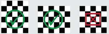
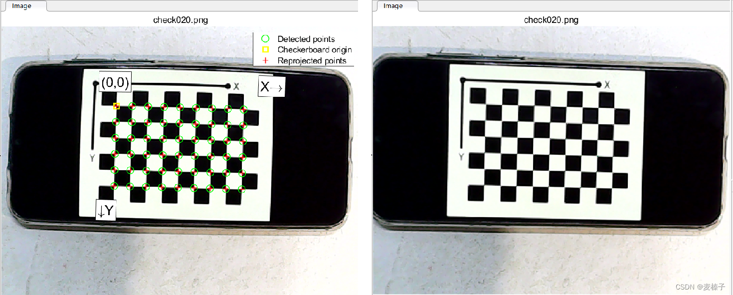
open checkerboardPattern.pdfA checkerboard pattern is the calibration pattern most commonly used for camera calibration. The control points for this mode are the corners located inside the board. Since the corners are so small, they are generally immune to perspective and lens distortion. The calibrator app can also detect parts of the checkerboard, which is useful when calibrating cameras with wide-angle lenses. Use a board that contains an even number of squares along one side and an odd number of squares along the other, with two black corner squares along one side and two white corner squares along the other side. This enables the application to determine the orientation and origin of the pattern. The calibrator designates the longer side as the X direction. A square checkerboard pattern can have unexpected results on the camera's extrinsics.
(2) Paste the checkerboard on a flat surface. Surface imperfections can affect the accuracy of the calibration. This article uses mobile phone screen display.
(3) Measure one side of the chessboard square. You need this measurement for calibration. The size of the squares will vary depending on the printer settings. In this paper, the side length of the square is measured to be 7mm.

(4) Run dofbot_ws/src/yolox_tiny_waste_sort/take_photos.ipynb to take 20 checkerboard pictures in different poses

2. Start calibration
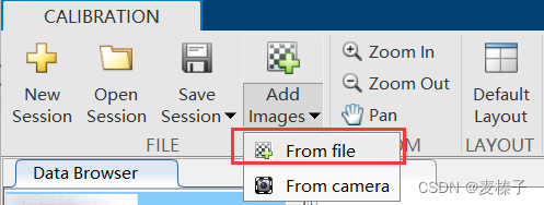
(1) Open Matlab, enter the command line:
cameraCalibrator(2) Import the 20 checkerboard pictures taken, and input the side length of the grid as prompted: 7mm
(3) "Options" select the number of radial distortion coefficients to be 3, check Tangential distortion
(4) Click "Caliberate" to start calibration
(5) Export the calibration result to the workspace (you can export it again after adjusting it to your satisfaction)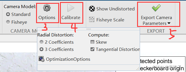
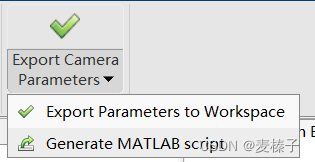
(6) Generate MATLAB script
Under "Export Camera Parameters" (for standard camera models) or "Export Fisheye Parameters" (for fisheye camera models), select "Generate MATLAB Script" to save the camera parameters into a MATLAB script, enabling you to reproduce Steps for a calibration session.
Note: You cannot generate MATLAB scripts for custom pattern camera parameters defined using the vision.calibration.PatternDetector class.
3. Evaluate the calibration results
Calibration accuracy can be assessed by examining reprojection errors, examining camera extrinsics, or looking at the unwarped image. For best calibration results, use all three evaluation methods.
3.1 Visualization of camera extrinsic parameters
The 3-D extrinsic parameter map provides a camera-centric view of the pattern and a pattern-centric camera view. A camera-centric view is helpful if the camera is stationary when the image is taken. A pattern-centric view is helpful if the pattern is stationary. You can click and drag the graphic to rotate it. Click on a board (or camera) to select it. The highlighted data in the visualization corresponds to the selected image in the list. Check the relative positions of the pattern and camera to see if they match what you expect. For example, a pattern that appears behind a camera indicates a calibration error.

Command line input:
figure;
showExtrinsics(cameraParams, 'CameraCentric');
3.2 Reprojection error
The reprojection error is the distance between the detected point and the corresponding reprojected point, in pixels. The camera calibrator app calculates the reprojection error by projecting points from pattern-defined world coordinates to image coordinates. The application then compares the reprojected points with the corresponding detected points. In general, an average reprojection error of less than one pixel is acceptable.

The Camera Calibrator app displays reprojection error in pixels with a histogram. This graph helps you determine which images are adversely affecting the calibration. You can select a bar chart entry to select an image and remove that image from the list of images in the data browser pane.
Reprojection Error Bar Graph
The bar graph shows the average reprojection error per image, as well as the overall average error. Bar labels correspond to image IDs. Highlighted bars correspond to selected images.
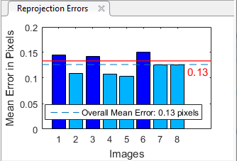
Select an image using one of these methods.
- Click the corresponding bar in the graph.
- Select an image from the list of images in the data browser pane.
- Adjusted population mean error. Slide the red line up or down to automatically select all images with an average error greater than the specified value.
Command line input:
figure;
showReprojectionErrors(cameraParams);
3.3 View distortion corrected image
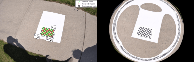
To see the effect of undistorting the lens, select "Show Undistorted" in the "Calibration" tab. If the calibration is accurate, distorted lines in the image preview will become straight.
NOTE: Even if the reprojection error is low, it is important to check the undistorted image. For example, if the pattern covers only a small part of the image, the deformation estimate may be incorrect, even if the calibration results in little reprojection error. This image shows an example of incorrect estimation for this type of single machine calibration.
3.4 Print error results
Command line input:
displayErrors(estimationErrors, params);4. Improve calibration accuracy
To improve calibration results, you can remove images with high error, add more images, or modify calibrator settings.
Consider adding more images if:
- You have less than 10 images.
- The calibration pattern does not cover enough of the image.
- The calibration pattern does not vary enough in orientation relative to the camera.
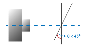
Consider removing images if they:
- has a high average reprojection error.
- Vague.
- Contains a calibration pattern that is greater than 45 degrees relative to the camera plane.
References
[1] Zhang, Z. “A Flexible New Technique for Camera Calibration.” IEEE Transactions on Pattern Analysis and Machine Intelligence. 22, no. 11 (November 2000): 1330–34. https://doi.org/10.1109/34.888718.
[2] Heikkila, J., and O. Silven. “A Four-step Camera Calibration Procedure with Implicit Image Correction.” In Proceedings of IEEE Computer Society Conference on Computer Vision and Pattern Recognition. 1106–12. San Juan, Puerto Rico: IEEE Comput. Soc, 1997. https://doi.org/10.1109/CVPR.1997.609468.
[3] Scaramuzza, Davide, Agostino Martinelli, and Roland Siegwart. "A Toolbox for Easily Calibrating Omnidirectional Cameras." In Proceedings of IEEE International Workshop on Intelligent Robots and Systems 2006 (IROS 2006), 5695–701. Bejing, China: IEEE, 2006. https://doi.org/10.1109/IROS.2006.282372
[4] Bouguet, J. Y. “Camera Calibration Toolbox for Matlab.” Computational Vision at the California Institute of Technology.