SD card driver for STM32CubeMx
1. Introduction to SD card
SD memory card (Secure Digital Memory Card) is a new generation of high-speed storage device based on semiconductor flash memory. The technology of SD memory card is developed from MMC card (MultiMedia Card) format, and SDIO (SD Input/Output) card is developed on the basis of compatible SD memory card. This compatibility includes mechanical, electronic, electric, signal and software , SD and SDIO cards are commonly referred to as SD memory cards.
SD card has high memory capacity, fast data transfer rate, great mobility flexibility and good security, it is widely used in portable devices, such as digital cameras, tablet PCs and multimedia players, etc.
SD card supports two bus modes: SD mode and SPI mode. Among them, SD mode adopts 6-wire system, and uses CLK, CMD, DAT0~DAT3 for data communication. The SPI method adopts a 4-wire system, and uses CS, CLK, DataIn, and DataOut for data communication.
The data transmission speed in SD mode is faster than that in SPI mode. STM32F103ZE has its own SDIO interface driver. The maximum speed can reach 24MHZ in 4-bit mode and 48MHZ in 8-bit bus mode. This chapter will introduce how to use the HAL library to complete the SD card. drive.

2. Introduction to SDIO
SD/SDIO MMC card host module (SDIO) provides operation interface between AHB peripheral bus and multimedia card (MMC), SD memory card, SDIO card and CE-ATA equipment.
The main functions of SDIO are as follows:
- Fully compatible with Multimedia Card System Specification Version 4.2. Three different data bus modes are supported: 1-bit (default), 4-bit, and 8-bit.
- Fully compatible (forward compatible) with earlier Multimedia Card system specification versions.
- Fully compatible (forward compatible) with earlier Multimedia Card system specification versions.
- Fully compatible with SD memory card specification version 2.0.
- Fully compatible with SD I/O card specification version 2.0, supports various data bus modes: 1-bit (default) and 4-bit.
- Fully support CE-ATA function (fully compatible with CE-ATA digital protocol version 1.1).
- Data transfer rate up to 48MHz in 8-bit bus mode
2.1 SDIO bus topology
Communication on the bus is achieved by transferring commands and data.
The basic operation on the multimedia card/SD/SD I/O bus is a command/response structure, such a bus operation realizes information exchange under the command or bus mechanism; in addition, some operations also have data tokens.
The data transmitted on the SD/SDIO memory card is transmitted in the form of data blocks; the data transmitted on the MMC is transmitted in the form of data blocks or data streams; the data transmitted on the CE-ATA device is also transmitted in the form of data blocks transmission.
-
SDIO "No Response" and "No Data" operations

-
SDIO (multiple) data block read operation

-
SDIO (multiple) data block write operation

Note: When there is a Busy (busy) signal, SDIO (SDIO_D0 is pulled low) will not send any data. -
SDIO continuous read operation

-
SDIO continuous write operation

2.2 SDIO function description
- SDIO consists of 2 parts:
● SDIO adapter module: realize all related functions of MMC/SD/SDIO cards, such as clock generation, command and data transmission.
● AHB bus interface: operate the registers in the SDIO adapter module, and generate interrupt and DMA request signals.
-
After SDIO block diagram

is reset, SDIO_D0 is used for data transmission by default. The master can change the width of the data bus after initialization.
If a multimedia card is connected to the bus, SDIO_D0, SDIO_D[3:0] or SDIO_D[7:0] can be used for data transfer. MMC version V3.31 and previous versions only support 1-bit data line, so SDIO_D0 can only be used.
If an SD or SDIO card is connected to the bus, data transfers can be configured by the host using SDIO_D0 or SDIO_D[3:0]. All data lines work in push-pull mode. -
SDIO_CMD has two modes of operation:
● Open circuit mode for initialization (only for MMC version V3.31 or earlier).
● Push-pull mode for command transmission (SD/SD I/O card and MMC V4.2 also use push-pull driver during initialization).
SDIO_CK is the card's clock: 1 bit of command or data is transmitted on the command and data lines every clock cycle. For the Multimedia Card V3.31 protocol, the clock frequency can vary from 0MHz to 20MHz; for the Multimedia Card V4.0/4.2 protocol, the clock frequency can vary from 0MHz to 48MHz; for SD or SDIO cards, the clock frequency can vary from 0MHz to Varies between 25MHz.
- SDIO uses two clock signals:
● SDIO adapter clock (SDIOCLK=HCLK)
● AHB bus clock (HCLK/2)
| pin | definition | illustrate |
|---|---|---|
| SDIO_CK | output | Multimedia card/SD/SDIO card clock. This is the clock line from the host to the card. |
| SDIO_CMD | two-way | Multimedia card/SD/SDIO card commands. This is a bidirectional command/response signal line. |
| SDIO_D[0:7] | two-way | Multimedia card/SD/SDIO card data. These are bidirectional data buses. |
2.3 SDIO adapter
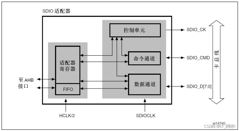
The SDIO adapter is the master device (host) of the multimedia/encrypted digital memory card bus, which is used to connect a group of multimedia cards or encrypted digital memory cards. It consists of the following 5 parts: ● Adapter register module ● Control unit ● Command
channel
●
Data
channel
● Data FIFOs
Note: The adapter registers and FIFO use the clock on the AHB bus side (HCLK/2), and the control unit, command channel, and data channel use the clock on the SDIO adapter side (SDIOCLK).
For a detailed introduction to SDIO, please refer to the STM32 Chinese manual.
3. Hardware interface

| pin | SDIO | SPI |
|---|---|---|
| SDIO_D2(PC10) | data line | |
| SDIO_D3(PC11) | data line | SPI_CS chip select |
| SDIO_CMD(PD2) | control line | SPI_MOSI master output |
| SDIO_SCK(PC12) | clock | SPI_SCK clock line |
| SDIO_D0(PC8) | data line | SPI_MISO master input |
| SDIO_D1(PC9) | data line |
4 Software settings
1. Chip selection

2. Clock configuration


3. SDIO configuration

5 code generation
1. SD initialization
related configuration can refer to STM32 Chinese Reference Manual_V1.0 Section 20.9.2 Clock Control Register SDIO_CLKCR.

void MX_SDIO_SD_Init(void)
{


  /* USER CODE BEGIN SDIO_Init 0 */

  /* USER CODE END SDIO_Init 0 */

  /* USER CODE BEGIN SDIO_Init 1 */

  /* USER CODE END SDIO_Init 1 */
  hsd.Instance = SDIO;
  hsd.Init.ClockEdge = SDIO_CLOCK_EDGE_RISING;//在主时钟SDIOCLK的上升沿产生SDIO_CK
  hsd.Init.ClockBypass = SDIO_CLOCK_BYPASS_DISABLE;//盘路时钟失能
  hsd.Init.ClockPowerSave = SDIO_CLOCK_POWER_SAVE_DISABLE;//始终输出SDIO_CK
  hsd.Init.BusWide = SDIO_BUS_WIDE_1B;//总线宽度
  hsd.Init.HardwareFlowControl = SDIO_HARDWARE_FLOW_CONTROL_DISABLE;//关闭硬件流控制
  //当SD/SDIO卡或多媒体卡在识别模式, SDIO_CK的频率必须低于400kHz。
  hsd.Init.ClockDiv = 6;//时钟分频系数,SDIO_CK=HCLK/(ClockDiv+2)
  if (HAL_SD_Init(&hsd) != HAL_OK)//SD初始化
  {


    Error_Handler();
  }
  if (HAL_SD_ConfigWideBusOperation(&hsd, SDIO_BUS_WIDE_4B) != HAL_OK)//配置总线宽度
  {


    Error_Handler();
  }
  /* USER CODE BEGIN SDIO_Init 2 */
  hsd.Init.ClockDiv=0;//重新设置时钟速度
  /* USER CODE END SDIO_Init 2 */

}
2. SD read and write sector function
In order to facilitate subsequent FATFS file system transplantation, we encapsulate two functions SD card write sector and read sector here.
void SD_WriteDisk(uint8_t *buf,uint32_t sector_add,uint32_t cnt)
{


	HAL_SD_WriteBlocks(&hsd,buf,sector_add,cnt,5000);//SD卡写块
	while(HAL_SD_GetCardState(&hsd)!=HAL_SD_CARD_TRANSFER);//等待数据传输完成

}
void SD_ReadDisk(uint8_t *buf,uint32_t sector_add,uint32_t cnt)
{


	HAL_SD_ReadBlocks(&hsd,buf,sector_add,cnt,5000);//SD卡读块
	while(HAL_SD_GetCardState(&hsd)!=HAL_SD_CARD_TRANSFER);//等待数据传输完成
}
3. The main function
initializes the HAL library, GPIO port, LCD screen (FSMC driver), SD card initialization; obtains the card type and card capacity, and finally calls the SD card read and write sector function to realize the data read and write test.
uint8_t buf_tx[4096]="SD卡SDIO驱动HAL库配置测试数据STM32F103ZET6  -- Ver1.0";
uint8_t buf_rx[4096];
MX_GPIO_Init();
  MX_FSMC_Init();
  MX_SDIO_SD_Init();
  MX_USART1_UART_Init();
  MX_SPI2_Init();
  /* USER CODE BEGIN 2 */
	char buff[200];
	NT35310_Init();//LCD初始化
	LCD_Display_Str(LCD_WIDTH/2-strlen("SD卡初始化")/2*8,20,16,(u8 *)"SD卡初始化",BLACK);
	if(hsd.State!=HAL_SD_STATE_READY)
	{


		LCD_Display_Str(20,40,16,(u8 *)"SD Init  ERR",RED);
	}
	else
	{


		LCD_Display_Str(20,40,16,(u8 *)"SD Init  OK",RED);
		LCD_Display_Str(20,60,16,(u8 *)"卡类型:",RED);
		if(hsd.SdCard.CardType==CARD_SDHC_SDXC)//2.0告诉卡
		{


			LCD_Display_Str(20+8+strlen("卡类型:")*8,60,16,(u8 *)"SDHC",RED);
		}
		else if(hsd.SdCard.CardType==CARD_SDSC)//2.0普通卡
		{


			LCD_Display_Str(20+8+strlen("卡类型:")*8,60,16,(u8 *)"SDSC",RED);
		}
		snprintf(buff,sizeof(buff),"块大小: %d byte\n",hsd.SdCard.BlockSize);
		LCD_Display_Str(20,80,16,(u8 *)buff,RED);
		snprintf(buff,sizeof(buff),"卡容量大小: %.2f GB\n",(hsd.SdCard.BlockNbr>>11)/1024.0);
		LCD_Display_Str(20,100,16,(u8 *)buff,RED);
	}
	LCD_Display_Str(LCD_WIDTH/2-strlen("SD数据读写测试")/2*8,130,16,(u8 *)"SD数据读写测试",BLACK);
	SD_WriteDisk(buf_tx,100,2);
	LCD_Display_Str(20,150,16,(u8 *)"SD写数据: OK",RED);
	SD_ReadDisk(buf_rx,100,3);
	LCD_Display_Str(20,170,16,(u8 *)"SD读数据: OK",RED);
	LCD_Display_Str(20,190,16,(u8 *)"数据内容:",RED);
	LCD_Display_Str(20,210,16,(u8 *)buf_rx,BLUE);
4. Running effect

6. Reference example
HAL library driver SD card example: https://download.csdn.net/download/weixin_44453694/85022733
FATFS file system transplantation: https://blog.csdn.net/weixin_44453694/article/details/118116943