Abstract : In order to solve the problems of insufficient photovoltaic array monitoring and difficult fault location in the photovoltaic power station monitoring system, the author designed an intelligent photovoltaic power station monitoring system that integrates data collection and processing. According to the layout of the photovoltaic power station of the enterprise, the intelligent monitoring system scheme of the photovoltaic power station was proposed, and the hardware selection and software development of the monitoring system were completed. The simulation results show that the monitoring system has the functions of analysis of operating parameters of photovoltaic power plants, real-time online monitoring of photovoltaic equipment, and alarm functions, which ensures the reliable operation and centralized management of photovoltaic power plants.
Key words : photovoltaic power station; intelligent monitoring system; distributed photovoltaic operation and maintenance; real-time online
0 Preface
With the adjustment of the world's energy industry structure and human beings' emphasis on environmental issues, solar energy has become the mainstream of new energy development today with its advantages of abundant resources and flexible layout. More and more photovoltaic power plants are currently in operation. The reliable operation of photovoltaic power plants requires equipment such as combiner boxes and inverters to operate in a fault-free state, which is very important for the status monitoring of photovoltaic equipment. At present, photovoltaic power plants mainly use manual periodic inspection and network monitoring to monitor equipment. Due to limited human resources and insufficient intelligence of the traditional photovoltaic monitoring system, both methods have the problems of insufficient monitoring of photovoltaic arrays and inability to quickly locate faults.
In this context, this paper carried out an intelligent design for the monitoring system of an enterprise's rooftop photovoltaic power station. The monitoring system is equipped with communication modules for photovoltaic power station combiner boxes, inverters and other equipment. It uses RS485 bus to connect with each communication module, transmits the operating data to the upper computer, and uses configuration software to establish a monitoring interface on the upper computer. Analysis is carried out to realize real-time dynamic monitoring of the operating status of the photovoltaic power station. When the equipment fails, the host computer sends an alarm signal through the monitoring interface, which improves the safety of the photovoltaic power station.
1. Layout of photovoltaic power station
The four roofs of the enterprise factory area are divided into four photovoltaic power generation areas A, B, C, and D, which use a combination of centralized and distributed power generation. The factory building in area C has a large area and less self-consumption electricity. Therefore, the factory building in area C adopts a centralized structure. The current of the box is input to the centralized inverter. Areas A, B, and D adopt a distributed structure. String inverters are used to convert DC to AC and then directly merge into the power grid. Finally, the four areas transmit current to the grid-connected cabinet through AC cables.
2. Design scheme of intelligent monitoring system
In order to be able to quickly locate the fault point when the photovoltaic equipment fails, intelligent combiner boxes and inverters are selected on the hardware; an interface is constructed using configuration software, and each intelligent component is displayed on the interface, through the RS485 bus After summarizing the data to the serial port of the cabinet, it is connected to the host computer through optical fiber to realize the monitoring function. While realizing data collection and status monitoring, the system can carry out simple and intuitive human-computer interaction. Among them, data acquisition, state monitoring and simple data analysis are realized by various intelligent components, and human-computer interaction is realized through configuration software; a monitoring interface is established in the configuration software, and real-time data is imported into it for analysis and processing. The connection between them is realized through the serial port cabinet built in area C. The schematic diagram of data transmission is shown in Figure 1.

The alarm design scheme for equipment failure is as follows: an alarm device is installed in the monitoring system, and an alarm signal will be sent when the power generation of the photovoltaic panel is lower than the normal value. On sunny days, the software system responds to all fault alarm signals in a timely manner; on cloudy and rainy days, the software shields the alarms of inverter island protection and return flow 0A current input, but responds to other alarms; it does not respond to any fault alarms at night.
According to the above settings, use a host computer to calibrate the time through GPS to query the local historical average monthly or every 10 days, the time of sunrise and sunset. The time beyond the range of sunrise and sunset is regarded as night, and no fault alarm is responded to; the time within this range is considered sunny, and all fault alarms are responded to. In addition, because software algorithms have difficulty calculating rainy, cloudy, and low-light-intensity weather, this work is done by the on-duty personnel. The software provides a function switch, and the on-duty personnel can turn off the island protection and the alarm of 0A current input in rainy weather.
3. Hardware selection
3.1 DC combiner box
The DC combiner box needs to monitor the output current of each photovoltaic panel. When a current fault occurs in any circuit, the module provides an alarm signal. In addition, the combiner box needs to collect the contact signal of the protective circuit breaker, understand the position of the circuit breaker, and send the signal in time after a trip occurs. Therefore, the DC combiner box is selected from the CXPV-16/Z photovoltaic DC combiner box produced by Changshu Switch Manufacturing Co., Ltd.
3.2 Inverter
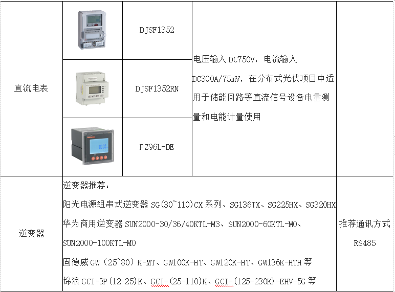
According to the design requirements, the inverter needs to provide remote control function, and when a fault occurs, it can output an alarm signal in time. Therefore, two types of inverters are selected, one is CS1 grid-connected photovoltaic inverter. This type of inverter has more communication interfaces and remote control functions, and has a wide input voltage range, making it suitable for small string low-voltage equipment. The other is the SUN2000-60KTL-M0 string inverter. This type of string inverter is based on a modular design, which can reduce the situation that the best working point of the battery component does not match the inverter, and greatly increase the power generation.
4. Software development
Use the Riyear-PowerNet system to design the industrial site information of the photovoltaic power station. The collected component data is stored in the RiyearPowerNet system, and a historical and real-time database is established. When a system failure occurs, the stored data is used to analyze and locate the failure.
4.1 Software structure
The intelligent hardware system is connected with the upper computer through the Modbus driver, and the man-machine interface can display the device data records, data alarms, etc. The system software structure is shown in Figure 2.

4.2 Software design and implementation
First, add configuration, choose two I/O configurations from Changshu Switchgear Manufacturing Co., Ltd.; second, in order to be able to read data, you need to define the database; third, define intermediate variables. Before defining the database variables, it is necessary to determine the equipment type and equipment module. The data is collected by Modbus standard commands and stored in various registers, which is convenient for the software to read the data. In the device configuration, set the device address, serial port number and related communication parameters according to the relevant requirements. The scope of database variables includes the entire application. To define the database is to define the address, and connect the variable with the corresponding device. At this time, when connecting, you can rely on the address set in advance to accurately find the desired data.
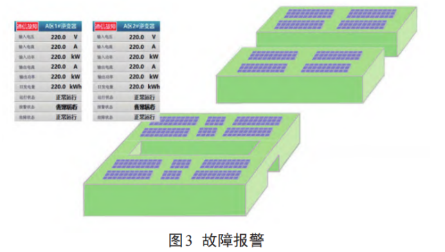
When a device fails and the software judges that a response is required, it will switch to the fault interface of the device in time and play an alarm sound at the same time. When the inverter fails, the display area on the main interface of the system flickers, so that the on-duty personnel can quickly locate the fault area. The system fault alarm display is shown in Figure 3.
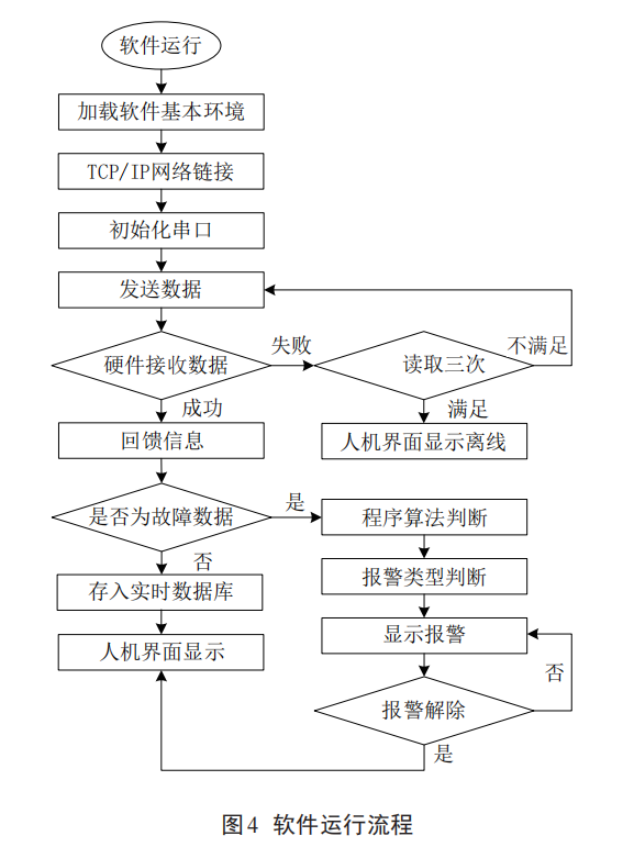
4.3 Software running process
First start the software, after the basic environment of the software is loaded, TCP/IP is connected to the network, after the connection is completed, each serial port is initialized, and data is sent to the hardware device according to the address. If the sending fails, then try to send three times in a row. If the sending is still unsuccessful, then it is judged that the device is offline; Real-time database, and read data on the man-machine interface. Connect each serial port to communicate with each other and load and read historical data. If the smart device fails, it will send fault data to the system. The system judges the fault type of the device according to the defined algorithm, displays the alarm area on the interface, and the software system returns to the normal state after the fault is resolved. The flowchart is shown in Figure 4.
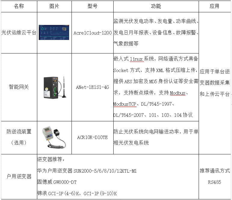
5. Introduction of Ankerui Distributed Photovoltaic Operation and Maintenance Cloud Platform


5.1 Overview
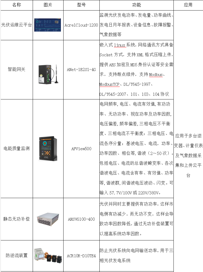
AcrelCloud-1200 distributed photovoltaic operation and maintenance cloud platform helps users manage scattered photovoltaic sites by monitoring inverter equipment, meteorological equipment and camera equipment of photovoltaic sites. The main functions include: site monitoring, inverter monitoring, power generation statistics, inverter primary diagram, operation log, alarm information, environmental monitoring, equipment files, operation and maintenance management, role management. Users can access the platform through WEB and APP to keep abreast of photovoltaic power generation efficiency and power generation revenue.
5.2 Application places
At present, the two distributed application scenarios in my country are: household photovoltaics on the roofs of vast rural areas and rooftop photovoltaics of industrial and commercial enterprises. Both types of distributed photovoltaic power stations have developed rapidly this year.
5.3 System structure
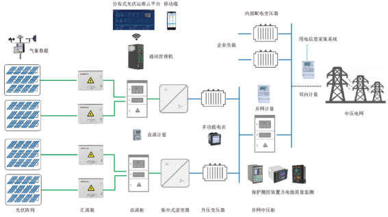
Install inverters and multi-functional power metering instruments in photovoltaic substations, upload the collected data to the server through the gateway, and centrally store and manage the data. Users can access the platform through a PC to obtain the operating status of the distributed photovoltaic power plant and the operating status of each inverter in a timely manner. The overall structure of the platform is shown in the figure.

5.4 System functions
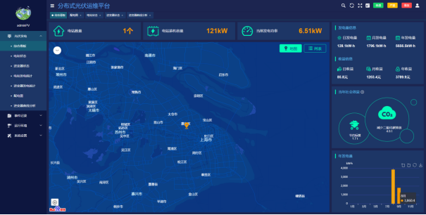
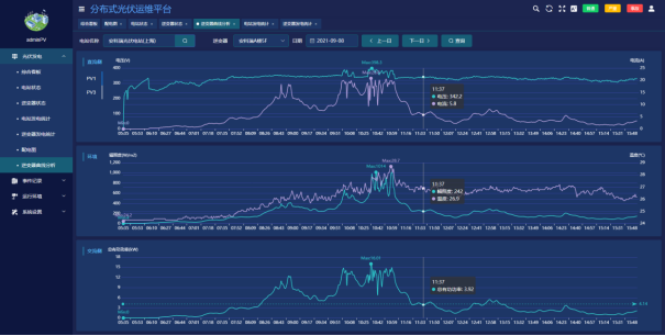
The AcrelCloud-1200 distributed photovoltaic operation and maintenance cloud platform software adopts the B/S architecture. Any authorized user can monitor the operating status of the photovoltaic power plants distributed in various buildings in the area through the WEB browser according to the scope of authority (such as the geographical distribution of the power station, Power station information, inverter status, power generation curve, grid connection, current power generation, total power generation, etc.).
5.4.1 Photovoltaic Power Generation
5.4.1.1 Comprehensive Kanban
●Display the quantity, installed capacity and real-time power generation of all photovoltaic power plants.
●Accumulated daily, monthly and annual power generation and power generation revenue.
●Cumulative social benefits.
●Histogram shows monthly power generation
5.4.1.2 Power Station Status
●The status of the power station displays basic parameters such as the power generation power of the current photovoltaic power station, subsidized electricity price, and peak power.
●Statistics of daily, monthly and annual power generation and power generation revenue of current photovoltaic power plants.
●The camera monitors the site environment in real time, and accesses environmental parameters such as irradiance, temperature and humidity, and wind speed.
●Display the number of connected inverters and basic parameters of the current photovoltaic power station.

5.4.1.3 Inverter Status
●Inverter basic parameter display.
●Daily, monthly, annual power generation and power generation income display.
●Display inverter power and environmental irradiance curves through graphs.
● DC side voltage and current query.
● AC voltage, current, active power, frequency, power factor query.

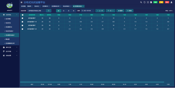
5.4.1.4 Power Generation Statistics of Power Stations
●Display the hourly, daily, monthly and annual power generation statistical report of the selected power station.

5.4.1.5 Inverter Power Generation Statistics
●Display the hourly, daily, monthly and annual power generation statistical report of the selected inverter
5.4.1.6 Distribution diagram
●Real-time display of inverter AC and DC side data.
●Display the number of components connected to the current inverter.
●Display the current irradiance, temperature and humidity, wind speed and other environmental parameters.
●Display inverter models and manufacturers.

5.4.1.7 Inverter Curve Analysis
●Display AC and DC side voltage, power, irradiance and temperature curves.
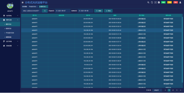
5.4.2 Event record
●Operation log: user login status query.
●SMS log: query the time, content, sending result, reply, etc. of SMS messages.
●Platform operation log: Check the offline status of meters and gateways.
●Alarm information: Classify the alarms, record the alarm content, occurrence time and confirmation status.
5.4.3 Operating environment
●Video monitoring: Through the video camera installed on site, the operation of the photovoltaic station can be monitored in real time. For cameras with hardware conditions, it also supports video playback and PTZ control functions.

5.5 System hardware configuration
5.5.1 AC 220V grid connection
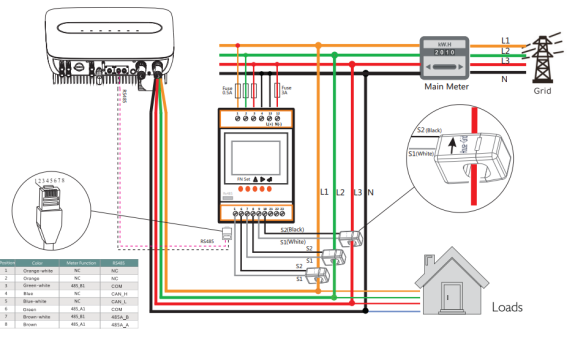
The AC 220V grid-connected photovoltaic power generation system is mostly used for residential rooftop photovoltaic power generation, with an installed power of about 8kW.

Some small photovoltaic power plants are self-contained, and the remaining power is not connected to the grid. This type of photovoltaic power plant needs to be installed with anti-backflow protection devices to avoid sending power to the grid. Photovoltaic power plants are small in scale and relatively scattered. For the managers of photovoltaic power plants, it is necessary to manage such photovoltaic power plants through the cloud platform. The solutions provided by Ankerui in such photovoltaic power plants include the following aspects:
5.5.2 AC 380V grid connection
According to the State Grid Q/GDW1480-2015 "Technical Regulations for Connecting Distributed Power to the Grid", 8kW~400kW can be connected to the grid at 380V, and photovoltaic power stations exceeding 400kW can also use multi-point 380V grid connection depending on the situation, subject to the approval opinions of the local power department prevail. This type of distributed photovoltaic is mostly rooftop photovoltaic of industrial and commercial enterprises, which is self-generated and used for self-use, and the surplus electricity is connected to the grid. Before distributed photovoltaics are connected to the distribution network, the metering point should be clearly defined. In addition to the property right demarcation point, the metering point setting should also consider the distributed power outlet and the user's own power line. Each metering point shall be equipped with a two-way electric energy metering device, and its equipment configuration and technical requirements shall comply with the relevant provisions of DL/T448, as well as the requirements of relevant standards and regulations. The electric energy meter adopts the smart electric energy meter, and the technical performance should meet the relevant standards of the State Grid Corporation of China on the intelligent electric energy meter. The distributed power metering device used for settlement and assessment should be equipped with collection equipment and connected to the electricity consumption information collection system to realize remote automatic collection of electricity consumption information.

The photovoltaic array is connected to the string photovoltaic inverter, or connected to the inverter through the combiner box, and then connected to the 380V power grid of the enterprise to realize self-generation and self-use, and the surplus electricity is connected to the grid. Metering meters need to be installed before the 380V grid connection point to measure photovoltaic power generation. At the same time, two-way metering meters are also required to be installed at the connection between the enterprise grid and the public grid to measure the enterprise’s on-grid electricity. The data should be uploaded to the power consumption information collection system of the power supply department. , used for photovoltaic power generation subsidies and on-grid electricity settlement.
Some grid-connected points of photovoltaic power plants need to monitor the power quality of the grid-connected point, including power frequency, power voltage, voltage unbalance, voltage swell/sag/interruption, rapid voltage change, harmonic/interharmonic THD, flicker, etc. A separate power quality monitoring device needs to be installed. Some photovoltaic power stations are self-contained, and the surplus power is not connected to the grid. This type of photovoltaic power station needs to be installed with an anti-backflow protection device to avoid sending electric energy to the grid. The system diagram is as follows.
This type of grid-connected single photovoltaic power station has a moderate scale, and can use the photovoltaic power generation data and energy storage system operation data through the cloud platform. The solutions provided by Ankerui in this type of photovoltaic power station include the following aspects:
5.5.310kV or 35kV grid connection
According to the "Notice of the National Energy Administration on Matters Concerning the Construction of Wind Power and Photovoltaic Power Generation Projects in 2019" (Guofa Xinneng [2019] No. 49), for new industrial and commercial distributed photovoltaic power generation projects that require state subsidies, they need to meet the requirements of single-point grid-connected installed capacity The requirement that the capacity is less than 6 MW and non-residential use supports access to the power distribution system through internal multi-points on the premise of meeting the technical requirements for grid operation safety.
This type of distributed photovoltaic installed capacity is generally relatively large, and it needs to be connected to the grid after being boosted by a step-up transformer. Due to the large installed capacity, it may cause relatively large interference to the public power grid. Therefore, the power supply department has relatively high requirements for the stability control system, power quality, and communication with dispatching of distributed photovoltaic power plants of this scale.
The grid-connected points of photovoltaic power stations need to monitor the power quality of the grid-connected points, including power frequency, power voltage, voltage unbalance, voltage swell/sag/interruption, rapid voltage change, harmonic/interharmonic THD, flicker, etc. Install a separate power quality monitoring device.
The above picture is a schematic diagram of a 1MW distributed photovoltaic power station. The photovoltaic array is connected to the photovoltaic combiner box, and then connected to the centralized inverter after confluence by the DC cabinet (the DC cabinet may not be installed according to the situation), and finally boosted to 10kV by the step-up transformer Or 35kV and then merged into the medium voltage grid. Due to the relatively large installed capacity of photovoltaic power plants, there are many protection and measurement and control equipment involved, mainly as follows:

5. Conclusion
Undoubtedly, equipment monitoring is of great significance to the safe operation and management of photovoltaic power plants. In order to facilitate the intelligent and refined management of the power station, this paper designs and develops an intelligent monitoring system for photovoltaic power stations. The system collects data from the equipment of the photovoltaic power station, and then uses the RS485 bus to transmit the data to the host computer; then, uses the RiyearPowerNet software to build the historical and real-time operating data of the power station into a database. Based on this, the software realizes real-time and online monitoring of the power station. When a photovoltaic device fails, the monitoring system can quickly and accurately locate the fault location by analyzing the database data. The monitoring system ensures the reliable operation and centralized management of photovoltaic power plants.