I. Overview
Whether you are a novice or a master, based on the development of STM32 single-chip microcomputer, using STM32CubeMX can greatly improve the development efficiency, and its interface development also greatly reduces the development threshold for novices on STM32 single-chip microcomputer.
This article mainly describes the configuration and related knowledge of the Uart of the STM32 chip. Because of its concise protocol and convenient use, Uart can be regarded as the most frequently seen peripheral in the single-chip microcomputer, except for the GPIO peripheral. Next, let's take a look at how to use STM32CubeMX to get a first glimpse.
2. Software description
STM32CubeMX is an official ST MCU/MPU cross-platform graphical tool for ST. It supports development under Linux, MacOS, and Window systems. Its underlying interface is the HAL library. In addition, students who are accustomed to register development, LL libraries can also be used. In addition to integrating the hardware abstraction layer of MCU/MPU, STM32CubeMX also integrates middleware such as RTOS, file system, USB, network, display, embedded AI, etc., so that developers can easily complete the underlying driver of MCU/MPU Configuration, leaving more energy to develop upper-layer functional logic, can further improve the efficiency of embedded development.
Demo version 6.7.0
3. Introduction to Uart
Universal Asynchronous Receiver/Transmitter (Universal Asynchronous Receiver/Transmitter), usually called UART, its specific protocol and content are described in detail in another article of mine, so I won't go into details here. Here we mainly talk about the characteristics of Uart in STM32. Now let's take the Uart of the G0 series as an example (the Uart of the STM32 series of single-chip microcomputers is similar, mastering one is equivalent to knowing everything), and check the manual to find the corresponding block diagram. Here we focus on the sending and receiving parts and some general-purpose registers.
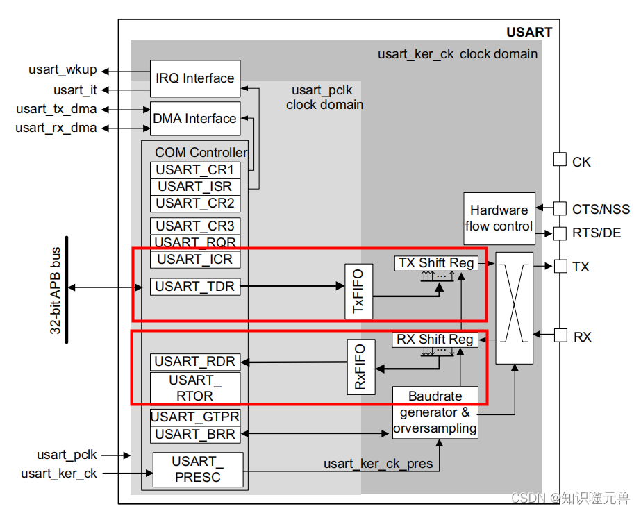
- Transmit (TDR, TxFIFO, Tx Shift Reg)
TDR: Send data register, because it is in COM Controller, we can directly operate it. After the Uart is initialized, as long as one byte of data is filled into this register, the hardware will automatically send this data out.
TxFIFO: Send queue. When the send queue function is turned on, when data is filled into TDR, the hardware will move the data in TDR to TxFIFO.
Tx Shift Reg: Transmit shift register. When the TxFIFO function is not enabled, if there is data in the TDR, the data will be copied to the transmit shift register first, and then sent out byte by byte according to the set baud rate.
Complete sending process (without FIFO)
1. Check whether the current TXE flag is 1. If it is 1, it means that the current TDR is empty and can be filled with data.
2. The TXE (send register is empty) flag is 1, and one byte of data is written to the TDR. At this time, the hardware will clear the TXE flag to 0.
3. If the Tx Shift Reg is empty at this time, the hardware will copy the data in the TDR to the Tx Shift Reg, and set the TXE flag to 1; otherwise, wait until the Tx Shift Reg is empty and then copy.
4. According to the configured baud rate, data bits, stop bits, and parity bits, the hardware packs the data into the form of the Uart protocol, and sends out bit by bit (first send the high bit, then send the low bit).
5. When Tx Shift Reg has sent the last stop bit, the hardware will set the TC (transmission complete) flag to 1.

- Receive (RDR, RxFIFO, Rx Shift Reg)
RDR: Receive data register, because it is in the COM Controller, we can directly read it.
RxFIFO: Receive queue. When the send queue function is turned on, when filling data into TDR, the hardware will move the data in TDR to TxFIFO.
Rx Shift Reg: Receive shift register, when the external data conforming to the Uart protocol comes, the Rx Shift Reg will receive the data bit by bit according to the current serial port configuration. After receiving a complete byte of data (including start bit, stop bit, etc.), the data part will be copied to RDR.
Complete receiving process (no FIFO)
1. Rx Shift Reg receives data bit by bit according to the configuration of the current baud rate, data bit, stop bit, and parity bit.
2. When receiving a complete byte of data (including start bit, stop bit, etc.), the hardware will copy the data part (excluding start, stop, and check bits) to RDR, and set the RXNE flag to 1.
3. When the current RXNE (receiving register is not empty) flag is 1, read the RDR data. When reading the RDR data, the hardware will clear the RXNE flag to 0.

4. Function configuration
1. Find the USART (some are UART) in the "Connectivity" option, and select "Asynchronous" in the mode configuration box on the right, which means asynchronous, that is, only need to receive and send two communication lines. If you select "Synchronous "It is a synchronous serial port, which requires an additional clock line. I won’t talk much about the others, but mainly look at the most commonly used two-wire asynchronous serial port configuration.

2. Configure the basic functions of the serial port, the normal default configuration is enough, and generally just change the baud rate.
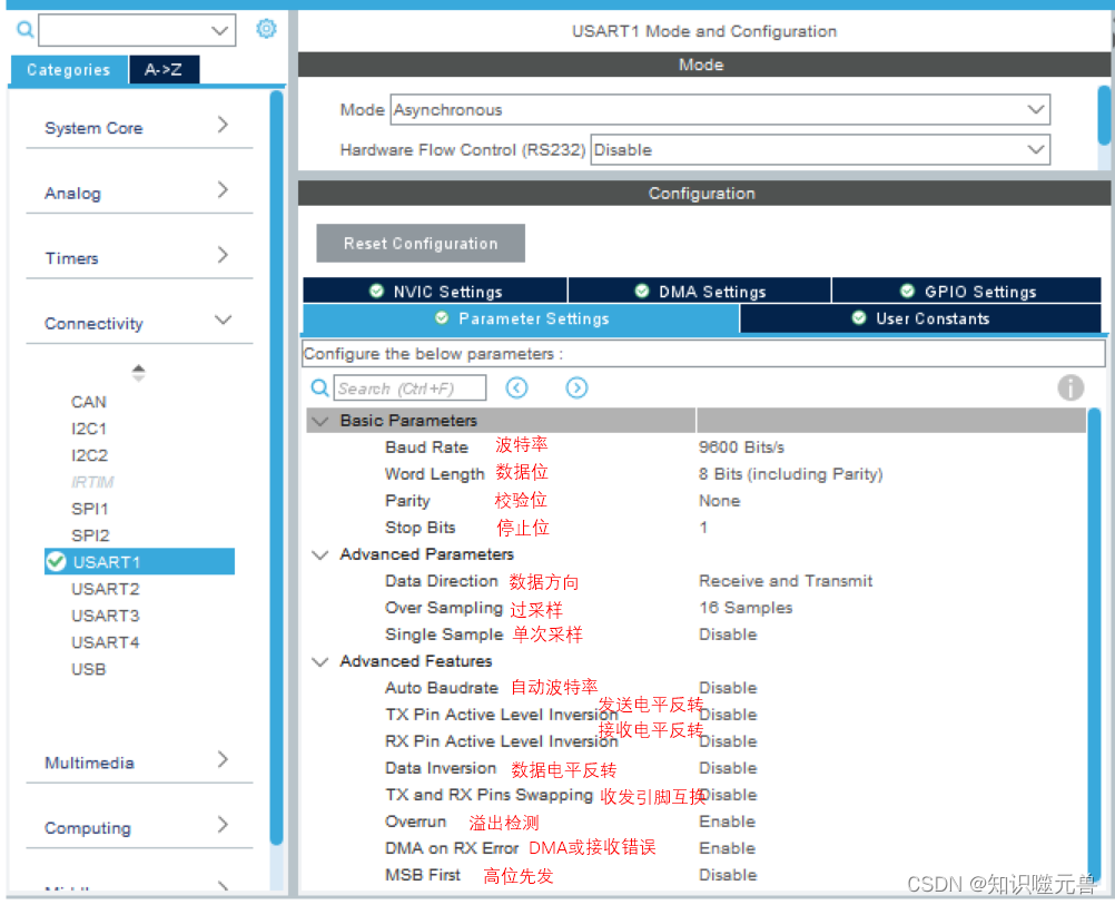
Baud Rate : Communication rate, commonly used is 9600, which means that 9600 bits are transmitted in 1s.
Data bits (Word Length) : The number of data bits carried in a byte, usually 8 bits, and ASCII can only use 7 bits.
Parity : parity check, used to check whether the transmitted data is wrong, generally configured as no parity.
Stop Bits : The number of stop bits at the end of the serial port protocol, generally configured as 1 stop bit.
Data Direction : Generally, both sending and receiving are required, so Receive and Transmit are configured here.
Oversampling (Over Sampling) : There are two types of 8-fold sampling and 16-fold sampling. 8-fold sampling means that a data bit is sampled 8 times, and 16 times is 16 times. The high precision of the sampling rate will be higher, and of course the corresponding power consumption will also be higher.
Single Sample : Use single sample value when enabled, otherwise use triple sample value. The previous oversampling will have 8 or 16 sampling values. When single sampling is selected, one of the sampling values will be used as the result of the logic level of the data bit. For three-time sampling, the judgment result of three-time sampling shall prevail. The same three sampling is also to ensure the accuracy of the data.
Auto Baudrate : As the name suggests, the baud rate can be adapted according to the received data, that is, a serial port with a 115200 baud rate is used to send data to the current serial port, and the serial port can recognize the baud rate and adjust it Its own baud rate corresponds to it. However, there is a prerequisite for using this function, that is, the data of the first byte must be specified. There are several data options such as 01. The accuracy of self-adaptation is different under different data and different baud rates. For details, see The manual has detailed instructions.
TX Pin Active Level Inversion (TX Pin Active Level Inversion) : The polarity of the transmit pin level is reversed. Under normal circumstances, the idle level is high. After enabling this function, the idle level becomes low.
RX Pin Active Level Inversion (RX Pin Active Level Inversion) : The polarity of the receive pin level is reversed. Under normal circumstances, the idle level is high. After enabling this function, the idle level becomes low.
Data Inversion (Data Inversion) : The polarity of the logic level of sending and receiving data is reversed. Normally, the high level is logic 1, and the low level is logic 0. After enabling this function, it becomes logic low. 1, high level is logic 0. The check digit is also inverted.
TX and RX Pins Swapping (TX and RX Pins Swapping) : The receiving and sending pins are swapped, which is suitable for switching when the external hardware connection is wrong.
Overrun detection (Overrun) : It is used to enable receive overflow detection. After using this function, when the received data is not fetched, another data is received, and an overflow flag will be triggered at this time.
Do not disable DMA when receiving errors (DMA on RX Error) : After enabling this function, DMA transmission will not be turned off even if a receiving error occurs.
Data MSB First (MSB First) : Normal data is to send the low order first and then the high order. After enabling this function, the high order data can be sent first.
3. Select the corresponding port. After enabling the serial port function, the tool will configure a pair of transceiver pins by default. It is best to confirm whether it is the pair of serial ports according to your own board. If not, you need to manually modify the port.

PA9 and PA10 correspond to the D8 and D2 ports on the development board.

4. If you need to use interrupts for sending and receiving, click "NVIC Setting" to enable the corresponding interrupts.

5. In the "Project Manager" interface, select "Advanced Setting", find USART, and select the corresponding generated library. The serial port can choose to generate HAL library or LL library. Finally, click "GENERATE CODE" to generate the project code to complete the configuration.

5. Function realization
After configuring the generated project above, the initialization of the serial port has been realized. Next, to implement the functional logic, the corresponding interface needs to be called.
- Blocking transceiver-HAL library
Focus on the two functions HAL_UART_Transmit and HAL_UART_Receive. Both are blocking interfaces, that is, when the sending interface is called, it needs to wait until all the data is sent before exiting this interface, and the receiving is to query the received data until the data receiving is completed or timeout. If there is a need to send and receive at the same time, you can call the HAL_USART_TransmitReceive interface.
uint8_t RecvData[100];
/* 收到数据回显 */
if (HAL_OK == HAL_UART_Receive(&huart1, RecvData, 9, 1000))
{


    HAL_UART_Transmit(&huart1, RecvData, 9, 1000);
}
Use the serial port debugging assistant to test the effect, send "abcdefg\r\n", and it will reply "abcdefg\r\n".

This interface is actually quite tasteless, because the interface does not give you feedback on the number of bytes received, so there is an embarrassing situation. Only when the number of bytes you receive is exactly the number of bytes you passed in, the interface Only then will it return the OK status to you, otherwise, under normal circumstances, it will return Timeout.
- Blocking transceiver-LL library
First, change the serial port generation library to LL library in the project configuration.

Imitate the implementation of the HAL library, and implement a simple version of the sending and receiving interface. First sort out the basic flow of the transceiver interface (omitting protection-related operations).
- The sending process of the sending interface

- The receiving process of the receiving interface

Use the LL library to imitate the implementation of the HAL library. Here we slightly modify the receiving interface and return the number of bytes received.
/*******************************************************************************
*  函数名称      :   uint8_t Uart_Send(void *pt,
*  描     述   :   发送函数
*  输     入   :   void *pt,          // 结构块实体
                   uint8_t *data,     // 发送的数据缓存
                   uint32_t len,      // 发送的数据长度
                   uint32_t timeout   // 超时时间
*  返     回   :   1-成功 0-失败
*  作     者   :   Chewie
*  时     间   :   2023.03.20  22:28:21
*******************************************************************************/
uint8_t Uart_Send(void *pt,
                    uint8_t *data,
                    uint32_t len,
                    uint32_t timeout)
{


    uint32_t i = 0;

    /* 获取当前计数值,用于计算超时时间 */
    uint32_t tickstart = HAL_GetTick();

    /* 按需要发送的字节数循环发送 */
    while (len--)
    {


        /* 超时时间到,则认为发送失败 */
        if ((HAL_GetTick() - tickstart) >= timeout)
        {


            return 0;
        }
        /* 当TXE寄存器为1时,可以往发送寄存器里填值 */
        while (!LL_USART_IsActiveFlag_TXE((USART_TypeDef *)pt))
        {


            /* 超时时间到,则认为发送失败 */
            if ((HAL_GetTick() - tickstart) >= timeout)
            {


                return 0;
            }
        }
        LL_USART_TransmitData8((USART_TypeDef *)pt, data[i++]);
    }
    /* 获取当前计数值,用于计算超时时间 */
    tickstart = HAL_GetTick();

    /* 等待发送完成--TC标志位为1 */
    while (!LL_USART_IsActiveFlag_TC((USART_TypeDef *)pt))
    {


        /* 超时时间到,则认为发送失败 */
        if ((HAL_GetTick() - tickstart) >= timeout)
        {


            return 0;
        }
    }

    return 1;
}

/*******************************************************************************
*  函数名称      :   uint8_t Uart_Recv(void *pt,
*  描     述   :   接收函数
*  输     入   :   void *pt,          // 结构块实体
                   uint8_t *data,     // 接收的数据缓存
                   uint32_t max_len,	// 可接收的最大字节数
                   uint32_t *len,     // 接收的数据长度
                   uint32_t timeout   // 超时时间
*  返     回   :   1-成功 0-失败
*  作     者   :   Chewie
*  时     间   :   2023.03.20  22:33:26
*******************************************************************************/
uint8_t Uart_Recv(void *pt,
                    uint8_t *data,
                    uint32_t max_len,
                    uint32_t *len,
                    uint32_t timeout)
{


    *len = 0;

    /* 获取当前计数值,用于计算超时时间 */
    uint32_t tickstart = HAL_GetTick();

    /* 按需要发送的字节数循环发送 */
    while (max_len--)
    {


        /* 超时时间到,则认为发送失败 */
        if ((HAL_GetTick() - tickstart) >= timeout)
        {


            return 0;
        }
        /* 当RXNE寄存器为1时,可以获取接收寄存器里的值 */
        while (!LL_USART_IsActiveFlag_RXNE((USART_TypeDef *)pt))
        {


            /* 超时时间到,则认为发送失败 */
            if ((HAL_GetTick() - tickstart) >= timeout)
            {


                return 0;
            }
        }
        data[(*len)++] = LL_USART_ReceiveData8((USART_TypeDef *)pt);
    }

    return 1;
}

/* 应用代码 */
int main()
{


	uint8_t RecvData[255];
	uint32_t recv_len = 0;
	...
	while (1)
	{


		/* 收到数据回显 */
		Uart_Recv(USART1, RecvData, sizeof(RecvData), &recv_len, 1000);
		if (0 != recv_len)
		{


		    Uart_Send(USART1, RecvData, recv_len, 1000);
		}
	}
}
Such a transceiver interface can basically meet basic applications.

Receiving uses the query method to receive data, which is easy to leak data. And in the case of bare metal, if you use this interface to send data, you need to wait here and cannot perform other tasks. If there are multiple serial ports blocked, the situation will be more serious. So is there any way to improve the real-time performance of communication without affecting the operation of other tasks? In addition to using the operating system, you can also borrow a very important function of the microcontroller itself - interrupt. Let's take a look at how the interrupt is implemented.
- Interrupt transceiver-HAL library
Here we use two other read and write interfaces of the HAL library, HAL_UART_Transmit_IT and HAL_UART_Receive_IT. You only need to call these two interfaces, and the interrupt will help us perform the rest of the sending and receiving work. In order to know the status of receiving and sending in real time, we need to enable the callback function registration function, so we have to use another callback function registration interface HAL_UART_RegisterCallback.
First enable the serial port interrupt first, and then enable the callback registration of the serial port (theoretically, if the USART is used here, the USART is turned on, and if the UART is used, the UART is turned on).

Likewise, implement a simple string echo function.
/* 发送完成回调,发送完就启动接收 */
void UartTxCallback(UART_HandleTypeDef *huart1)
{


    HAL_UART_Receive_IT(huart1, RecvData, 9);
}

/* 接收完成回调,接收完就启动发送 */
void UartRxCallback(UART_HandleTypeDef *huart1)
{


    HAL_UART_Transmit_IT(huart1, RecvData, 9);
}

int main(void)
{


	/* 初始化部分省略 */
	......

	/* 注册发送完成回调函数 */
	HAL_UART_RegisterCallback(&huart1, HAL_UART_TX_COMPLETE_CB_ID, UartTxCallback);
	/* 注册接收完成回调函数 */
	HAL_UART_RegisterCallback(&huart1, HAL_UART_RX_COMPLETE_CB_ID, UartRxCallback);

	/* 接收启动 */
	HAL_UART_Receive_IT(&huart1, RecvData, 9);
	while (1)
	{


		......
	}
}

The problem is the same as the previous non-interrupt interface. The receiving interface here does not feedback the number of bytes received, so the current writing method must be to know how many bytes to receive, and set the number of bytes to receive. For variable length data cannot be processed.
- Interrupt transceiver-LL library
For the implementation of the LL library, we follow the gourd to imitate the implementation of the HAL library. First draw the basic flowchart of HAL implementation.
- The sending process of the sending interface

-
The receiving process of the receiving interface

-
interrupt the flow of execution

The LL library is used to imitate the implementation of the HAL library. Similarly, the receiving callback interface is modified so that when the receiving callback is completed, the number of bytes received is returned. Because the data is now received with an indefinite length, it is necessary to change the judgment mechanism of the completion of reception from the original judgment of the number of bytes to the time-out judgment.
struct tagUartRxTxCB
{


    USART_TypeDef *Uart;
    uint8_t *Data;
    uint32_t RxMaxLen;
    uint32_t RxCnt;
    uint32_t StartRx;
    uint32_t Timeout;
    uint32_t TxLen;
    uint32_t TxCnt;
    uint32_t TimeoutCnt;

    void (*RxCallback)(void *);
    void (*TxCallback)(void *);
};

/* 实例化 */
struct tagUartRxTxCB UartCB =
{


    .Uart = USART1,
};

/* 回调类型 */
enum emUartRegCallbackType
{


    UART_REGCB_TYPE_rx_complete = 0,
    UART_REGCB_TYPE_tx_complete = 1,
};


/*******************************************************************************
*  函数名称      :   void Uart_RegisterCallback(void *pt,
*  描     述   :   注册回调函数
*  输     入   :   void *pt,                          // 模块结构块
                 enum emUartRegCallbackType type,   // 回调类型
                 void (*callback)(void *)           // 回调函数
*  返     回   :   无
*  作     者   :   Chewie
*  时     间   :   2023.05.01  23:52:49
*******************************************************************************/
void Uart_RegisterCallback(void *pt,
                                    enum emUartRegCallbackType type,
                                    void (*callback)(void *))
{


    struct tagUartRxTxCB *cb = (struct tagUartRxTxCB *)pt;

    switch (type)
    {


        case UART_REGCB_TYPE_rx_complete:
        {


            cb->RxCallback = callback;
            break;
        }
        case UART_REGCB_TYPE_tx_complete:
        {


            cb->TxCallback = callback;
            break;
        }
        default:
            break;
    }
}


/*******************************************************************************
*  函数名称      :   void Uart_RecvStart(void *pt,
*  描     述   :   开始接收
*  输     入   :   void *pt,              // 模块结构块
                 uint8_t *data,         // 接收的数据缓存
                 uint32_t max_len,      // 一次接收的最大字节数
                 uint32_t timeout       // 接收超时时间
*  返     回   :   无
*  作     者   :   Chewie
*  时     间   :   2023.05.01  23:53:55
*******************************************************************************/
void Uart_RecvStart(void *pt,
                            uint8_t *data,
                            uint32_t max_len,
                            uint32_t timeout)
{


    struct tagUartRxTxCB *cb = (struct tagUartRxTxCB *)pt;

    /* 记录需要接收的最大字节数 */
    cb->RxMaxLen = max_len;
    cb->Data = data;

    /* 记录超时时间 */
    cb->Timeout = timeout;

    /* 清空计数 */
    cb->RxCnt = 0;

    /* 使能接收中断 */
    LL_USART_EnableIT_RXNE(cb->Uart);
}

/*******************************************************************************
*  函数名称      :   void Uart_SendStart(void *pt,
*  描     述   :   开始发送
*  输     入   :   void *pt,              // 模块结构块
                 uint8_t *data,         // 发送数据缓存
                 uint32_t send_len      // 发送数据字节数
*  返     回   :   无
*  作     者   :   Chewie
*  时     间   :   2023.05.01  23:55:16
*******************************************************************************/
void Uart_SendStart(void *pt,
                            uint8_t *data,
                            uint32_t send_len)
{


    struct tagUartRxTxCB *cb = (struct tagUartRxTxCB *)pt;

    /* 记录需要发送的数据字节数 */
    cb->TxLen = send_len;

    /* 清空计数 */
    cb->TxCnt = 0;

    /* 使能TXEIE */
    LL_USART_EnableIT_TXE(cb->Uart);

    /* 使能TCIE--使能前要清一次TC,主要是第一次使能Uart时会产生一个TC */
    LL_USART_ClearFlag_TC(cb->Uart);
    LL_USART_EnableIT_TC(cb->Uart);
}

/*******************************************************************************
*  函数名称      :   void UartRxIrq(void *pt)
*  描     述   :   接收中断处理函数
*  输     入   :   模块结构块
*  返     回   :   无
*  作     者   :   Chewie
*  时     间   :   2023.05.01  23:56:26
*******************************************************************************/
void UartRxIrq(void *pt)
{


    struct tagUartRxTxCB *cb = (struct tagUartRxTxCB *)pt;

    /* 进一次RXNE中断接收一次数据 */
    if (   (LL_USART_IsEnabledIT_RXNE(cb->Uart))
        && (LL_USART_IsActiveFlag_RXNE(cb->Uart))
        )
    {


        /* 刷新接收超时时间 */
        cb->TimeoutCnt = HAL_GetTick();

        /* 超时时间有效 */
        cb->StartRx = 1;

        /* 接收数据 */
        cb->Data[cb->RxCnt++] = LL_USART_ReceiveData8(cb->Uart);

        /* 接收满对应字节数,则回调接收完成函数 */
        if (cb->RxCnt == cb->RxMaxLen)
        {


            cb->RxCallback(cb);
            cb->StartRx = 0;
        }
    }
}

/*******************************************************************************
*  函数名称      :   void UartTxIrq(void *pt)
*  描     述   :   发送中断处理函数
*  输     入   :   模块结构块
*  返     回   :   无
*  作     者   :   Chewie
*  时     间   :   2023.05.01  23:56:49
*******************************************************************************/
void UartTxIrq(void *pt)
{


    struct tagUartRxTxCB *cb = (struct tagUartRxTxCB *)pt;

    /* TC为1时触发的中断,则重新启动接收 */
    if (   (LL_USART_IsEnabledIT_TC(cb->Uart))
        && (LL_USART_IsActiveFlag_TC(cb->Uart))
        )
    {


        /* 清除标志 */
        LL_USART_ClearFlag_TC(cb->Uart);

        /* 发送完成回调 */
        cb->TxCallback(cb);
        return ;
    }

    /* TXE为1时触发的中断,则发送数据 */
    if (   (LL_USART_IsEnabledIT_TXE(cb->Uart))
        && (LL_USART_IsActiveFlag_TXE(cb->Uart))
        )
    {


        LL_USART_TransmitData8(cb->Uart, cb->Data[cb->TxCnt++]);
    }

    /* 剩余发送字节数为0,则说明发送完,关闭TXEIE防止再次进TXE中断 */
    if (cb->TxCnt == cb->TxLen)
    {


        /* 禁止TXEIE */
        LL_USART_DisableIT_TXE(cb->Uart);
    }
}

/*******************************************************************************
*  函数名称      :   void UartTxCallback(void *pt)
*  描     述   :   发送完成回调函数
*  输     入   :   模块结构块
*  返     回   :   无
*  作     者   :   Chewie
*  时     间   :   2023.05.01  23:57:09
*******************************************************************************/
void UartTxCallback(void *pt)
{


    Uart_RecvStart(pt, RecvData, sizeof(RecvData), 5);
}

/*******************************************************************************
*  函数名称      :   void UartRxCallback(void *pt)
*  描     述   :   接收完成回调函数
*  输     入   :   模块结构块
*  返     回   :   无
*  作     者   :   Chewie
*  时     间   :   2023.05.01  23:57:23
*******************************************************************************/
void UartRxCallback(void *pt)
{


    struct tagUartRxTxCB *cb = (struct tagUartRxTxCB *)pt;

    Uart_SendStart(pt, RecvData, cb->RxCnt);
}

int main(void)
{


    ......
	Uart_RegisterCallback(&UartCB, UART_REGCB_TYPE_rx_complete, UartRxCallback);
    Uart_RegisterCallback(&UartCB, UART_REGCB_TYPE_tx_complete, UartTxCallback);
    Uart_RecvStart(&UartCB, RecvData, sizeof(RecvData), 5);
    while (1)
    {


		/* 超时时间到,则认为接收完成 */
        if (   ((HAL_GetTick() - UartCB.TimeoutCnt) >= UartCB.Timeout)
            && (UartCB.StartRx == 1)
            )
        {


            UartCB.StartRx = 0;
            UartCB.RxCallback(&UartCB);
        }
	}
}

/***********************stm32f0xx_it.c**************************/
void USART1_IRQHandler(void)
{


  /* USER CODE BEGIN USART1_IRQn 0 */
  UartRxIrq(&UartCB);
  UartTxIrq(&UartCB);

  /* USER CODE END USART1_IRQn 0 */
  /* USER CODE BEGIN USART1_IRQn 1 */

  /* USER CODE END USART1_IRQn 1 */
}
At present, this implementation method is used in the scenario of one receiving and one sending. If full-duplex sending and receiving is required, then you need to infer other cases by yourself. In fact, the current sending and receiving process of this form still requires the intervention of the kernel. Is there a way to reduce the intervention time of the kernel? Of course there is, this is DMA. The use of DMA involves other configurations, so let’s leave a hole here first, and then elaborate on the configuration of Uart+DMA in the DMA chapter.
6. Matters needing attention
1. If the RS485 interface is used externally, you need to pay attention to the conversion timing of the sending and receiving pins. Generally, it is in the receiving state. Only switch to the sending state before sending, and switch to the receiving state after sending (at least after triggering the TC flag) switch again, otherwise data will be lost). There cannot be two or more devices in the sending state on the 485 bus at the same time, otherwise the bus level will be pulled down and data cannot be received normally.
2. When the main frequency of the MCU is high, the number of baud rate settings may not be enough when configuring a low baud rate (most registers for setting the baud rate are only 16 bits), the formula in the application manual uses the clock frequency of the serial port The value after /baud rate may exceed the range that can be set by its register. At this time, you can set a lower baud rate by dividing the frequency of the serial port. If you use STM32CubeMX for configuration, the tool will automatically limit the minimum baud rate, and the setting interface using the HAL library will also be limited. You must pay attention to the setting interface implemented by the LL library.
3. The data bits set in the ST serial port include parity bits. For example, if the data bits are set to 8 bits and the parity check is set, the actual effective data is only 7 bits, and the remaining one bit is occupied by the parity check bit. For tools like Modbus Poll, the set data bits do not include a parity bit.