Article directory
1. Button control
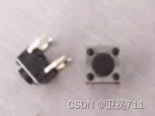
1.1 Know the keys
- Purpose: To control the operation of motors or other electrical equipment, commonly used
连通或断开to control circuits
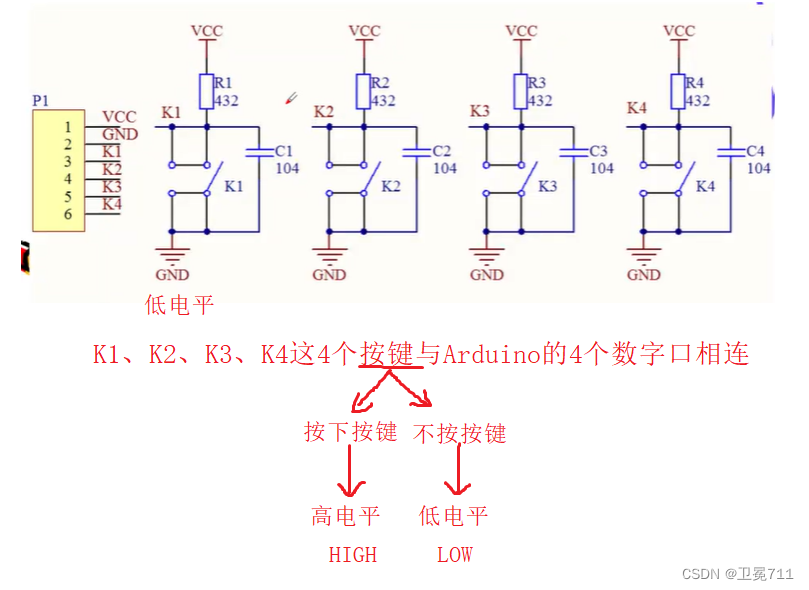
1.2 Working principle
- Principle: K1, K2, K3, K4 [switches] are connected to digital pins, and displayed as level levels by operating the keys
- In the case of not pressing, K1 is connected to R1 and connected to VCC, showing a high level
- When the key is pressed, K1 is directly connected to GND, showing a low level
1.3 Arduino code display
//定义按键
int k1 = 8;
int k2 = 9;
int k3 = 10;
int k4 = 11;

void setup(){


	Serial.begin(9600);
	pinMode(k1, INPUT);
	pinMode(k2, INPUT);
	pinMode(k3, INPUT);
	pinMode(k4, INPUT);
}

void loop(){


	if(!digitalRead(k1))	//按下k1,digitalRead返回值为低电平【即返回为0】,取反为1,打印出“k1被按下”
		Serial.println("K1 is pressed");
	if(!digitalRead(k2))
		Serial.println("K2 is pressed");
	if(!digitalRead(k3))
		Serial.println("K3 is pressed");
	if(!digitalRead(k4))
		Serial.println("K4 is pressed");
	delay(100);
}
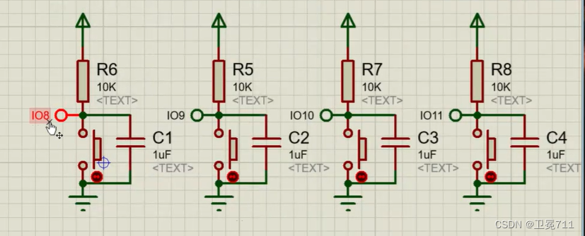
1.4 Schematic
- When k1 is pressed, see what the window monitor outputs
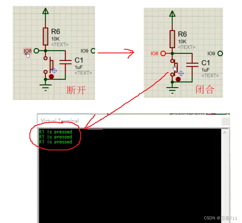
- The reason for the output of 3 "K1 is pressed" is the jitter of the program
1.5 Realize debounce [debounce delay]
int k1 = 8, k2 = 9, k3 = 10, k4 = 11; //定义按键
int key = 0; //定义键值
int key1 = 0;

void setup(){


	Serial.begin(9600);
	pinMode(k1, INPUT_PULLUP);
	pinMode(k2, INPUT_PULLUP);
	pinMode(k3, INPUT_PULLUP);
	pinMode(k4, INPUT_PULLUP);
}

void read_key(){


	if(!digitalRead(k1) || !digitalRead(k2) || !digitalRead(k3) || !digitalRead(k4)){

     //同时读取4个按键值,只要有一个按键被按下,则显示为低电平,取反之后为1,条件为真,执行程序
		delay(25); //消抖动延时
		if(!digitalRead(k1) || !digitalRead(k2) || !digitalRead(k3) || !digitalRead(k4)){

     //再次读取键值,确认是否有按键
			if(!digitalRead(k1)) key = 1; //记录按下的键值
			if(!digitalRead(k2)) key = 2;
			if(!digitalRead(k3)) key = 3;
			if(!digitalRead(k4)) key = 4;
		}
		else key = 0;
	}
	if(key1 != key) //只要这个键一直按着不松开,则认为按一个键。屏蔽标准键盘输入的联机问题,不会认为按许多键
		key1 = key;
	else
		key = 0;
}

void loop(){

     //主函数,先查询有无按键,有按键的话在屏幕显示结果
	read_key(); //调用读取按键的函数
	if(!key){


		Serial.print("K");
		Serial.print(key);
		Serial.println(" is pressed");
		key = 0; //再初始化为0,方面下次循环
	}
}
2. Buzzer control
2.1 Know the buzzer
- The buzzer is an electronic sounder with an integrated structure, which is powered by DC voltage and is mainly used as a generating device in electronic products.

2.2 Classification
- by structure
- piezoelectric buzzer
- Electromagnetic buzzer
- According to whether there is an oscillation source
- active buzzer
- passive buzzer
a is an active buzzer, b is a passive buzzer
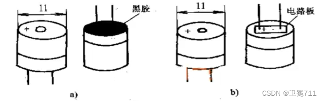
2.3 Working principle
- active buzzer
- The active buzzer contains an oscillating circuit inside, mainly through the supply of direct current, which will be
恒定直流电converted into一定频率的脉冲信号, so as to realize the alternating magnetic field and drive the molybdenum plate to vibrate and sound.
- passive buzzer
- There is no vibration source inside, so when DC is applied, the magnetic circuit is constant, and the molybdenum sheet cannot vibrate and make sound. Only
方波the ideal signal is added, the frequency is different, and the sound produced by the vibration is also different.
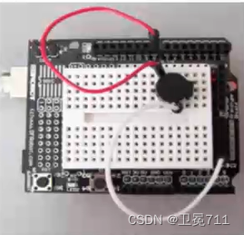
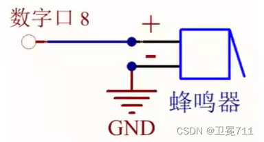
2.4 Connection
- The buzzer is connected to two wires, the positive pole is connected to the digital 8 port, and the negative pole is connected to the GND socket.
2.5 Arduino code display
int buzzer = 8; //定义控制蜂鸣器的数字IO脚,另一脚连接到GND上

void setup(){


	pinMode(buzzer, OUTPUT); //设置数字IO模式,OUTPUT为输出
	//Arduino输送信号控制蜂鸣器响不响,所以定义为OUTPUT
}

void loop(){


	unsigned char i, j; //定义变量
	while(1){


		for(i = 0; i < 80; i ++){

     //输出一个频率的声音
			digitalWrite(buzzer, HIGH); //发声音
			delay(1); //延迟1ms
			digitalWrite(buzzer, LOW); //不发声音
			delay(1); //延迟1ms
		}
		for(i = 0; i < 100; i ++){

     //输出另一个频率的声音
			digitalWrite(buzzer, HIGH);
			delay(2); //延迟2ms
			digitalWrite(buzzer, LOW);
			delay(2);
		}
	}
}
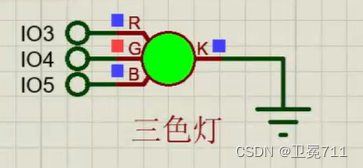
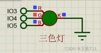
3. PWM analog output
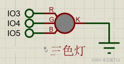
The three-color lamp whose brightness changes gradually——"breathing lamp" realizes the change of lamp
3.2 Arduino code display
const int red = 3;
const int green = 4;
const int blue = 5;
//3、4、5属于PWM引脚

void setup(){


	set pins 2 through 13 as outputs:
	{


		pinMode(red, OUTPUT);
		pinMode(green, OUTPUT);
		pinMode(blue, OUTPUT);
	}
}

void loop(){


	//低--->高变化【白色形成】
	for(int brightness = 0; brightness < 255; brightness ++){

     //0 ~ 255,红绿蓝同步逐渐发生变化
		analogWrite(red, brightness);
		analogWrite(green, brightness);
		analogWrite(blue, brightness);
		delay(3);
	}

	//高--->低变化【白色褪色】
	for(int brightness = 255; brightness >= 0; brightness --){


		analogWrite(red, brightness);
		analogWrite(green, brightness);
		analogWrite(blue, brightness);
		delay(3);
	}

	//显示红色
	for(int brightness = 255; brightness >= 0; brightness --){


		analogWrite(red, brightness);
		//analogWrite(green, brightness);
		//analogWrite(blue, brightness);
		delay(3);
	}

	//显示绿色
	for(int brightness = 255; brightness >= 0; brightness --){


		//analogWrite(red, brightness);
		analogWrite(green, brightness);
		//analogWrite(blue, brightness);
		delay(3);
	}

	//显示蓝色
	for(int brightness = 255; brightness >= 0; brightness --){


		//analogWrite(red, brightness);
		//analogWrite(green, brightness);
		analogWrite(blue, brightness);
		delay(3);
	}

	//显示红绿的混色
	for(int brightness = 255; brightness >= 0; brightness --){


		analogWrite(red, brightness);
		analogWrite(green, brightness);
		//analogWrite(blue, brightness);
		delay(3);
	}

	//显示红蓝混色
	for(int brightness = 255; brightness >= 0; brightness --){


		analogWrite(red, brightness);
		//analogWrite(green, brightness);
		analogWrite(blue, brightness);
		delay(3);
	}

	//显示绿蓝混色
	for(int brightness = 255; brightness >= 0; brightness --){


		//analogWrite(red, brightness);
		analogWrite(green, brightness);
		analogWrite(blue, brightness);
		delay(3);
	}
}
4. Wet temperature measurement
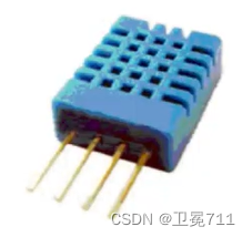
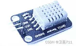
4.1 Know the device
- It is used to roughly test the wet temperature of the field environment, mostly the DHT11 wet temperature sensor. The temperature and humidity are analog signals, but the module is processed and converted into digital signals and output through a single bus.
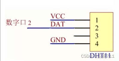
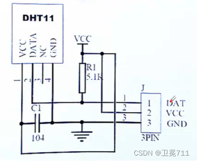
4.2 Sensor interface
- VCC — power supply pin 5V
- GND — power supply pin GND
- DAT — Digital pin 2
4.3 Arduino code display [package library]
#include "dht11.h" //封装库的头文件

dht11 DHT11; //构造函数封装实例化

#define DHT11PIN 2 //定义引脚

void setup(){


	Serial.begin(9600); //串口通信
	Serial.println("DHT11 TEST PROGRAM");
	Serial.print("LIBRARY VERSION");
	Serial.println(DHT11LIB_VERSION);
	Serial.println();
}

void loop(){


	Serial.println("\n");

	int chk = DHT11.read(DHT11PIN); //返回值为chk

	Serial.print("Read sensor: ");
	switch(chk){


		case DHTLIB_OK
			Serial.println("OK");
			break;
		case DHTLIB_ERROR_CHECKSUM
			Serial.println("Checksum error");
			break;
		case DHTBIL_ERROR_TIMEOUT
			Serial.println("Time out error");
			break;
		default:
			Serial.println("Unknown error");
			break;
	}

	Serial.print("Humidity(%): "); //打印湿度
	Serial.print((float)DHT11.humidity, 2); //显示两位小数

	Serial.print("Temperature(oC): "); //打印温度
	Serial.print((float)DHT11.temperature, 2);

	Serial.print("Temperature(oF): "); //打印温度
	Serial.print(Fahrenheit(DHT11.temperature), 2);

	Serial.print("Temperature(K): "); //打印温度
	Serial.print(Kelvin(DHT11.temperature), 2);

	Serial.print("Dew Point(oC): "); //打印
	Serial.print(dewPoint(DHT11.temperature, DHT11.humidity));

	Serial.print("Dew PointFast(oC): "); //打印
	Serial.print(dewPoint(DHT11.temperature, DHT11.humidity));

	delay(2000);


	}
}