1. Experiment name
Switch configuration and VLAN division
2. The purpose of the experiment
(1) Master the initial configuration and remote management of switches.
(2) Master the port-based VLAN division method of the switch.
(3) Grasp the role of VLAN.
Three. Four experimental topology diagrams, device names and parameter configurations
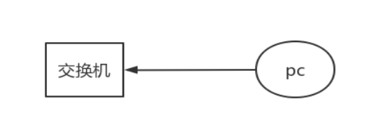
Experiment 1: Initial Switch Configuration
Figure 1. Switch initial configuration experiment
Experiment 2: Remote Management of Switches
Figure 2. Switch remote management
Experiment 3: Port-based VLAN division
Figure 3. Experiment based on port vlan division
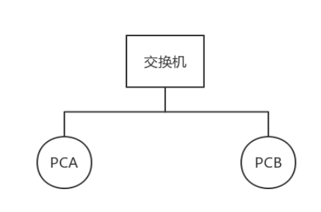
- PCA IP address information: 192.168.0.1 255.255.255.0
- PCB IP address information: 192.168.0.3 255.255.255.0
Experiment 4: VLAN communication between two switches
Figure 4 VLAN communication experiment between two switches

- PCA IP address information: 192.168.0.1 255.255.255.0
- PCB IP address information: 192.168.0.3 255.255.255.0
- PCC IP address information: 192.168.0.4 255.255.255.0
- PCD IP address information: 192.168.0.5 255.255.255.0
- Experimental equipment: four PCs, two switches, two switch configuration cables; several network cables.
4. The main steps of the experiment and the explanation of the phenomenon
Experiment 1: Initial configuration of the switch
- Connect the switch and PCA (192.168.0.1 255.255.255.0) according to the above figure, click "Start-Programs-Accessories-Communication-HyperTerminal" to start the HyperTerminal program;
- Set the parameters of the com1 port (select "restore to default value"), select "OK", and enter the user view of the switch configuration interface.
- Configure the remote login management switch
a) Configure the IP address information required for remote management of the switch
< Quidway > system view (enter the system view from the user view)
[Quidway]interface vlan-interface 1 (enter the virtual interface 1 view)
[Quidway-Vlan-interface1 ]ip address 192.168.0.2 255.255.255.0
[Quidway-Vlan-interface1]quit
b) Configure authority switch remote administrator authority, password
[Quidway]user-interface vty 0 4 (allow 0-4 five virtual user terminal interfaces)
[ Quidway-ui-vty0-4]set authentication password simple 123
[Quidway-ui-vty0-4]user privilege level 3 (four levels of authority from 0-3, set as the highest authority)
[Quidway-ui-vty4]quit
[Quidway ]quit (exit the system view and enter the user view)
c) Save the switch configuration information in the user view
< Quidway >save (save the switch system configuration parameter information)
Experimental Content 2: Remote Management of Switches
Configuration steps and commands:
- Remove the switch initial configuration cable.
- Open the switch remote management host PCA (192.168.0.1), and connect PCA to any Ethernet interface of the switch with a twisted pair.
- Click "Start-Run-cmd" to enter the DOS interface, type "telnet 192.168.0.2 (the IP address configured on the virtual interface during the initial configuration of the switch)" and enter the password "123" to enter the switch management platform. (Using the experimental content and the initial configuration results of a pair of switches to realize remote management of switches)
Experiment 3: Port-based VLAN division
Configuration steps and commands:
- [Quidway]vlan 2 (create virtual LAN 2)
- [Quidway-vlan2]port e0/9 to e0/12 (divide Ethernet 9-12 ports to vlan 2)
- [Quidway-vlan2]vlan 3 (create virtual LAN 3)
- [Quidway-vlan3]port e0/13 to e0/16 (divide Ethernet 13-16 ports to vlan 3)
- [Quidway-vlan4]quit
- Put PCA and PCB in the same virtual local area network interface, test with Ping command, and observe the experimental phenomenon.
success, 0% loss - Put PCA and PCB in different virtual local area network interfaces, test with Ping command, and observe the experimental phenomenon.
fail, 100% loss
After configuration, connect the two hosts to the same switch with twisted pair cables, the IP addresses are 10.0.0.3 and 10.0.0.4 respectively, and then put the two hosts in the same vlan, and then use the command ping, the two hosts can communicate successfully; but When the two hosts are in different vlans, use the ping command and find that the receive 0, 100% packet loss rate, indicates that the vlan division is successful.
Experiment 4: VLAN communication between two switches
Configuration steps and commands:
- The front and rear groups use twisted pairs to connect the two switches through ports that are not assigned to the new vlan (such as: e0/18)
; - Use the Ping command to test the hosts in the same vlan 2 on different switches, and observe the experimental phenomenon.
- [Quidway]interface e0/18 (enter the 18th Ethernet port configuration interface)
- [Quidway-Ethernet0/18]port link-type trunk (set the port connection type)
- [Quidway-Ethernet0/18]port trunk permit vlan 2 (allow vlan 2 to pass)
- Use the Ping command to test the hosts in the same vlan 2 on different switches, and observe the experimental phenomenon.
Success, 0% loss. - Use the Ping command to test the hosts in the same vlan 3 on different switches, and observe the experimental phenomenon.
Success, 0% loss.
Connect the two switches through an interface that is not divided into vlans. First, test the two hosts that are in the same vlan 2 but not in the same switch. It is found that the communication cannot be successful. Then configure the switch interface and set it to allow vlan 2 to communicate. Test the same vlan again. 2 But the two hosts that are not in the same switch, use the command ping test, and find that they can communicate successfully, but test the two hosts that are in vlan 3 but not in the same switch, use the command ping test, and find that the communication cannot be successful, so you want to make Two hosts in the same virtual LAN but not in the same switch communicate successfully, and need to enter the switch configuration page separately for configuration.
5. Review the information and answer the following questions:
(1) Briefly describe the commonly used network connection devices and their characteristics of different levels of extended LAN.
- Physical layer: repeaters and hubs. It is used to connect network segments with the same physical characteristics, and these network segments only have different locations. Hub The main function of the hub is to regenerate, reshape and amplify the received signal to expand the transmission distance of the network. At the same time, it concentrates all nodes on the port on the node centered on it. The hub has no physical and logical addresses.
- Logical link layer: bridge (Bridge) and switch (Switch). It is used to connect network segments with different physical layer specifications in the same logical network. The topological structure of these network segments and the format of data frames on them can be different. Ports of Bridge and Switch have physical addresses but no logical addresses.
- Network layer: router. Used to connect different logical networks. Each port of the router has a unique physical address and logical address.
- Application layer: gateway. Used for data communication between applications using different protocols on an interconnected network.
(2) Briefly describe the main internal components and working principles of the bridge.
The basic structure of a bridge generally consists of a processor, a read-only memory, a station table, and two LAN controllers. The processor and the two LAN controllers perform the control tasks of the entire bridge, including allocating buffers for the LAN controllers, determining Whether to forward the fake frames, provide network management services and station table maintenance. The station table stores the address of each station registered in the network and the address of the bridge commodity to reach these stations, and the local area controller is also used to complete Some specific LAN operations, such as media intervention and frame formatting.
working principle:
- When a bridge receives a frame, it first sends it to the data link layer for error checking
- Check the MAC address of the received frame, and determine which port the frame is forwarded to by looking up the station table. If the destination address and source address of the data packet are in the same interface segment, the packet will not be forwarded
- If there is no forwarding port information in the station table, it will be forwarded to all ports in the form of broadcast.
(3) Briefly describe the self-learning process of the internal station table of the bridge.
After the bridge is started, the switch whose initial forwarding table is empty receives a frame, first writes the source address of the frame, the associated port, the entry time, etc. This frame (in the MAC address column, the destination address cannot be found) broadcasts this frame to all other ports.
(4) Briefly describe the causes of VLAN and the advantages and disadvantages of commonly used division methods.
Causes:
Causes of VLAN: Although all ports of the switch are in different collision domains, they are still in the same broadcast domain. In order to avoid broadcast storms, enhance network security, facilitate network member management, and reduce the overhead of dealing with user site movement, virtual local area network (VLAN) technology is required to implement broadcast domain restrictions.
Advantages and disadvantages of commonly used partitioning methods:
-
Port-based VLAN;
advantage: Easy to operate, easy to implement
shortcoming: Leaving the original port and entering a new port, the VLANID needs to be redefined -
VLAN based on MAC address division;
advantage: Change the port without reconfiguration
shortcoming: All users need to be configured during initialization. When the number of hosts is large, the workload is heavy; because each port of the switch may need to save the MAC addresses of multiple hosts, which reduces the execution efficiency of the switch. -
Divide based on IP address:
consider any host belonging to the same IP broadcast group as belonging to the same VLAN.
advantage: Good flexibility and scalability, can easily expand the network through the router.
shortcoming: Not suitable for LAN, not efficient. -
Division based on network protocols:
VLANs can be divided into VLANs such as IP/IPX/DECnet/AppleTalk/Banyan based on the network layer protocols used. This method of dividing according to the network layer protocol can make the broadcast domain span multiple switches, which is very attractive to network administrators who want to organize users for applications and services.
advantage: After the physical location of the user host is changed, the VLAN network to which it belongs does not need to be reconfigured; it is suitable for scenarios where users need to be organized for different applications and services.
shortcoming: It takes processing time to check the network layer address of each data packet, and the efficiency is low. -
Policy-based division:
According to different situations, multiple technologies (mentioned above) for dividing VLANs are used comprehensively according to certain security policies.
advantage: This method has the ability of automatic configuration and high degree of automation; it can expand the network scale very conveniently.
shortcoming: Higher requirements on equipment.