This chapter builds an experimental test platform to test the hardware functions and system task communication functions of the multi-axis motion control platform.
carry out testing. Through the test results, verify the correctness of the platform hardware design and real-time processing and synchronization control of the system
functional and performance verification.
5.1
Test platform construction
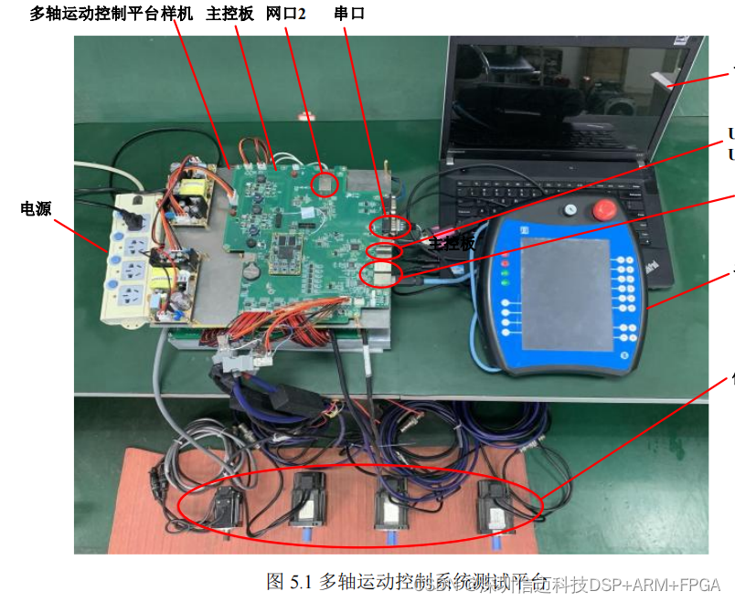
The test platform of the multi-axis motion control system is shown in Figure
5.1
. The test platform consists of a safe power supply, multi-axis
The moving platform prototype (including the main control board
MC
), the upper computer
PC
, the handheld box and four
80ST-M0 1330LMB
Hua
Large AC servo motor (built-in
17
-bit absolute encoder). Prototype through motor power interface and encoder
The interface is connected with four servo motors.
The hardware test of the motion control platform mainly includes
UART
serial port,
USB 2.0
and Ethernet interface function test
try. The task communication test of the platform system includes two parts: function realization and performance. Among them, functional testing checks
Whether the periodic task communication and non-periodic task communication between dual cores are normally implemented; performance test checks the motion control system
real-time and synchronous control functions. Finally, run the robot control software on the platform and connect the hand-held box to test
The running effect of the whole machine.
5.2
Motion control platform hardware function test
5.2.1 UART
interface test
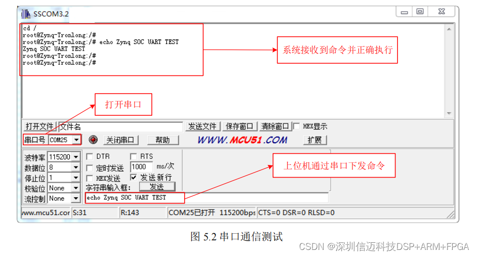
Connect the control platform to the Windows host through the
UART interface, and use
SSCOM3.2 software to
Run the serial port test. As shown in Figure
5.2
, the platform
UART
interface
is correctly recognized as COM25 in
Windows
.
Open the serial port in the
SSCOM software and send commands to
the Linux
system. Observe through the message window,
the Linux
system
The system correctly receives the command and executes it.
The test results show that the UART interface
of the system
is functioning normally.
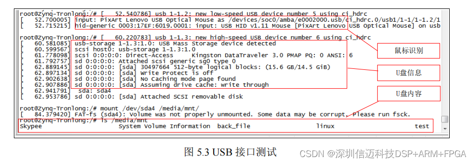
5.2.2 USB
interface test
The platform has two
USB 2.0
interfaces, and functional tests are carried out on them respectively. The system connects the interface
USB0
with the mouse
Connect the interface
USB1
to
the U
disk. The test results are shown in Figure
5.3
,
the Linux
system correctly identified
Mouse and
U
disk device.
Mount the U disk through the
mount command
, and you can view the files in the U disk. The test results show that the USB interface of the system is functioning normally.
After the robot control software runs, the motion control platform communicates with the hand-held box through the Gigabit Ethernet interface.
letter.
First set the IP address
of the handheld box
to
192.168.1.114
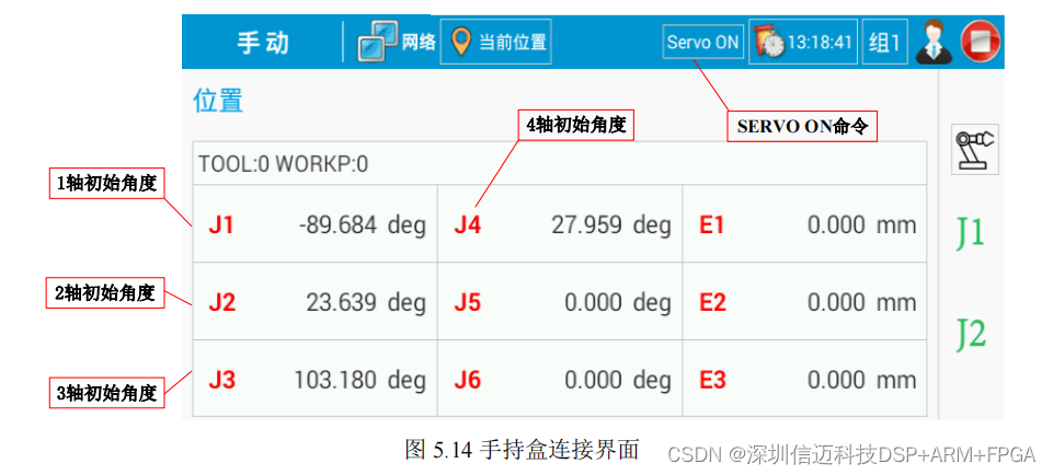
to complete the network connection with the control platform. handheld
After the box is normally connected to the motion control platform,
enable the servo system through the
SERVO ON command, and read the motion
The initial position of the four axes of the moving platform. As shown in Figure
5.14
, the handheld box software reads the initial angle of the four axes, and the
The data of the robot controller software is consistent. The test results show that the robot control software runs normally on the platform,
The platform realizes the connection and communication with the hand-held box.