<Linux development> System porting-of-the detailed record of the Linux kernel porting process (end of the second part)
Earlier, the first part explained the operation process of compiling and downloading NXP's official original Linux directly to the development board, and the test effect. And some auxiliary tools designed and used in the process. From the first part, you can be familiar with the whole process of Linux compilation to downloading and running, which is convenient for the next porting operation.
For uboot porting, please refer to:
<Linux development> -The detailed record of the uboot transplantation process of system transplantation (Part 1)
<Linux development> -The detailed record of the uboot transplantation process of system transplantation (Part 2) <Linux development> -The detailed record of
the uboot transplantation process of system transplantation Records (Part 3) (Completed uboot porting)
For Linux kernel and device tree transplantation, please refer to:
<Linux Development> System Migration - of - Linux Kernel Migration Process Detailed Record (Part 1)
This is the second part of Linux porting in Linux system porting. It mainly explains and records the process of porting NXP original Linux to Punctual Atomic Linux development board. The operation process refers to the official Linux development manual of Punctual Atom. If the explanation is not detailed, wrong or omitted, you can contact the author to modify and supplement, or refer to the official information of Punctual Atom.
Contact QQ: 759521350
Note: The author uses the Linux development board of the IMX6ULL-EMMC version of Punctual Atom.
Next, the main process records are explained.
1. Add the model of the development board used in the Linux source code 1. Add the
default configuration file of the development board
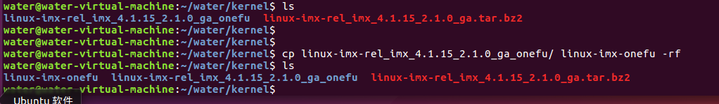
(1) Copy the unzipped folder from the first part, and rename it to "linux-imx-onefu"
command:
cp linux-imx-rel_imx_4.1.15_2.1.0_ga_onefu/ linux-imx-onefu -rf
(2) Add the default configuration file of the development board used.
Copy the imx_v7_mfg_defconfig in the arch/arm/configs directory and name it imx_onefu_emmc_defconfig. The command is as follows:
cd arch/arm/configs/
cp imx_v7_mfg_defconfig  imx_onefu_emmc_defconfig
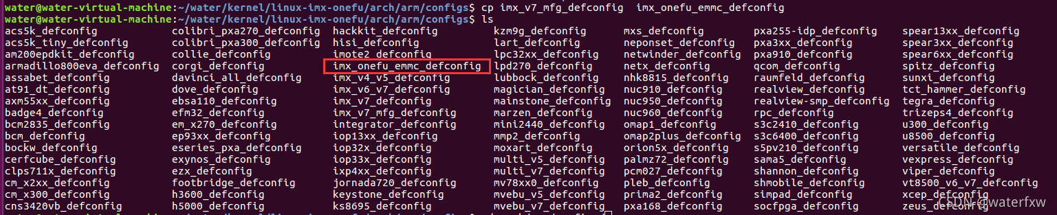
In the follow-up development, imx_onefu_emmc_defconfig will be used as the configuration file of Punctuality Atomic Linux-emmc development board.
(3) Add the device tree file of the
development board used Add the device tree file of the development board, enter the directory arch/arm/boot/dts, copy a copy of imx6ull-14x14-evk.dts, and then rename it to imx6ull-onefu -emmc.dts, the command is as follows:
cd arch/arm/boot/dts/
cp imx6ull-14x14-evk.dts imx6ull-onefu-emmc.dts

.dts is the source file of the device tree, which is compiled into a .dtb file when compiling Linux.
2. Modify the transplant file
1. Modify the device tree file
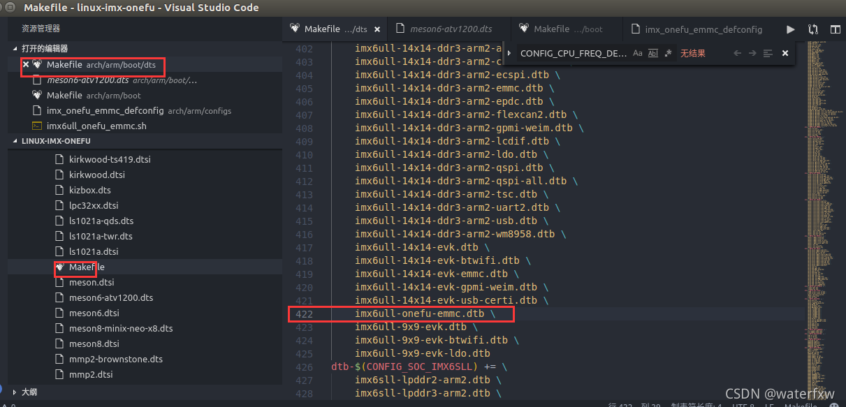
Open it with VScode, find the "arch/arm/boot/dts/Makefile" in the path, and find the "dtb-$(CONFIG_SOC_IMX6ULL)" configuration item in this file. Add the following:
imx6ull-onefu-emmc.dtb \
As shown in the figure below, this sentence is the "imx6ull-onefu-emmc.dts" device tree file added earlier. After compilation, a .dtb device tree file is generated, and the .dtb device tree file is downloaded to the Linux development board for use.
Note: to have slashes...
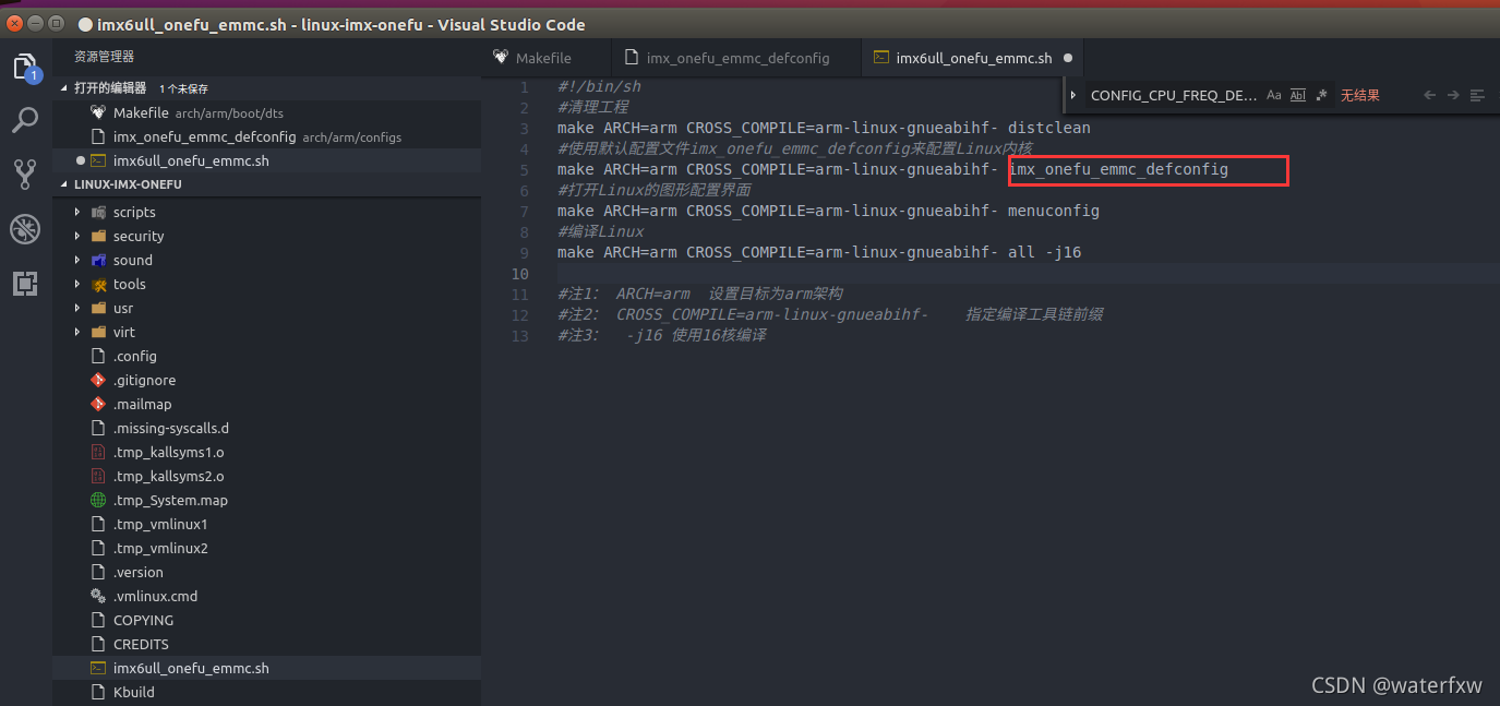
2. Modify the script file
The script "imx6ull_onefu_emmc.sh" written when testing NXP original Linux is as follows:
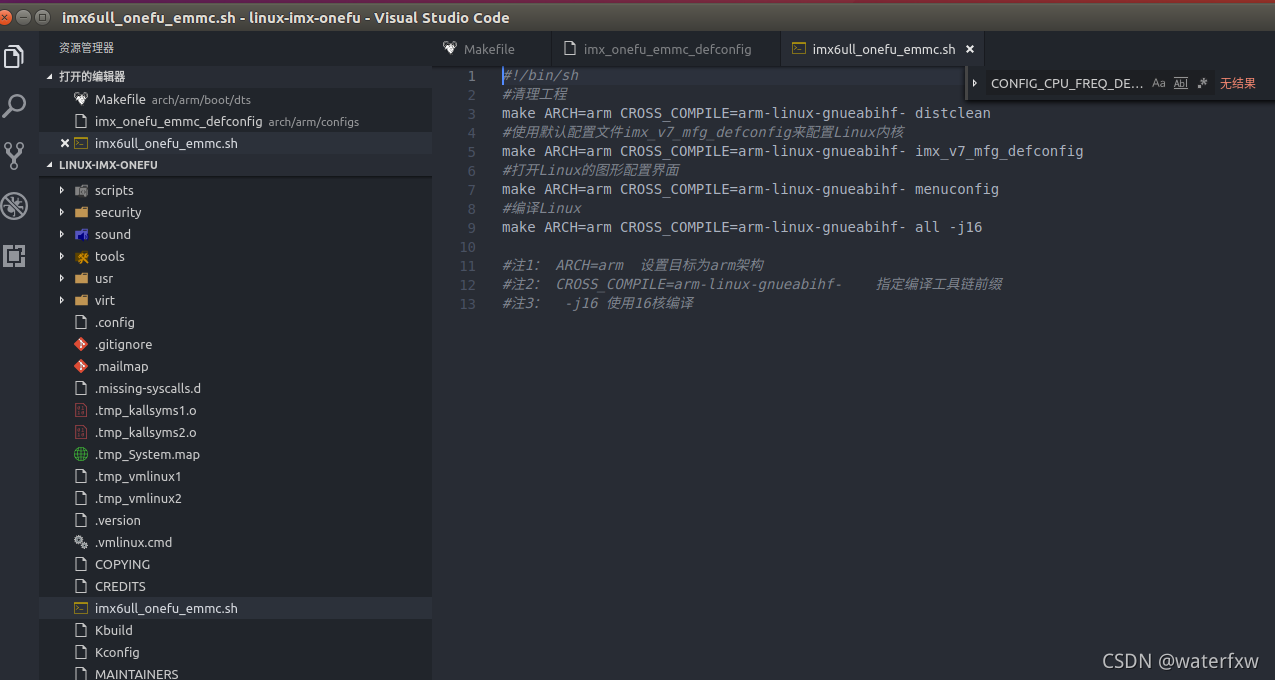
After transplanting to the development board, the modification is as follows:
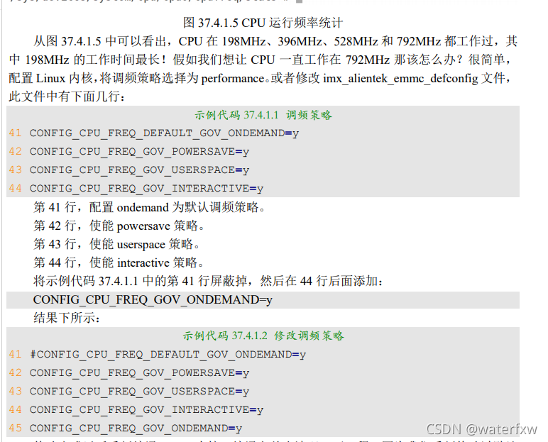
3. Modification of the main frequency
According to the official documentation of Atomic, the main frequency of the I.MX6ULL chip used in the I.MX6U-ALPHA development board of Atomic is 792MHz, which is the 800MHz version officially promoted by NXP.
Next, modify the operating frequency of the CPU.
Open "arch/arm/configs/imx_onefu_emmc_defconfig" and find the following sentences:
CONFIG_CPU_FREQ_GOV_POWERSAVE=y //使能powersave策略
CONFIG_CPU_FREQ_GOV_USERSPACE=y //使能userspace策略
CONFIG_CPU_FREQ_GOV_ONDEMAND=y  //配置ondemand为默认调频策略。
CONFIG_CPU_FREQ_GOV_CONSERVATIVE=y//直接上最高频率,然后看CPU负荷慢慢降低
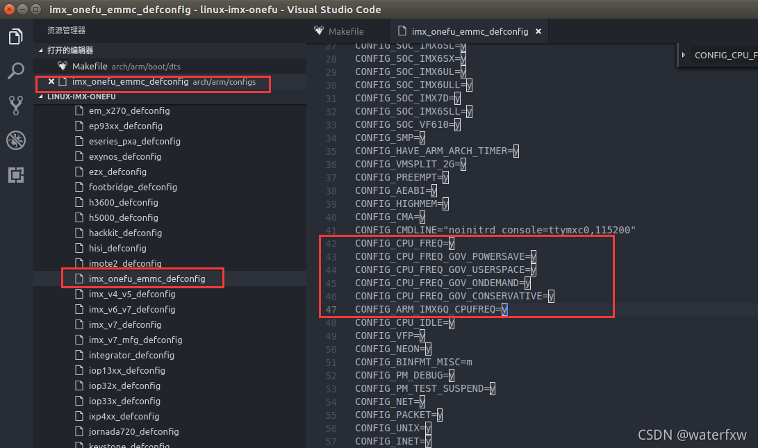
Check if there is "CONFIG_CPU_FREQ_GOV_ONDEMAND=y", if not, add it, otherwise do not modify it.
View the configuration according to the specific opened file. **The official instruction manual of the punctual atom is different from the above picture,** so you need to add the corresponding statement as above. However, in this operation, the configuration already exists "CONFIG_CPU_FREQ_GOV_ONDEMAND=y", so there is no need to change it.
The screenshot of the Punctuality Atomic Manual is as follows:
4. Enable 8-wire EMMC driver
The Linux kernel driver uses EMMC in 4-wire mode by default, and 4-wire mode is definitely not as fast as 8-wire mode. The driver of the EMMC needs to be modified to 8-wire mode. The modification method is very simple, just modify the device tree directly, open the file imx6ull-onefu-emmc.dts, and find the following content:
&usdhc2 {


	pinctrl-names = "default";
	pinctrl-0 = <&pinctrl_usdhc2>;
	non-removable;
	status = "okay";
};

Modified as follows:
&usdhc2 {


	pinctrl-names = "default", "state_100mhz", "state_200mhz";
	pinctrl-0 = <&pinctrl_usdhc2_8bit>;
	pinctrl-1 = <&pinctrl_usdhc2_8bit_100mhz>;
	pinctrl-2 = <&pinctrl_usdhc2_8bit_200mhz>;
	bus-width = <8>;
	non-removable;
	status = "okay";
};

5. Modify the network driver
The network debugging driver is used when the Linux driver is developed, so the network driver must be debugged well. When explaining the uboot porting, I already said that the network of the punctual atomic development board is different from the official network hardware of NXP. The network PHY chip is changed from KSZ8081 to LAN8720A, and the reset IO of the two network PHY chips is also different. Therefore, the network driver that comes with the Linux kernel cannot drive the network on the I.MX6U-ALPHA development board, and needs to be modified.
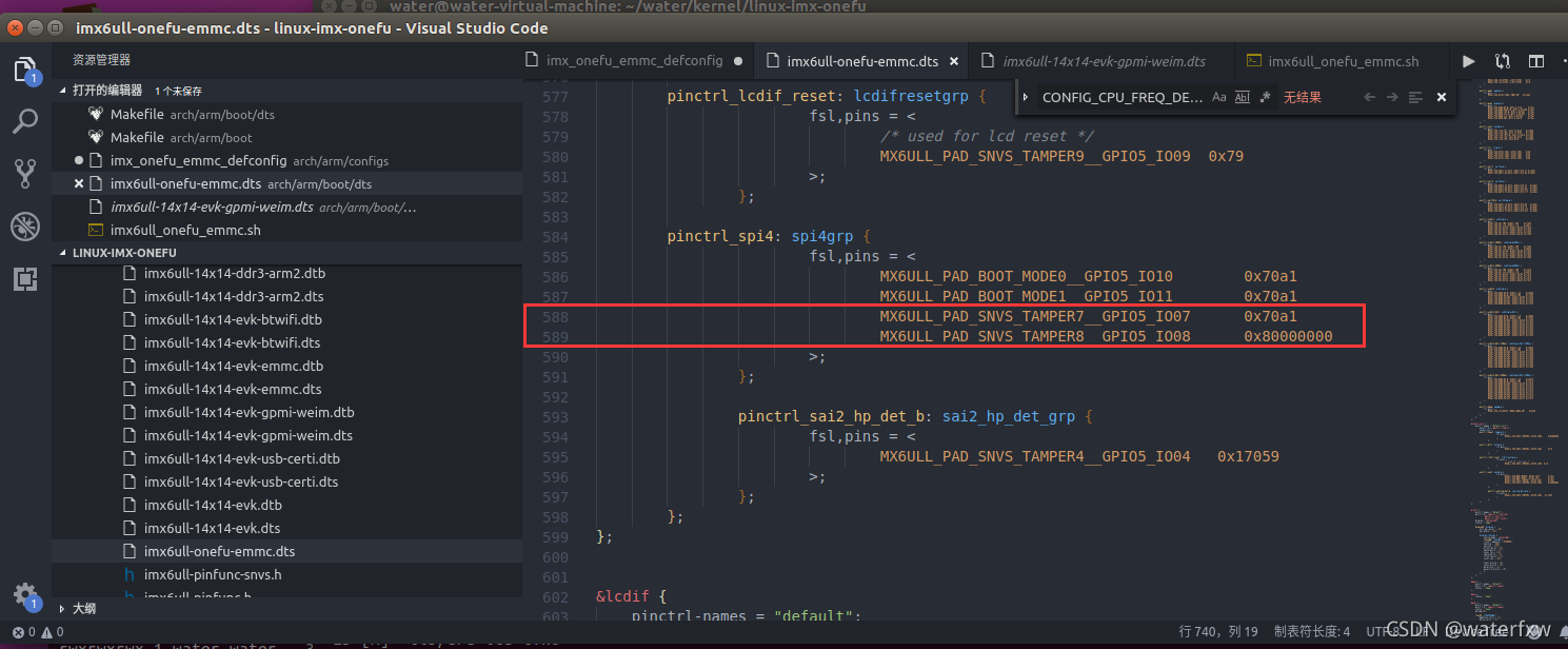
(1) Modify the reset of the LAN8720 and the network clock pin driver
Open "arch/arm/boot/dts/imx6ull-onefu-emmc.dts"
a. Delete the old network pin configuration of the NXP original factory. Delete the
red boxed part of the screenshot below:
b. Add the network pin of the punctual atom Linux development board
. Find the node named "iomuxc_snvs" in imx6ull-onefu-emmc.dts (that is, Search directly), and then add the network reset pin information under this node. After the addition is complete, the node content of "iomuxc_snvs" is as follows:
&iomuxc_snvs {


	pinctrl-names = "default_snvs";
        pinctrl-0 = <&pinctrl_hog_2>;
        imx6ul-evk {


		省略..........................
		/*enet1 reset water*/
		pinctrl_enet1_reset: enet1resetgrp {


				fsl,pins = <
				/* used for enet1 reset */
				MX6ULL_PAD_SNVS_TAMPER7__GPIO5_IO07 0x10B0
				>;
		};
		/*enet2 reset water*/
		pinctrl_enet2_reset: enet2resetgrp {


				fsl,pins = <
				/* used for enet12 reset */
				MX6ULL_PAD_SNVS_TAMPER8__GPIO5_IO08 0x10B0
				>;
		};
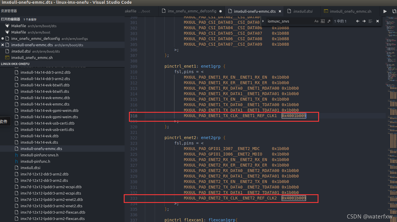
Modify the network clock pin configuration of ENET1 and ENET2, and continue to find it in imx6ull-onefu-emmc.dts. After modification, the code is as follows:
(2) Modify the pinctrl-0 attribute of fec1 and fec2 nodes
in imx6ull-alientek-emmc Find the two nodes named "fec1" and "fec2" in the
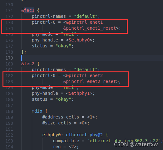
.dts file, and modify the "pinctrl-0" attribute value
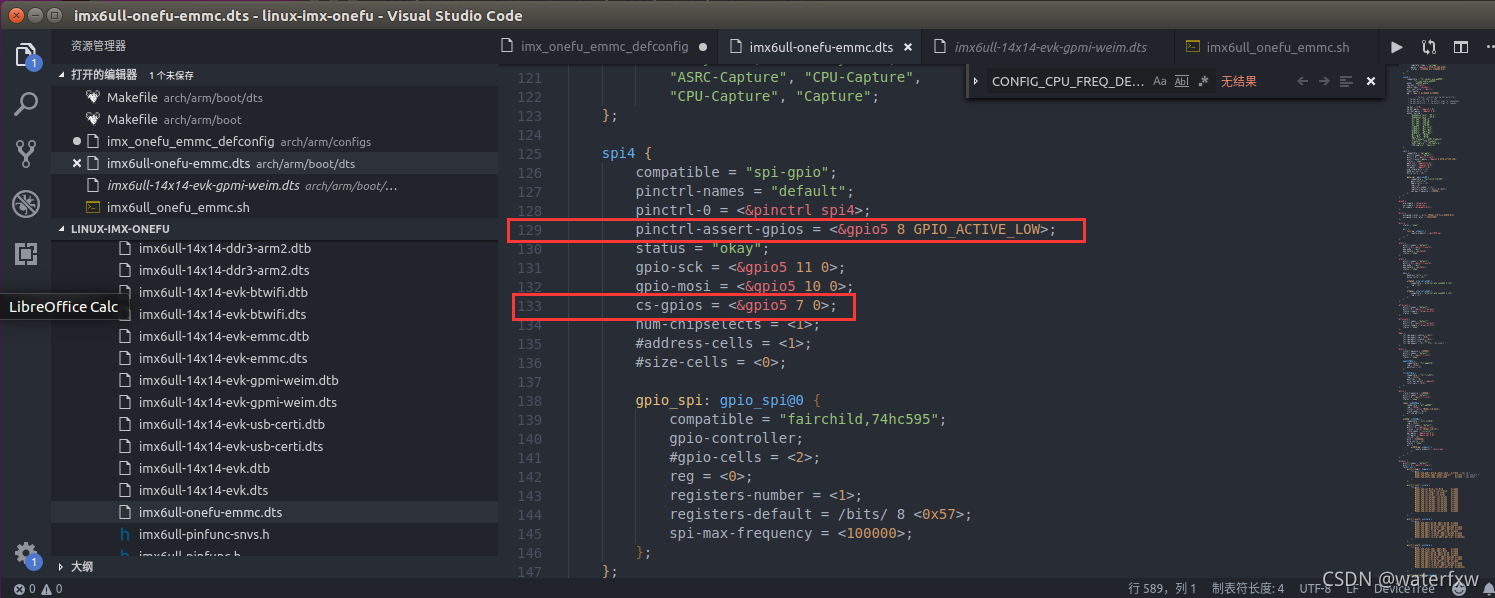
. The LAN8720A address of ENET2 is 0x1; find the nodes fec1 and fec2 in imx6ull-alientek-emmc.dts, which are modified as follows:
&fec1 {
pinctrl-names = "default";
pinctrl-0 = <&pinctrl_enet1
&pinctrl_enet1_reset>;
phy-mode = "rmii";
phy-handle = <ðphy0>;
phy-reset-gpios = <&gpio5 7 GPIO_ACTIVE_LOW>;
phy-reset-duration = <200>;
status = "okay";
};
&fec2 {
pinctrl-names = "default";
pinctrl-0 = <&pinctrl_enet2
&pinctrl_enet2_reset>;
phy-mode = "rmii";
phy-handle = <ðphy1>;
phy-reset-gpios = <&gpio5 8 GPIO_ACTIVE_LOW>;
phy-reset-duration = <200>;
status = "okay";
mdio {
#address-cells = <1>;
#size-cells = <0>;
ethphy0: ethernet-phy@0 {
compatible = "ethernet-phy-ieee802.3-c22";
smsc,disable-energy-detect;
reg = <0>;
};
ethphy1: ethernet-phy@1 {
compatible = "ethernet-phy-ieee802.3-c22";
smsc,disable-energy-detect;
reg = <1>;
};
};
};
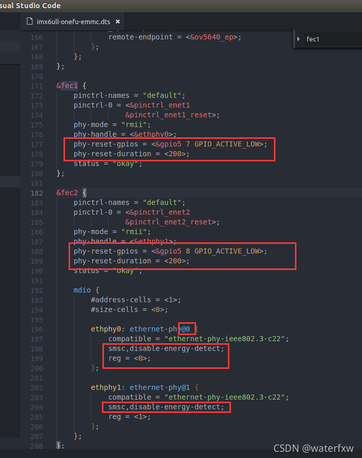
Lines 177 and 178, add that the IO used by the ENET1 network reset pin is GPIO5_IO07, which is active low. The duration of the reset low level signal is 200ms.
Lines 188 and 189, the IO used by the ENET2 network reset pin is GPIO5_IO08, which is also active low and the duration is also 200ms.
Lines 198 and 204, "smsc, disable-energy-detect" indicates that the PHY chip is from SMSC, so the Linux kernel will find the PHY chip driver from SMSC to drive the LAN8720A.
Line 196, note that the number after "ethernet-phy@" is the address of the PHY, the PHY address of ENET1 is 0, so the "@" is followed by 0 (default is 2).
Line 199, the value of reg also represents the PHY address, the PHY address of ENET1 is 0, so reg=0.
Line 202, the PHY address of ENET2 is 1, so the "@" is followed by 1.
Line 205, because the PHY address of ENET2 is 1, so reg=1.
At this point, the PHY address of LAN8720A has been changed, save the imx6ull-alientek-emmc.dts file. Then use the "make dtbs" command to recompile the device tree.
(4) Modify the fec_main.c file
To use the LAN8720A on the I.MX6ULL, you need to modify the Linux kernel source code, open drivers/net/ethernet/freescale/fec_main.c, find the function fec_probe, and add the following code to fec_probe:
/* 设置MX6UL_PAD_ENET1_TX_CLK和MX6UL_PAD_ENET2_TX_CLK
 * 这两个IO的复用寄存器的SION位为1。
 */
	void __iomem *IMX6U_ENET1_TX_CLK;	//定义映射后的地址指针
	void __iomem *IMX6U_ENET2_TX_CLK;	//定义映射后的地址指针

	IMX6U_ENET1_TX_CLK = ioremap(0X020E00DC, 4);	//映射地址
	writel(0X14, IMX6U_ENET1_TX_CLK);				//写寄存器数据

	IMX6U_ENET2_TX_CLK = ioremap(0X020E00FC, 4);	//映射地址
	writel(0X14, IMX6U_ENET2_TX_CLK);				//写寄存器数据
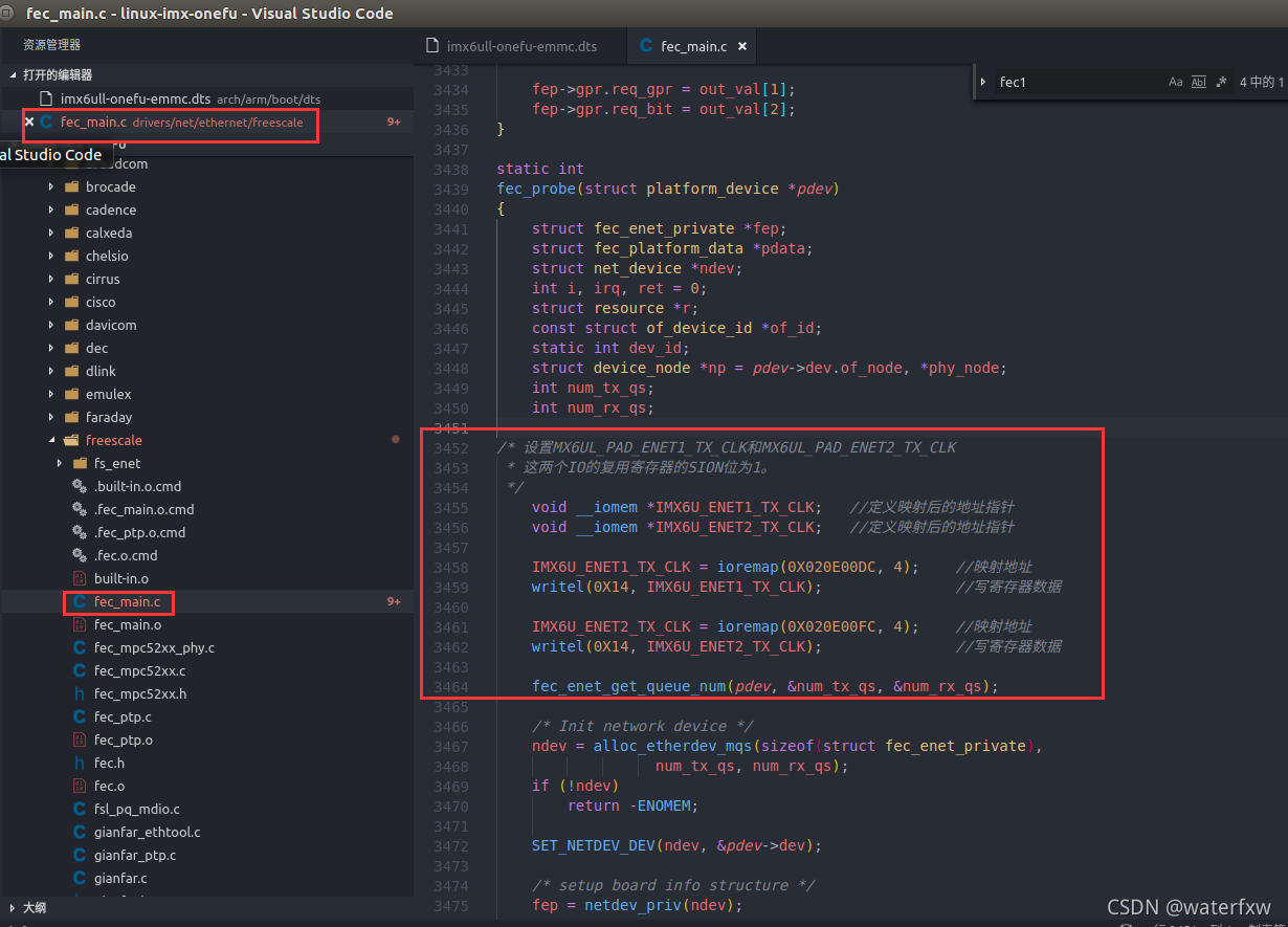
3455~3462 are the newly added codes. If you want to use the LAN8720A on the i.MX6ULL, you need to set the SION bit of the TX_CLK pin reset register of ENET1 and ENET2 to 1.
6. Configure the Linux kernel and enable the LAN8720 driver.
Enter the command "make menuconfig" to open the graphical configuration interface and select the driver that enables the LAN8720A. The path is as follows:
-> Device Drivers
-> Network device support
-> PHY Device support and infrastructure
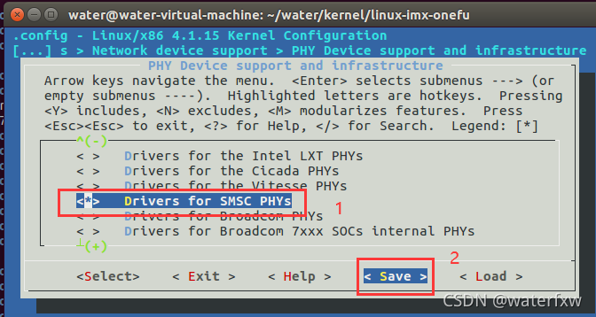
-> Drivers for SMSC PHYs
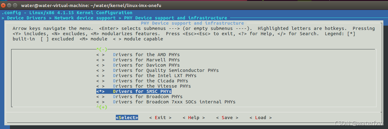
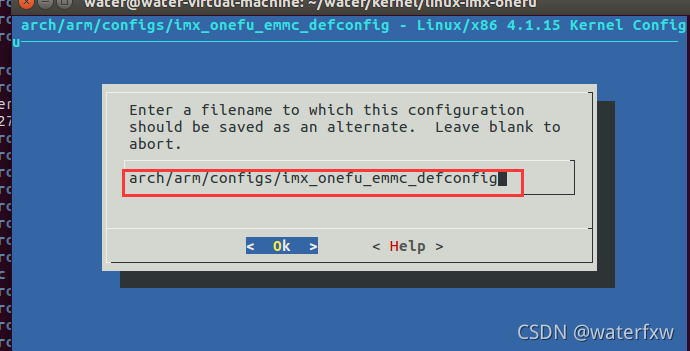
After selecting "Drivers for SMSC PHYs", press "y", after pressing, * will appear in the square brackets in front of the option, LAN8720A is produced by SMSC, so after checking this, the LAN8720 driver will be compiled, after configuration, Press "→" on the keyboard, move to "Save", then press the Enter key, enter "arch/arm/configs/imx_onefu_emmc_defconfig" in the pop-up dialog box, and then select "OK". Exit the configuration interface, and then recompile the Linux kernel.

7. To modify the smsc.c file,
you need to find the driver file of the LAN8720A. The driver file of the LAN8720A is drivers/net/phy/smsc.c. In this file, there is a function called smsc_phy_reset. You can see by the name that this is the reset of the SMSC PHY. Therefore, LAN8720A will definitely use this reset function, modify the content of this function, and the content of the smsc_phy_reset function after modification is as follows:
static int smsc_phy_reset(struct phy_device *phydev)
{


	int err, phy_reset;
	int msec = 1;
	struct device_node *np;
	int timeout = 50000;
	if(phydev->addr == 0) /* FEC1 */ {


		np = of_find_node_by_path("/soc/aips-bus@02100000/ethernet@ 02188000");	/*查找设备节点*/
		if(np == NULL) {


			return -EINVAL;
		}
	}

	if(phydev->addr == 1) /* FEC2 */ {


		np = of_find_node_by_path("/soc/aips-bus@02000000/ethernet@ 020b4000"); /*查找设备节点*/
		if(np == NULL) {


			return -EINVAL;
		}
	}

	err = of_property_read_u32(np, "phy-reset-duration", &msec);		/*读取只有一个整形值的属性*/
	/* A sane reset duration should not be longer than 1s */
	if (!err && msec > 1000)
		msec = 1;
	phy_reset = of_get_named_gpio(np, "phy-reset-gpios", 0);
	if (!gpio_is_valid(phy_reset))
		return;
	gpio_direction_output(phy_reset, 0);		/*设置GPIO的输出方向-0:输出*/
	gpio_set_value(phy_reset, 0);				/*设置GPIO的为0*/
	msleep(msec); 								/*延时1ms*/
	gpio_set_value(phy_reset, 1);				/*设置GPIO的为1*/

	int rc = phy_read(phydev, MII_LAN83C185_SPECIAL_MODES);
	if (rc < 0)
		return rc;

	/* If the SMSC PHY is in power down mode, then set it
	 * in all capable mode before using it.
	 */
	if ((rc & MII_LAN83C185_MODE_MASK) == MII_LAN83C185_MODE_POWERDOWN) {


		int timeout = 50000;

		/* set "all capable" mode and reset the phy */
		rc |= MII_LAN83C185_MODE_ALL;
		phy_write(phydev, MII_LAN83C185_SPECIAL_MODES, rc);
		phy_write(phydev, MII_BMCR, BMCR_RESET);

		/* wait end of reset (max 500 ms) */
		do {


			udelay(10);
			if (timeout-- == 0)
				return -1;
			rc = phy_read(phydev, MII_BMCR);
		} while (rc & BMCR_RESET);
	}
	return 0;
}
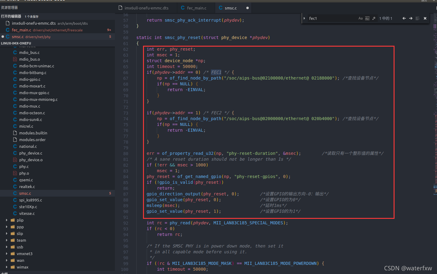
Lines 7 to 12, obtain the device node corresponding to the FEC1 network card.
Lines 14 to 19, obtain the device node corresponding to the FEC2 network card.
Line 21 obtains the "phy-reset-duration" attribute information from the device tree, that is, the reset time.
Line 25, get the "phy-reset-gpios" attribute information from the device tree, that is, reset IO.
Lines 29 to 32, set the reset IO of the PHY and reset the LAN8720A.
Lines 41 to 48, the previous smsc_phy_reset function will judge whether the LAN8720 is in Powerdown mode, and the LAN8720 will be soft reset only when it is in Powerdown mode. Here we move out the soft reset code so that the LAN8720A will be soft reset every time the smsc_phy_reset function is called.
Finally, we also need to add two header files to the drivers/net/phy/smsc.c file, because the modified smsc_phy_reset function uses the two functions gpio_direction_output and gpio_set_value. The header files that need to be added are as follows:
#include <linux/of_gpio.h>
#include <linux/io.h>
The above is the transplantation and modification on the basis of the Linux officially provided by NXP, and the transplantation is used on the Linux development board that conforms to the punctual atom. After the transplantation and modification, the next step is to compile and test.
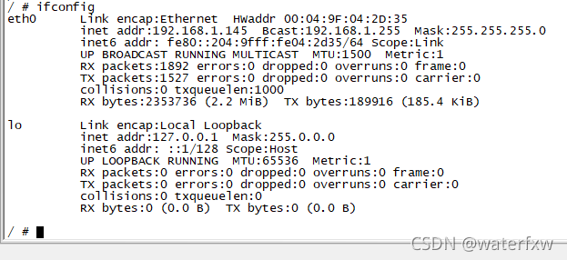
3. Network driver test
After modifying the device tree and the Linux kernel, recompile it to get a new zImage image file and imx6ull-onefu-emmc.dtb device tree file. Use a network cable to connect the two network ports of the I.MX6U-ALPHA development board Connect it with your router or computer, and finally boot the Linux kernel with the new file. After startup, use the "ifconfig" command to check which network cards are currently active. The result is shown in the following figure:
Put the newly obtained zImage and imx6ull-onefu-emmc.dtb device tree files in the folder set by the tftp server, command:
cd /home/water/linux/tftpboot    				//进入到tftp文件夹
cp /home/water/water/kernel/linux-imx-onefu/arch/arm/boot/zImage .  //复制镜像
cp /home/water/water/kernel/linux-imx-onefu/arch/arm/boot/dts/imx6ull-onefu-emmc.dtb  .   //复制设备树

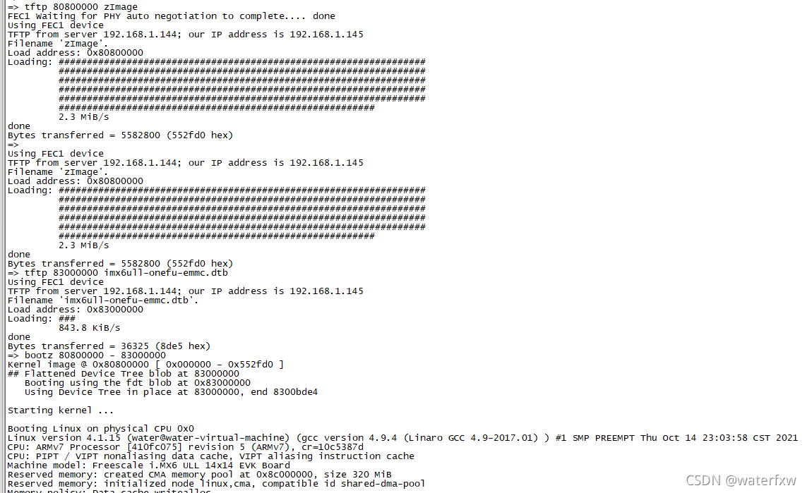
Start the development board and enter boot, and download the zImage and imx6ull-onefu-emmc.dtb device tree files.
Enter the command:
tftp 80800000 zImage
tftp 83000000 imx6ull-onefu-emmc.dtb
bootz 80800000 - 83000000
First make sure the root filesystem already exists. . . .
Use the "ifconfig" command to view the network card.
If there is no active network card, you can use the following command to check the existing network card:
ifconfig -a
Then use the following command to start the network card:
ifconfig eth0 up    //eth0表示启动的网卡名称
ifconfig eth1 up
Use the following command to set the IP address of the network card:
ifconfig eth0 192.168.1.145
ifconfig eth1 192.168.1.146
Use the "ping" command to ping the ubuntu host, the command is as follows:
ping 192.168.144
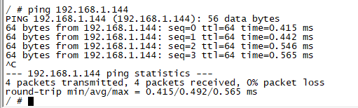
It can be seen that the ping is successful, indicating that the network driver has been modified successfully! We can use the network to debug the code in the later build root file system and Linux driver development.
The migration of the Linux kernel is explained here, and the migration steps are briefly summarized:
1. Find the reference boards in the Linux kernel, which are generally development boards made by semiconductor manufacturers themselves.
②. Compile the zImage and .dtb files corresponding to the reference board.
③. Use the zImage file and .dtb file of the reference board to start the Linux kernel on the board we are using to see if it can be started.
④. If it can be started, everything will be fine. If it cannot be started, it will be a tragedy, and the Linux kernel needs to be debugged. However, it generally refers to the official development board of the semiconductor to design its own hardware, so it will start up in most cases. There are not many peripherals used to start the Linux kernel, generally DRAM (Uboot is initialized) and serial ports. The serial port used as a terminal generally refers to the demo board of the semiconductor manufacturer.
⑤. Modify the corresponding drivers, such as NAND Flash, EMMC, SD card and other drivers. The official Linux kernel has been provided, and there will be basically no problems. The focus is on network drivers, because Linux driver development generally requires debugging code through the network, so be sure to make sure that network drivers work properly. If it is a network solution such as the internal MAC + external PHY of the processor, the general network driver is easy to handle, because there is a general driver for external PHY in the Linux kernel. As long as the reset pin is set, the PHY address information can basically be driven.
⑥. The root file system is required after the Linux kernel is started. If there is no root file system, it will definitely crash. Therefore, after the Linux kernel is successfully transplanted, the construction of the root file system must be started.
The above contents refer to the supporting materials of the punctual atomic linux development board. If there are any deficiencies, omissions or mistakes, you can contact the author for further improvement.
If you want to get more detailed information, you can download it from the official website of Punctual Atom.