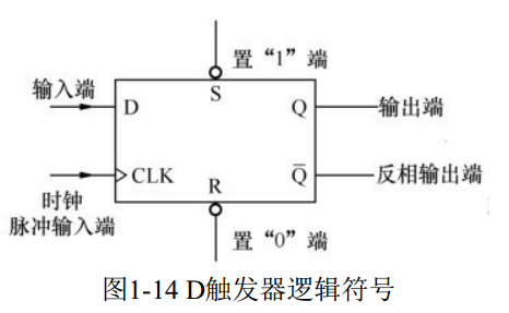
There are a large number of registers inside the single-chip microcomputer. A register is a circuit that can store data and is composed of flip-flops. 1. Trigger Trigger is a circuit with memory storage function, composed of gate circuits. Common flip-flops include: RS flip-flops, D flip-flops and JK flip-flops, among which D flip-flops are the most commonly used. The logic symbol of D flip-flop is shown in Figure 1-14
It can be seen from Figure 1-14 that the terminals of the D flip-flop include: input terminal D, output terminal Q, inverted output terminal, clock pulse input terminal CLK, terminal R set to "0" and terminal S set to "1". Data storage process: When the D terminal of the D flip-flop inputs data "1", the data cannot be stored in the flip-flop immediately, only when the rising edge of the clock pulse signal at the CLK terminal (that is, when the low level turns to the high level) arrives, "1" can be stored in the flip-flop, after being stored, the Q terminal outputs "1" and the terminal outputs "0". In other words, only when the rising edge of the clock pulse arrives, the D flip-flop can store the data at the input terminal and output it from the Q terminal. Set “0” and “1” of D flip-flop: When the “0” terminal R is low, the flip-flop is set to “0”, that is, the Q terminal is “0”; when the “1” terminal S is At low level, the flip-flop is set to "1", that is, the Q terminal is "1".
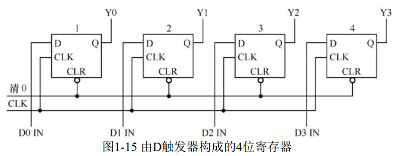
2. Register Register is the basic storage unit inside the single chip microcomputer. It is composed of flip-flops. A flip-flop is a 1-bit register. Figure 1-15 shows a 4-bit register composed of D flip-flops.
When working, the register first makes the clear line low, and sends the low level to the CLR terminal of each flip-flop (actually the R terminal of the D flip-flop), clears each flip-flop to 0, Y3Y2Y1Y0=0000; Send data to each flip-flop input terminal. When the rising edge of the clock pulse at the CLK terminal arrives, the data at the input terminal is stored in each flip-flop and output from the output terminal.
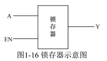
3. Latches Latches are also a circuit that can store data. Its characteristic is that when the latch signal does not come, the state of the output terminal changes with the state of the input terminal; when the latch signal comes, the data at the input terminal is latched to the output terminal, that is, the output is output when the signal at the input terminal changes again. The end will not change. Take Figure 1-16 as an example to illustrate the working principle of the latch.
When the control terminal EN of the latch is 1, the state of the output terminal Y of the latch is consistent with the state of the input terminal A, that is, when the data of the A terminal changes, the data of the Y terminal also changes; when the control terminal EN of the latch changes from " When "1" becomes "0", the data at the input terminal is immediately latched to the output terminal. During EN=0, the data at the output terminal will always remain unchanged and will not change with the input terminal; when EN becomes " 1", that is, the latch is canceled, and the output terminal will change with the change of the input terminal.