[CC2530 Introduction Tutorial-06] CC2530's ADC working principle and application
[CC2530 Introduction Tutorial-05] The principle and application of the serial interface of CC2530
[CC2530 Introduction Course-04] The principle and application of CC2530 timer/counter
[CC2530 Introduction Course-03] CC2530 Interrupt System and External Interrupt Application
[CC2530 Introduction Tutorial-02] CC2530's general I/O port input and output control
[CC2530 Getting Started Tutorial-01] CC2530 Microcontroller Development Getting Started Basics
1. What is a single chip microcomputer? https://www.cnblogs.com/ALittleBee/p/7056525.html
Single chip microcomputer: Micro controller, MCU, microcontroller, is a kind of integrated circuit chip, which has data processing capabilities of central processing unit CPU, random access memory RAM, read-only memory ROM, input and output I/O through VLSI technology. Port, interrupt control system, timer/counter and communication interface and other functional components are integrated on a silicon chip to form a small but fully functional microcomputer system. Simply put, a single chip microcomputer is a microcomputer The integrated circuit chip inside .
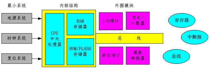
No matter complex or simple, the basic structure of the microcontroller : core + peripherals . The kernel controls the peripherals through the registers ; the peripherals notify the kernel through the interrupt system ; the kernel and the peripherals transmit data, addresses and control information through the bus . Therefore, the basic routines for embedded programmers to deal with the underlying hardware are: reading and writing registers , processing interrupt sources , and accessing internal buses .
The program development and program operation of the single-chip microcomputer are run in two systems respectively: the program is developed in the integrated development environment of the desktop computer ; the program is run in the embedded microprocessor system .

Two, CC2530 microcontroller and IAR development environment
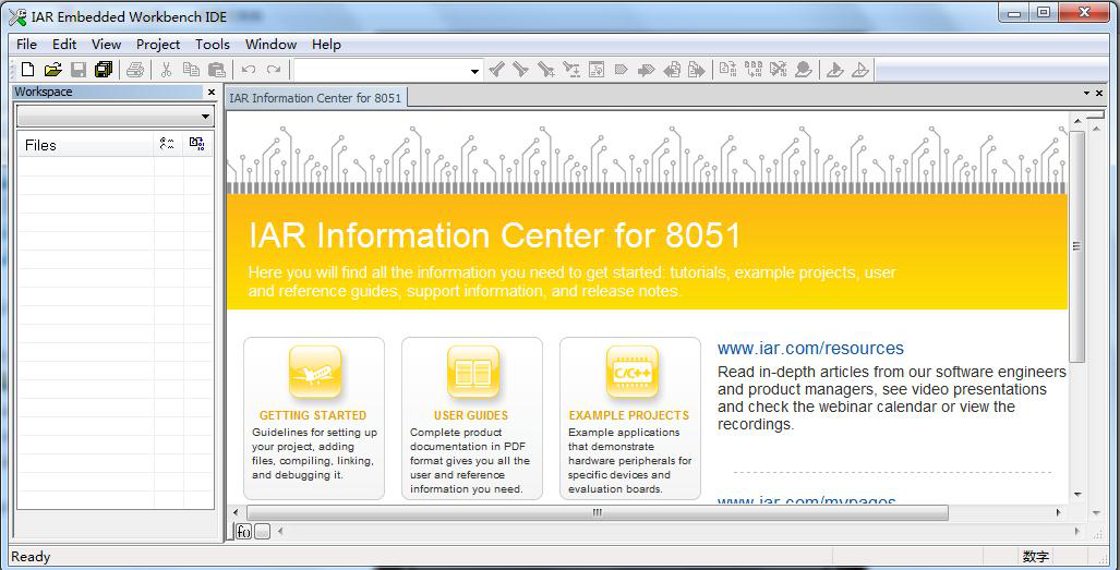
The CC2530 microcontroller uses the industry-standard enhanced 8051 core internally , combined with a leading RF transceiver, and is a system-on-chip (SOC) solution for 2.4GHz IEEE802.15.4 Zigbee applications . To carry out the application development of CC2530, you must first install the IAR-related development environment. IAR is divided into many different versions according to the types of microprocessors supported. Since CC2530 uses an enhanced 8051 core, the version that should be selected here is IAR Embedded Workbench for 8051 .
The entire CC2530 development-related environment includes:
1. Install the integrated development environment: IAR-EW8051-8101.
2. Install the driver of the emulator "SmartRF4EB".
3. Install the code burning tool: Setup_SmartRF_Programmer_1.10.2.
4. Install TI's Zigbee protocol stack: ZStack-CC2530-2.5.1a.
3. Getting started with CC2530 project development process
[1] Create a workspace
in the menu bar, File -> New -> Workspace .
[2] Create a new IAR project
in the menu bar, Project -> Create New Project...
<1> Here you can only create a new 8051 kernel project.
<2> Create a new blank project through " Empty project ".
<3>Name the new project and specify the storage path.
<4> After the creation is completed, the project will appear in the working area on the left.
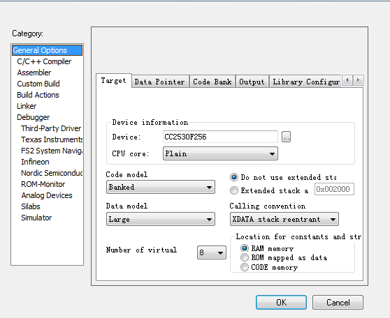
[3] Configure project options.
If you only do online simulation debugging, you only need to configure two places .
<1>Configure chip information : General Options -> Target -> Device information
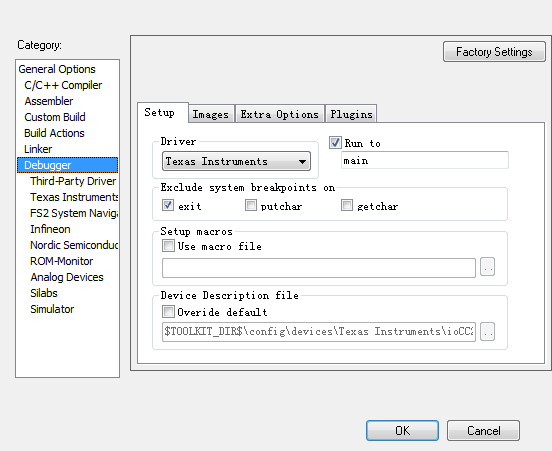
<2>Configure the simulation device : Debugger - >Setup -> Driver
[4] Add code file
<1> In the menu bar, File -> New -> File to create a blank file.
<2> Save the file to the specified location by executing the File -> Save command.
<3> Right-click on the project in " Workspace " and select Add -> Add File... Command to add the code file to the project.
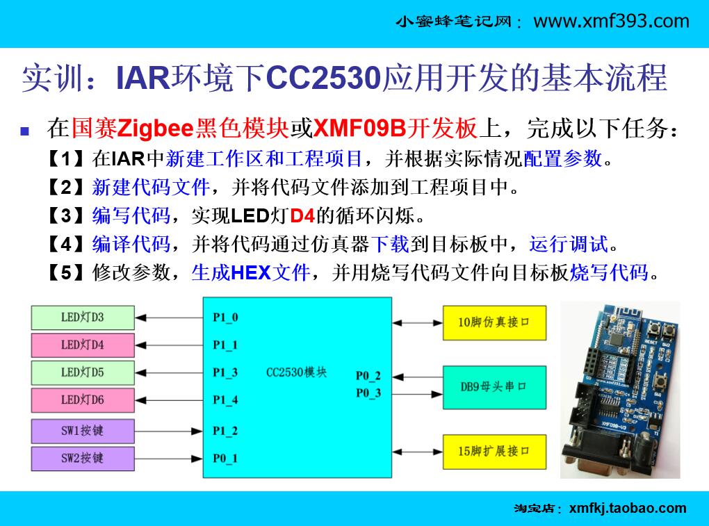
[5] Write the code in the code file
<please refer to the courseware or other technical notes for the marquee code>
[6] Compile the code
in the menu bar, Project -> Complie
or click the tool button in the toolbar.
Note: Only programs without syntax errors can be compiled.
[7] Simulation debugging
<1> Connect the emulator SmartRF4EB to the target board correctly: the triangle arrow on the cable is aligned with the white triangle arrow on the target board.
<2>In the menu bar, Project -> Download and Debug, Or click the " green triangle " button in the toolbar.

<3>Enter the simulation debugging environment.

At this point, you're done, you can debug at will.
[Attachment]: The source code of the LED light flashing.
#include "ioCC2530.h"

#define D4  P1_1

void Delay(unsigned int t)
{
  while(t--);
}

void Init_Port()
{
  P1SEL &= ~0x02;
  P1DIR |= 0x02;
}
void main()
{
  Init_Port();
  while(1)
  {
    D4 = 1;
    Delay(60000);
    D4 = 0;
    Delay(60000);
  }
}