Series of articles catalog
Base element 1.
The circuit design 3.PCB design 4. The welding element 6. programming 9. testing standards
Article Directory
- Preface
- 1. To be good at work, you must first sharpen your tools
- 2. Manual soldering steps of SMD components (electric soldering iron)
- 3. Manual soldering steps of SMD components (hot air gun)
- Four, manual welding summary
- 5. Small batch (100 to 1000 sets recommended)
Preface
For those who can’t find the direction of struggle after graduating from university (updated from time to time every week)
embedded system designer exam
1. To be good at work, you must first sharpen your tools
1. Electric soldering iron
Hand-soldering components, this is definitely indispensable. I recommend the tip of the soldering iron to everyone, because when soldering a chip with dense pins, it can accurately and conveniently solder a certain pin or a few pins (PS: I thought it was like this in the early days) , I found out that the cutter head is better after I got used to it!). An adjustable thermostat electric soldering iron is your best choice. It is best to have a digital display (the temperature can be adjusted and the temperature can be stabilized, and there are two types of single-handle temperature control and soldering station). It should be noted that the above internal heating type and external heating type usually do not have a power switch, and it is heated when it is plugged in, and the power is turned off when it needs to be cooled.

As the saying goes, a good horse needs a good saddle. Then the soldering iron head is the saddle of this horse (soldering iron). The selection of the soldering iron tip is based on the contact surface of the object to be welded. For example, for ordinary plug-in components, we mostly use horseshoe heads (large contact surface); small patch components can be pointed or bent (dense component welding); for conventional chips, knife heads (convenient drag welding) can be used. Of course, the more advanced DIY gameplay is to polish out the unique shape of the soldering iron tip according to your own needs.

We can't just use the newly bought soldering iron. We need to tin the new soldering iron for the first time.
2. Solder wire
A good solder wire is also very important for SMD soldering. If possible, use thin solder wires as much as possible when soldering SMD components, so that it is easy to control the amount of tin supplied, so that there is no waste of solder and the trouble of sucking tin. Chinese name: solder wire, solder wire, tin wire, tin wire, English name: solderwire, solder wire is composed of tin alloy and additives. The alloy components are divided into tin-lead and lead-free additives and are evenly poured into the tin alloy. Location. Different types of solder wire additives are also different, the auxiliary part is to improve the auxiliary heat conduction of the solder wire during the welding process, remove oxidation, reduce the surface tension of the material to be welded, remove the surface oil of the material to be welded, and increase the welding area. The characteristic of solder wire is a tin alloy wire with a certain length and diameter, which can be used in conjunction with an electric soldering iron or laser in the welding of electronic original devices.

The difference between lead-free and lead-free
solder wire : 1. The difference between lead-free and lead-free solder wire is only the difference in content.
2. Lead-containing solder wire needs to be artificially added with lead. The currently known best soldering ratio is tin-lead solder wire (national standard: tin content 63%, lead content 37%).
3. Lead-free solder wire also contains very little lead, and there is currently no completely pure metal product. Usually lead-free solder wire is called lead-free solder wire. Lead-free does not mean that there is no lead at all. Lead-free means that the lead content is relatively low, which can be roughly regarded as lead-free. The EU defines lead-free standard as: lead content< 1000PPm. Considering the possibility of further contamination during welding and subsequent work, in order to ensure that the customer's finished product meets the EU standards, the lead content of the general solder wire will be much lower than this standard.
4. Both lead-containing and lead-free solder wires will corrode the tip of the soldering iron, because the lead-free soldering temperature is higher than that of leaded solder wire, and the alloy composition is different, lead-free solder wire is more likely to corrode the soldering iron, due to lead-free requirements It is recommended to use lead-free special electric soldering iron when soldering lead-free tin wire.
3. Tweezers
The main function of the tweezers is to facilitate the clamping and placement of SMD components. For example, when soldering SMD resistors, the tweezers can be used to clamp the resistors and place them on the circuit board for soldering. The tweezers require a pointed and flat front end to facilitate clamping of the components. In addition, for some chips that need to prevent static electricity, anti-static tweezers are needed.

Anti-static tweezers are also called semiconductor tweezers, conductive tweezers, which can prevent static electricity. They are made of a mixture of carbon fiber and special plastics and have good elasticity. It is light and durable in use, does not fall ash, is resistant to acid and alkali, and is resistant to high temperatures. It can prevent traditional anti-static tweezers from contaminating products due to carbon black. It is suitable for the production and use of precision electronic components such as semiconductors and ICs, and its special use.
Anti-static tweezers are made of special conductive plastic materials, with good elasticity, lightness in use and static discharge characteristics, and are suitable for the processing and installation of static-sensitive components. Surface resistance: 1000KΩ—100000MΩ.
Anti-static tweezers are suitable for the production of precision electronic components, semiconductors and computer heads. If you use anti-static tweezers made of a mixture of carbon fiber and special plastics, they will not drop ash, are resistant to acids and alkalis, and are resistant to high temperatures, which can prevent traditional anti-static tweezers from contaminating products due to carbon black.
4. Suction tape
When soldering SMD components, it is easy to have too much tin. Especially when soldering densely multi-pin SMD chips, it is easy to cause the two adjacent pins or even multiple pins of the chip to be short-circuited by the solder. At this time, the traditional solder suction device does not work, this time you need a braided solder suction tape.

5. Rosin

Rosin is the most commonly used flux during soldering, because it can precipitate oxides in the solder, protect the solder from oxidation, and increase the fluidity of the solder.
When soldering in-line components, if the components are rusty, they should be scratched first, then put them on the rosin and iron them with a soldering iron, and then tin. When soldering SMD components, rosin can also be used as a tin suction tape with copper wire in addition to the soldering function.
6. Solder paste
Solder paste can be used when soldering iron parts that are difficult to tin. It can remove oxides on the metal surface and is corrosive.

When soldering SMD components, it can sometimes be used to "eat" the solder, so that the solder joints are bright and firm.
7. Hot air gun

The hot air gun is a tool that uses the hot air blown from the gun core to weld and disassemble the components. The process requirements for its use are relatively high. Hot air guns can be used from removing or installing small components to large integrated circuits. In different occasions, there are special requirements for the temperature and air volume of the hot air gun. If the temperature is too low, it will cause false soldering of the components, and if the temperature is too high, the components and circuit boards will be damaged. Excessive air volume will blow away small components. For ordinary patch welding, the hot air gun is not necessary, so I won't describe it in detail here.
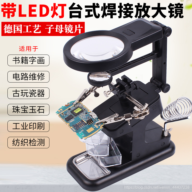
8. Magnifying glass

For some SMD chips with very small and dense pins, after soldering, you need to check whether the pins are soldered properly and whether there is a short circuit. At this time, it is very laborious to use the human eye, so you can use a magnifying glass to easily and reliably view each The soldering condition of the pins.
9. Washing water

When using rosin as a flux, it is easy to leave excess rosin on the circuit board. For the sake of beauty, at this time, you can wipe the residual rosin on the circuit board with washing water.
10. Other
In addition to the above-mentioned other common tools needed for patch welding, there are some such as sponge, washing water, hard brush, glue and so on.
2. Manual soldering steps of SMD components (electric soldering iron)
The source of the original text
After understanding the patch soldering tools, now the soldering steps are described in detail.
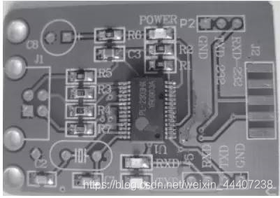
1. Clean and fix PCB (printed circuit board)
Before soldering, check the PCB to be soldered to ensure that it is clean. The oily fingerprints and oxides on the surface should be removed so as not to affect the tin. When soldering the PCB by hand, if conditions permit, you can use a soldering station or the like to fix it to facilitate soldering. Generally, it is good to fix it by hand. It is worth noting that your fingers should not touch the pads on the PCB and affect the soldering.
A clean circuit board

2. Fixed SMD components
The fixation of SMD components is very important. According to the number of pins of the patch component, the fixing method can be roughly divided into two types-single-leg fixing method and multi-leg fixing method. For SMD components with a small number of pins (generally 2-5), such as resistors, capacitors, diodes, triodes, etc., a single-pin fixing method is generally used. That is, tin on one of the pads on the board first.

Then hold the component with tweezers in your left hand and place it in the mounting position and lightly hold it against the circuit board. Hold the soldering iron in your right hand near the tinned pad and melt the solder. After soldering the pin

to a pad, the component will not move. At this time, the tweezers Can be loosened. For SMD chips with many pins and multi-sided distribution, it is difficult to fix the chip with a single pin. In this case, it needs to be fixed with multiple pins. Generally, you can use the method of

fixing the pins, that is, welding and fixing a pin and then the tube The pin opposite to the pin is welded and fixed, so as to achieve the purpose of fixing the entire chip. It should be noted that for chips with many and dense pins, precise pin alignment to the pads is especially important, and should be checked carefully, because the quality of soldering is determined by this premise.
It is worth emphasizing that the pin of the chip must be judged correctly. For example, sometimes we fix the chip carefully and even complete the soldering. During inspection, we find that the pin corresponds to the error-the pin that is not the first pin is used as the first pin to solder! Regret too much! Therefore, these meticulous preliminary work must not be sloppy.
3. Solder the remaining pins
After the components are fixed, the remaining pins should be soldered. For components with few pins, you can hold the soldering tin in your left hand and the soldering iron in your right hand, and then spot solder them in sequence. For chips with many and dense pins, in addition to spot welding, drag soldering can be used, that is, put enough tin on one pin and then use a soldering iron to melt the solder onto the remaining pins on that side. The molten solder can be Flow, so sometimes the board can be properly tilted to get rid of excess solder.

It is worth noting that, regardless of spot welding or drag welding, it is easy to cause adjacent pins to be short-circuited by tin. Don't worry about this, because it can be solved later. What needs to be concerned is that all the pins are well connected to the pads, and there is no virtual soldering.

4. Remove excess solder
在步骤3 中提到焊接时所造成的管脚短路现象,现在来说下如何处理掉这多余的焊锡。
一般而言,可以拿前文所说的吸锡带将多余的焊锡吸掉。吸锡带的使用方法很简单,向吸锡带加入适量助焊剂(如松香)然后紧贴焊盘,用干净的烙铁头放在吸锡带上,待吸锡带被加热到要吸附焊盘上的焊锡融化后,慢慢的从焊盘的一端向另一端轻压拖拉,焊锡即被吸入带中。应当注意的是吸锡结束后,应将烙铁头与吸上了锡的吸锡带同时撤离焊盘,此时如果吸锡带粘在焊盘上,千万不要用力拉吸锡带,而是再向吸锡带上加助焊剂或重新用烙铁头加热后再轻拉吸锡带使其顺利脱离焊盘并且要防止烫坏周围元器件。如果没有市场上所卖的专用吸锡带,可以采用电线中的细铜丝来自制吸锡带。

自制的方法如下:将电线的外皮剥去之后,露出其里面的细铜丝,此时用烙铁熔化一些松香在铜丝上就可以了。清除多余的焊锡之后的效果见下图。此外,如果对焊接结果不满意,可以重复使用吸锡带清除焊锡,再次焊接元件。
5. 清洗焊接的地方
焊接和清除多余的焊锡之后,芯片基本上就算焊接好了。但是由于使用松香助焊和吸锡带吸锡的缘故,板上芯片管脚的周围残留了一些松香。虽然并不影响芯片工作和正常使用,但不美观,而且有可能造成检查时不方便。因为有必要对这些残余物进行清理。常用的清理方法可以用洗板水,在这里,采用了酒精清洗,清洗工具可以用棉签,也可以用镊子夹着卫生纸之类进行。

清洗擦除时应该注意的是酒精要适量,其浓度最好较高,以快速溶解松香之类的残留物。其次,擦除的力道要控制好,不能太大,以免擦伤阻焊层以及伤到芯片管脚等。清洗完毕的效果见下图。此时可以用烙铁或者热风枪对酒精擦洗位置进行适当加热以让残余酒精快速挥发。至此,芯片的焊接就算结束了。

三、贴片元件的手工焊接步骤(热风枪)
1.准备工作
1、打开热风枪,把风量,温度调到适当位置:用手感觉风筒风量与温度;观察风筒有无风量用温度不稳定现象。
2、观察风筒内部呈微红状态。防止风筒内过热。
3、用纸观察热量分布情况。找出温度中心。
4、用最低温度吹一个电阻,记住最能吹下该电阻的最低温度旋扭的位置。
5、调节风量旋扭,让风量指示的钢球在中间位置。
6、调节温度控制,让温度指示在380℃左右。
注意:短时间不使用热风枪时,要使其进入休眠状态(手柄上有休眠开关的按一下开关即可,手柄上无开关的,风嘴向下为工作,风嘴向上为休眠),超过5分钟不工作时要把热风枪关闭。
2. 使用热风枪拆焊扁平封装IC
①.拆扁平封装IC步骤:
1、拆下元件之前要看清IC方向,重装时不要放反。
2、观察IC旁边及正背面有无怕热器件(如液晶,塑料元件,带封胶的BGA IC等)如有要用屏蔽罩之类的物品把他们盖好。
3、在要拆的IC引脚上加适当的松香,可以使拆下元件后的PCB板焊盘光滑,否则会起毛刺,重新焊接时不容易对位。
4、把调整好的热风枪在距元件周围20平方厘米左右的面积进行均匀预热(风嘴距PCB板1CM左右,在预热位置较快速度移动,PCB板上温度不超过130-160℃)
1)除PCB上的潮气,避免返修时出现“起泡”。
2)避免由于PCB板单面(上方)急剧受热而产生的上下温差过大所导致PCB焊盘间的应力翘曲和变形。
3)减小由于PCB板上方加热时焊接区内零件的热冲击。
4)避免旁边的IC由于受热不均而脱焊翘起。
5)线路板和元件加热:热风枪风嘴距IC 1CM左右距离,在沿IC边缘慢速均匀移动,用镊子轻轻夹住IC对角线部位。
6)如果焊点已经加热至熔点,拿镊子的手就会在第一时间感觉到,一定等到IC引脚上的焊锡全部都熔化后再通过“零作用力” 小心地将元件从板上垂直拎起,这样能避免将PCB或IC损坏,也可避免PCB板留下的焊锡短路。加热控制是返修的一个关键因素,焊料必须完全熔化,以免在取走元件时损伤焊盘。与此同时,还要防止板子加热过度,不应该因加热而造成板子扭曲。(如:有条件的可选择140℃-160℃做预热和低部加温补热。拆IC的整个过程不超过250秒)
7)取下IC后观察PCB板上的焊点是否短路,如果有短路现象,可用热风枪重新对其进行加热,待短路处焊锡熔化后,用镊子顺着短路处轻轻划一下,焊锡自然分开。尽量不要用烙铁处理,因为烙铁会把PCB板上的焊锡带走,PCB板上的焊锡少了,会增加虚焊的可能性。而小引脚的焊盘补锡不容易。
②.装扁平IC步骤
1、观察要装的IC引脚是否平整,如果有IC引脚焊锡短路,用吸锡线处理;如果IC引脚不平,将其放在一个平板上,用平整的镊子背压平;如果IC引脚不正,可用手术刀将其歪的部位修正。
2、把焊盘上放适量的助焊剂,过多加热时会把IC漂走,过少起不到应有作用。并对周围的怕热元件进行覆盖保护。
3、将扁平IC按原来的方向放在焊盘上,把IC引脚与PCB板引脚位置对齐,对位时眼睛要垂直向下观察,四面引脚都要对齐,视觉上感觉四面引脚长度一致,引脚平直没歪斜现象。可利用松香遇热的粘着现象粘住IC。
4、用热风枪对IC进行预热及加热程序,注意整个过程热风枪不能停止移动(如果停止移动,会造成局部温升过高而损坏),边加热边注意观察IC,如果发现IC 有移动现象,要在不停止加热的情况下用镊子轻轻地把它调正。如果没有位移现象,只要IC引脚下的焊锡都熔化了,要在第一时间发现(如果焊锡熔化了会发现 IC有轻微下沉,松香有轻烟,焊锡发亮等现象,也可用镊子轻轻碰IC旁边的小元件,如果旁边的小元件有活动,就说明IC引脚下的焊锡也临近熔化了。)并立即停止加热。因为热风枪所设置的温度比较高,IC及PCB板上的温度是持续增长的,如果不能及早发现,温升过高会损坏IC或PCB板。所以加热的时间一定不能过长。
5、等PCB板冷却后,用酒精(或洗板水)清洗并吹干焊接点。检查是否虚焊和短路。
6、如果有虚焊情况,可用烙铁一根一根引脚的加焊或用热风枪把IC拆掉重新焊接;如果有短路现象,可用潮湿的耐热海棉把烙铁头擦干净后,蘸点松香顺着短路处引脚轻轻划过,可带走短路处的焊锡。或用吸锡线处理:用镊子挑出四根吸锡线蘸少量松香,放在短路处,用烙铁轻轻压在吸锡线上,短路处的焊锡就会熔化粘在吸锡线上,清除短路。
另:也可以用电烙铁焊接IC,把IC与焊盘对位后,用烙铁蘸松香,顺着IC引脚边缘依次轻轻划过即可;如果IC的引脚间距较大,也可以加松香,用烙铁带锡球滚过所有的引脚的方法进行焊接。
3.使用热风枪拆焊怕热元件
①.拆元件
一般如排线夹子,内联座,插座,SIM卡座,电池触片,尾插等塑料元件受热容易变形,如果确实坏了,那不妨象拆焊普通IC那样拆掉就行了,如果想拆下来还要保持完好,需要慎重处理。有一种旋转风热风枪风量、热量均匀,一般不会吹坏塑料元件。如果用普通风枪,可考虑把PCB板放在桌边上,用风枪从下边向上加热那个元件的正背面,通过PCB板把热传到上面,待焊锡熔化即可取下;还可以把怕热元件上面盖一个同等大的废旧芯片,然后用风枪对芯片边缘加热,待下面的焊锡熔化后即可取下塑料元件。
②.装元件
整理好PCB板上的焊盘,把元件引脚上蘸适量助焊剂放在离焊盘较近的旁边,为了让其也受一点热。用热风枪加热PCB板,待板上的焊锡发亮,说明已熔化,迅速把元件准确放在焊盘上,这时风枪不能停止移动加热,在短时间内用镊子把元件调整对位,马上撤离风枪即可。这一方法也适用于安装功放及散热面积较大的电源 IC等。有些器件可方便的使用烙铁焊接(如SIM卡座),就不要使用风枪了。
4.拆焊阻容三极管等小元件
①.拆元件
1、在元件上加适量松香,用镊子轻轻夹住元件,用热风枪对小元件均匀移动加热(同拆焊IC),拿镊子的手感觉到焊锡已经熔化,即可取下元件。
2、用烙铁在元件上适量加一些焊锡,以焊锡覆盖到元件两边的焊点为准,把烙铁尖平放在元件侧边,使新加的焊锡呈溶化状态,即可取下元件了。如果元件较大,可在元件焊点上多加些锡,用镊子夹住元件,用烙铁快速在两个焊点上依次加热,直到两个焊点都呈溶化状态,即可取下。
②.装元件
1、在元件上加适量松香,用镊子轻轻夹住元件,使元件对准焊点,用热风枪对小元件均匀移动加热,待元件下面的焊锡熔化,再松开镊子。(也可把元件放好并对其加热,待焊锡溶化再用镊子碰一碰元件,使其对位即可。)
2、用镊子轻轻夹住元件,用烙铁在元件的各个引脚上点一下,即可焊好。如果焊点上的焊锡较少,可在烙铁尖上点一个小锡珠,加在元件的引脚上即可。
5.使用热风枪拆焊屏蔽罩
①.拆屏蔽罩
用夹具夹住PCB板,镊子夹住屏蔽罩,用热风枪对整个屏蔽罩加热,焊锡溶化后垂直将其拎起。因为拆屏蔽罩需要温度较高,PCB板上其它元件也会松动,取下屏蔽罩时主板不能有活动,以免把板上的元件震动移位,取下屏蔽罩时要垂直拎起,以免把屏蔽罩内的元件碰移位。也可以先掀起屏蔽罩的三个边,待冷却后再来回折几下,折断最后一个边取下屏蔽罩。
②.装屏蔽罩
把屏蔽罩放在PCB板上,用风枪顺着四周加热,待焊锡熔化即可。也可以用烙铁选几个点焊在PCB板上。
6.加焊虚焊元件:
①.用风枪加焊
在PCB板需要加焊的部位上加少许松香,用风枪进行均匀加热,直到所加焊部位的焊锡溶化即可,也可以在焊锡熔化状态用镊子轻轻碰一碰怀疑虚焊的元件,加强加焊效果。
②.用电烙铁加焊
用于少量元件的加焊,如果是加焊IC,可在IC引脚上加少量松香,用光洁的烙铁头顺着引脚一条一条依次加焊即可。一定要擦干净烙铁头上的残锡,否则会使引脚短路。如果是加焊电阻、三极管等小元件,直接用烙铁尖蘸点松香,焊一下元件引脚即可。有时为了增加焊接强度,也可给元件引脚补一点点焊锡。
四、手工焊总结
In summary, soldering SMD components is a process of fixing-welding-cleaning in general.
The fixing of the components is a prerequisite for good or bad soldering. You must be patient to ensure that each pin and its corresponding pad are aligned accurately. When soldering multi-pin chips, don’t worry about the pins being short-circuited by the solder. You can use a suction tape for soldering or just use a soldering iron to remove the excess solder by using the flux of the solder after melting. Of course, the mastery of these skills requires practice. Due to space limitations, only one type of multi-pin chip is demonstrated in the article. For many other types of multi-pin SMD chips, the pin density, mechanical strength, quantity, etc. are correspondingly different under different circumstances. The welding method is basically the same, but the details are slightly different. Therefore, if you want to become a master of soldering SMD components, you need to practice more to improve your proficiency. If conditions permit, you can be more skilled if you have old circuit boards and old chips.
5. Small batch (100 to 1000 sets recommended)
Buy a small SMT placement machine for about 1500 yuan, and an SMT manual printing pad about 300 yuan.
