Hello, everyone, I am Xiaozheng, a student majoring in automation. Recently, I am learning to use opencv for environmental monitoring. I need to transmit the acquired data to stm32 through the communication protocol. I chose to use the wifi module for wireless communication. Next, I will share with you the process from getting started to mastering the wifi module.
Here is the link to the following serial debugging assistant and network connection assistant Baidu Netdisk: https://pan.baidu.com/s/1Te9vJPM5Ct5WMIhA5pksDA
extraction code: cr77
- 1. Common uses of WiFi module
- 2. WiFi module working mode
- 3. Use the serial port debugging assistant to verify
1. Common uses of WiFi module:
Main uses:
(1) Wireless communication between mobile phone and single-chip microcomputer
(2) Interconnection communication between single-chip microcomputer and single-chip microcomputer (dual-computer communication)
(3) Internet of things application (upload data to the server, and then through mobile phone or other Platform remote viewing and remote control)
2. WiFi module working mode:
Working mode of WIFI module· AP mode (routing mode, such as our mobile phone as a hotspot to connect to others)
· STA mode (as a wireless access point, such as our mobile phone to connect to WIFI)
· STA + AP coexistence
3. Use the serial debugging assistant to verify:
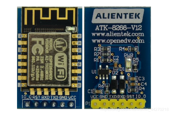
Connect the wifi module to the computer with the help of USB to TTL (the other two pins do not need to be connected), the corresponding interface is as follows:

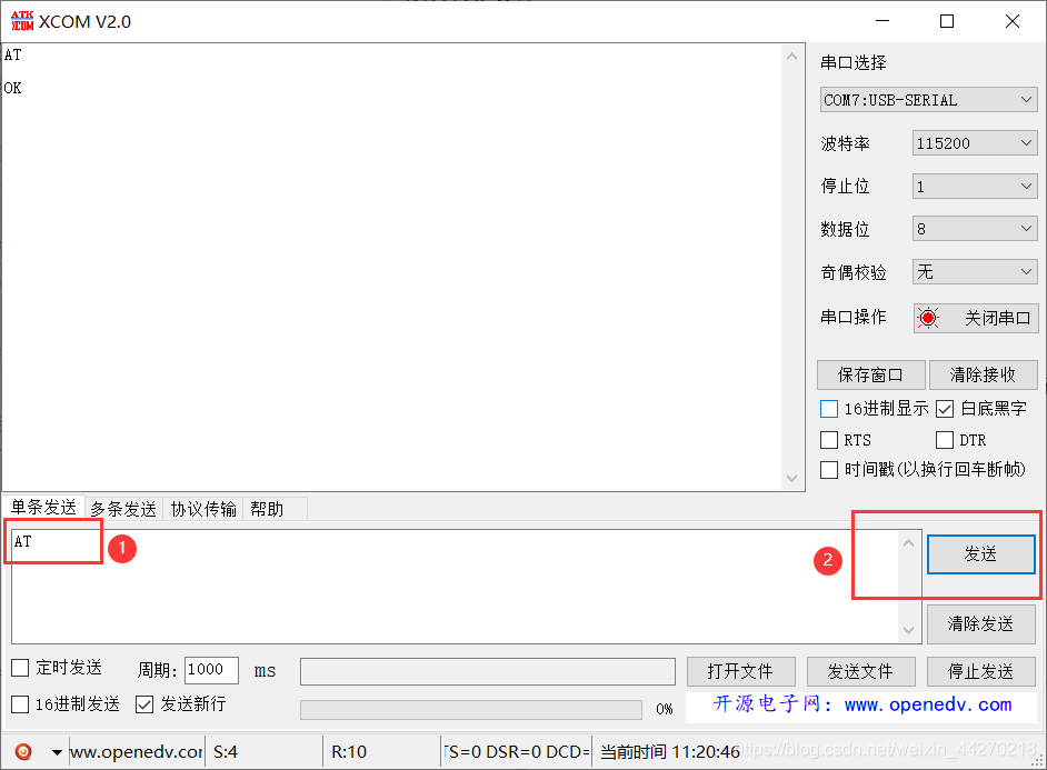
Then open the serial port debugging assistant to send AT commands, and the corresponding baud rate is generally 115200.
-
(1) We first send an instruction: AT, if it returns OK, it means that the WIFI connection is normal.
-
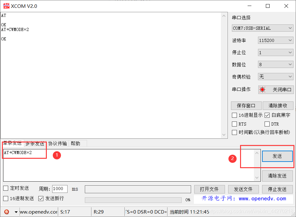
(2) Next, send the command: AT+CWMODE=2, which means: set the working mode of the WIFI module to AP mode.
-
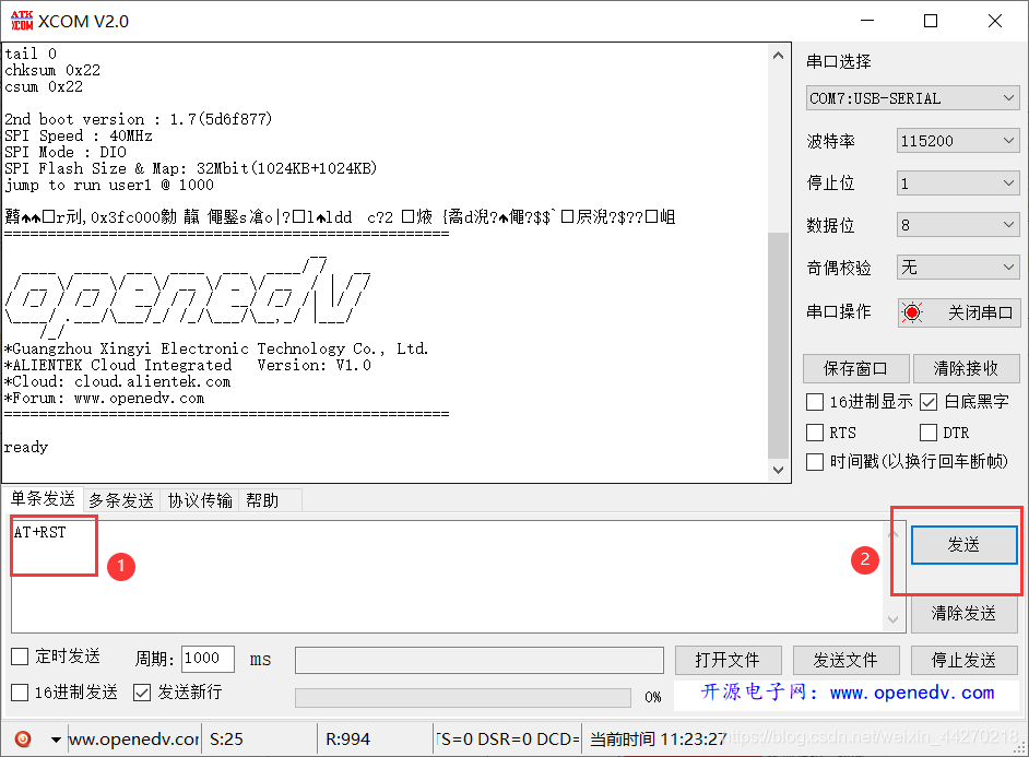
(3) Restart the WIFI module and send the command: AT+RST
-
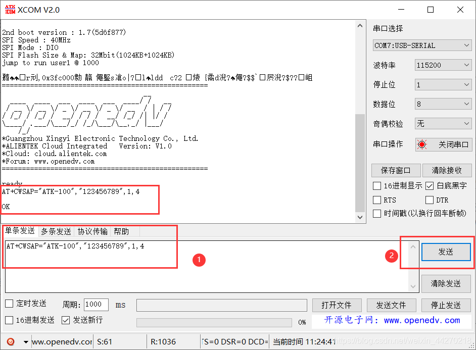
(4) Set the account and password of the WIFI module and the security encryption type. You can set it once. This configuration can still be saved after power off. Send the command: AT+CWSAP="ATK-100","123456789",1,4
-
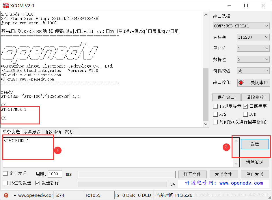
(5) Set the connection mode (0 is single connection, 1 is multiple connection), send command: AT+CIPMUX=1 (select multiple connection here)
-
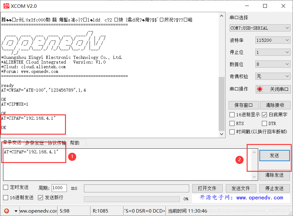
(6) Set the IP address and send the command: AT+CIPAP="192.168.4.1" (especially important!!!)
-
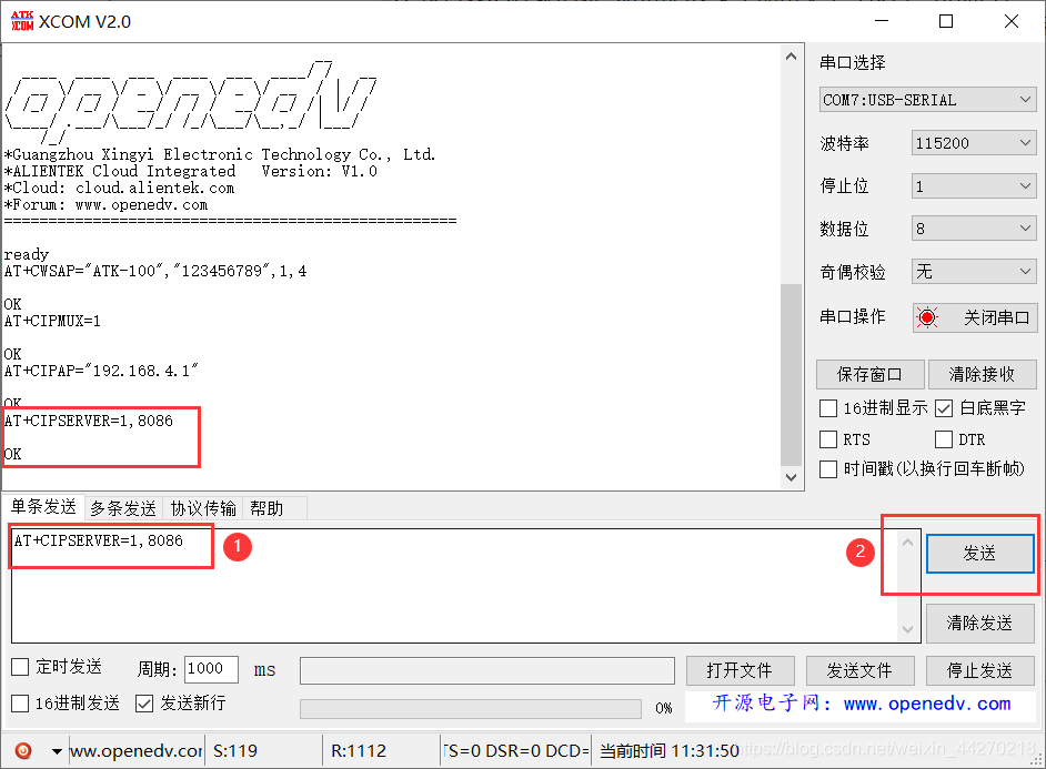
(7) Set the port number and send the command: AT+CIPSERVER=1,8086 (especially important!!!). At this step, the WIFI module can be used normally.
-
(8) Next, we need to use a mobile phone to connect to the WIFI we have set, and enter the wifi password: 123456789 (set above) to connect.
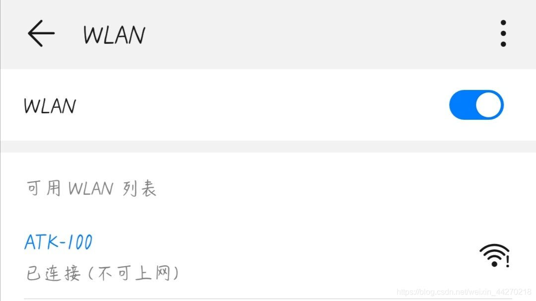
-
(9) Next, use the network debugging assistant provided for everyone above (the Android version and the Apple version are both in the compressed package!), open the network debugging assistant, click tcp client (TCP client), and set it as before Connect with the IP address and port number.
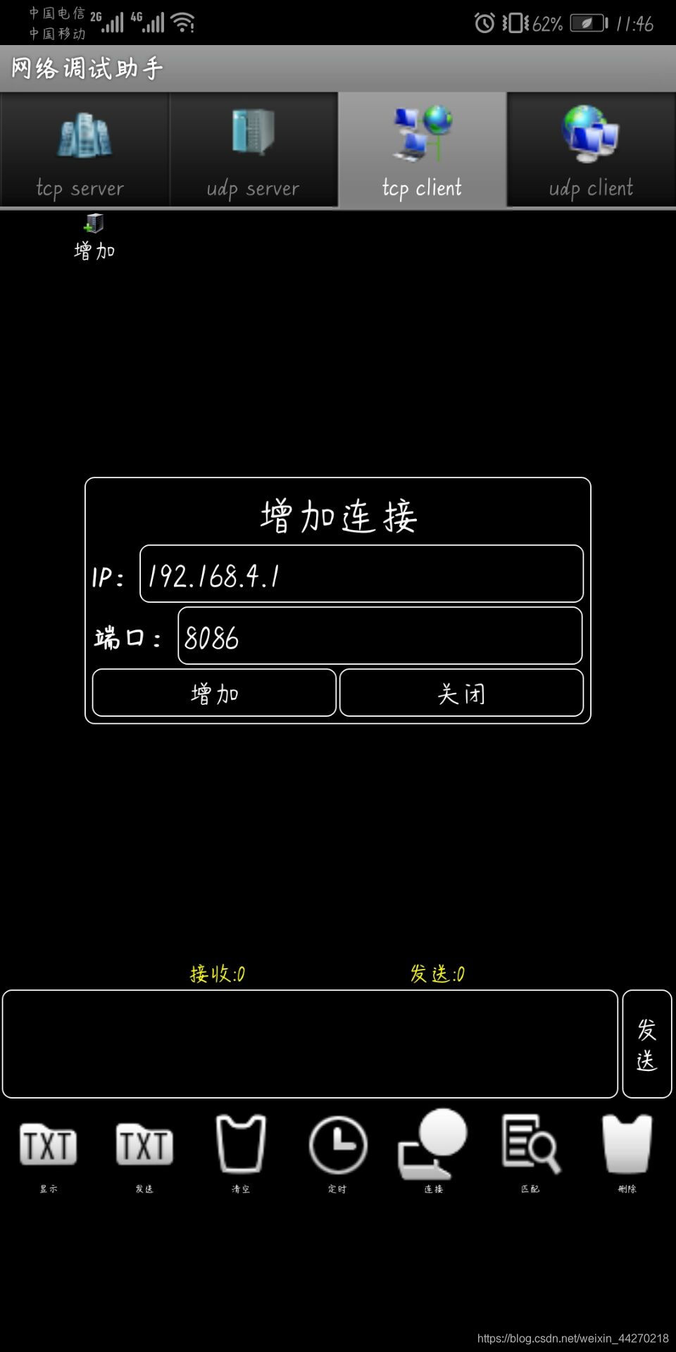
-
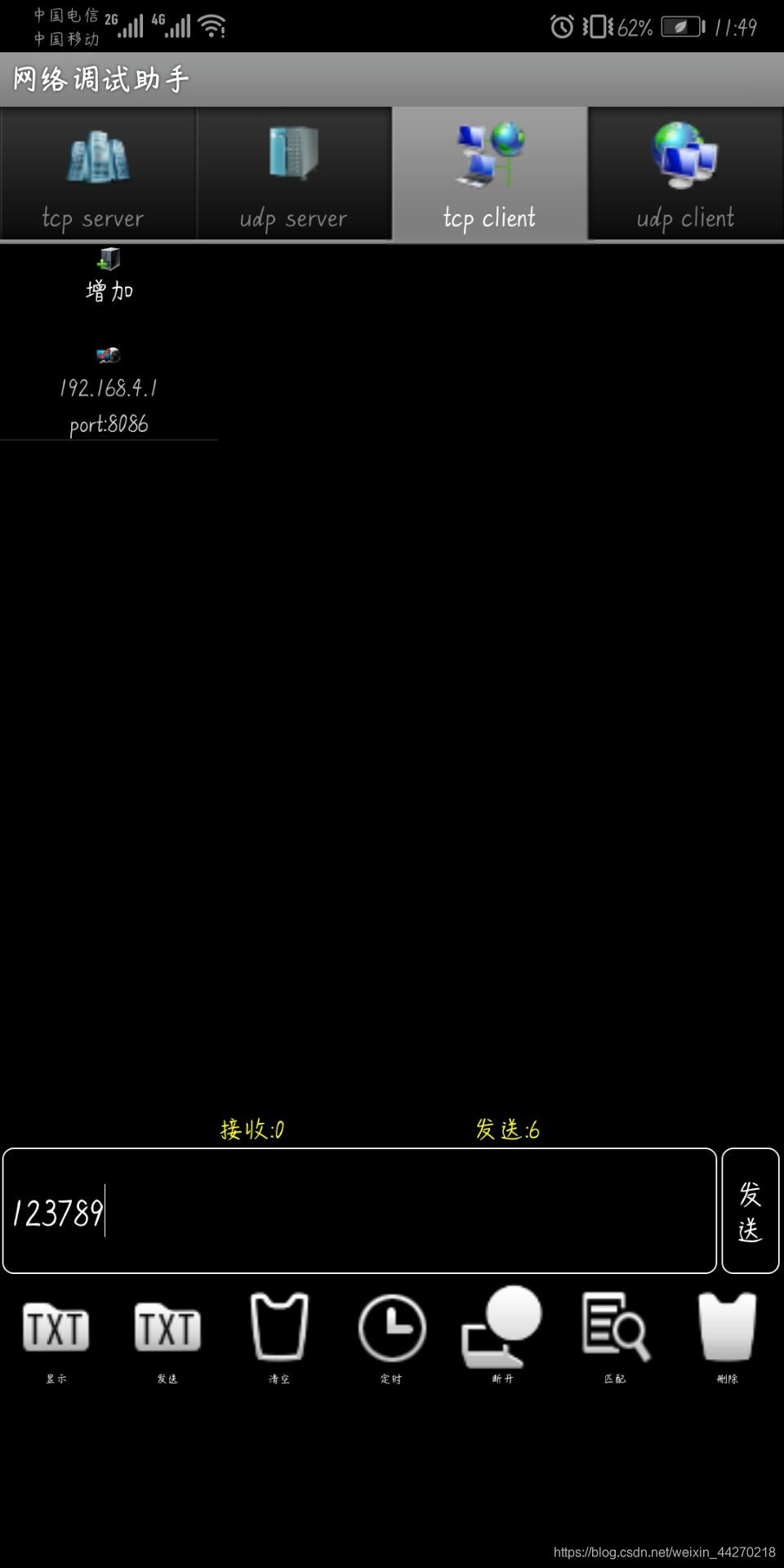
(10) The connection is successful

-
(11) The mobile phone sends information to the wifi module (here it is received by the serial port debugging assistant)
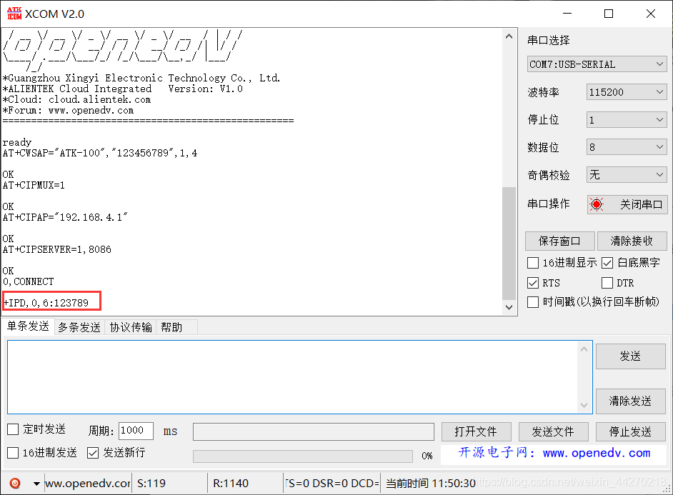
-
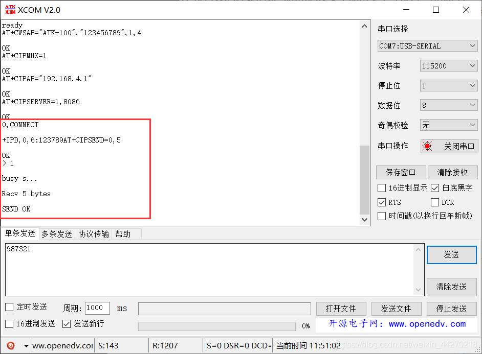
(12) The WIFI module sends information to the mobile phone. Here we need to pay attention that this command must be sent first when the WIFI module sends data: AT+CIPSEND=0,25 (where 25 is the number of bytes to be sent, one Chinese character occupies two One byte, an English symbol and letter, and a number each occupy one byte), and then send the command you want. For example: I send AT+CIPSEND=0,5, and then send 987321, the phone can only receive 98732, because I set to send 5 bytes.

At this point, we have verified that the AT command set is available through the serial debugging assistant, and can be used for some simple applications of the WiFi module. The next blog will explain the code of the WiFi module AP configuration, realize that the mobile phone can turn on or off the LED light through the WiFi module control, and then return the LED status to the mobile phone through the WiFi module.
If you think this article is helpful to you, don't forget to like it! Want to learn more about how to use STM32 microcontrollers and the use of various electronic modules, click one to follow!