Article Directory
Textbook use "programming language compiler principles" version of -3, Author: Chen Huo, Liu Chunlin and so on.
Use your own words to reproduce the sample questions on the textbook. If there are any shortcomings, please advise.
NFA: non-deterministic finite automata;
DFA: definite finite automata;
Formal to NFA
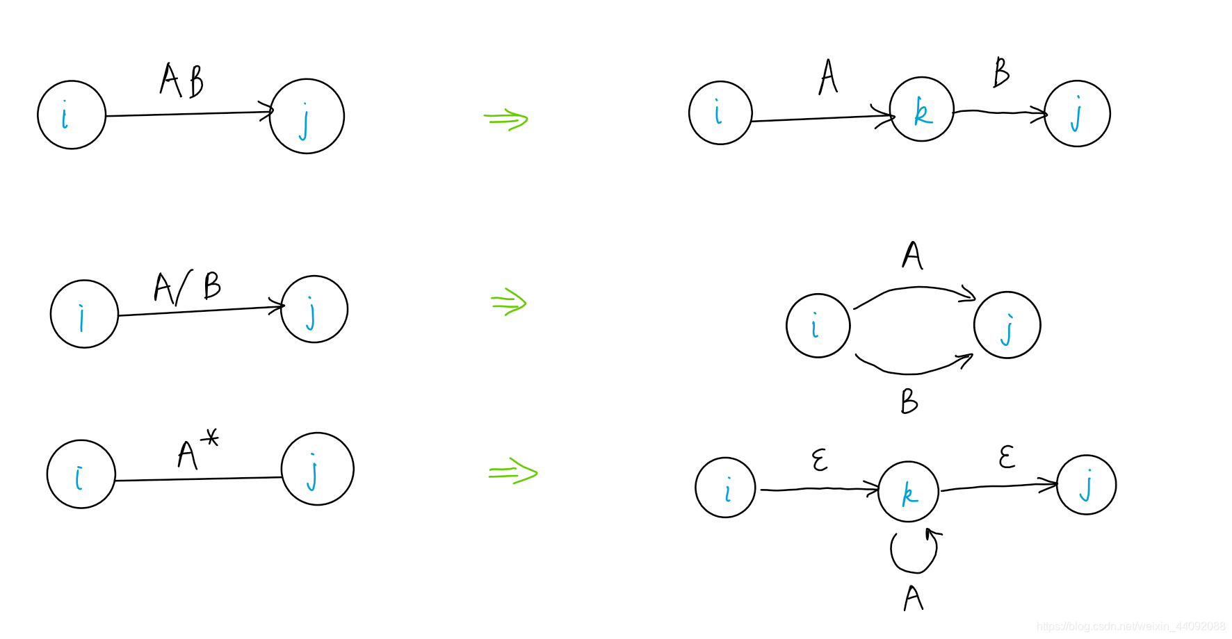
It's that simple. . .
NFA -> DFA
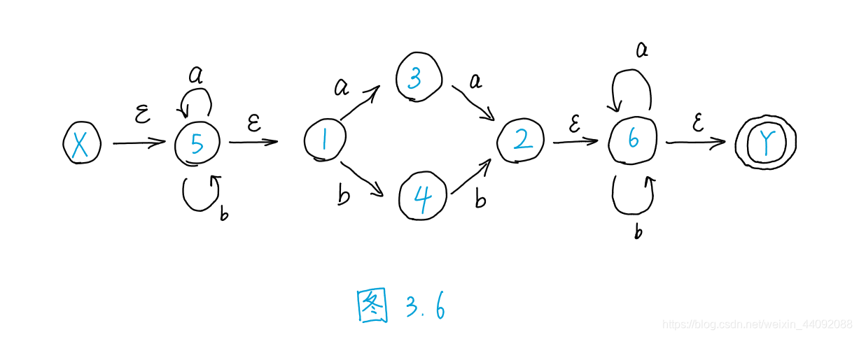
Figure 3.6 Non-deterministic finite automata
Involved in the textbook P49~P50 explainedSubset method——The method to determine NFA as DFA. (Explained below)
definition
- M : NFA
- M’ : The final NFA
- M’’: DFA
assumes that I is a subset of the state set of M', - ε_CLOSURE(I): A connected by ε arc connected component
I of the ε closure, including I per se, but also from any of a state of the element q can be reached by any article ε arc state q ' ;
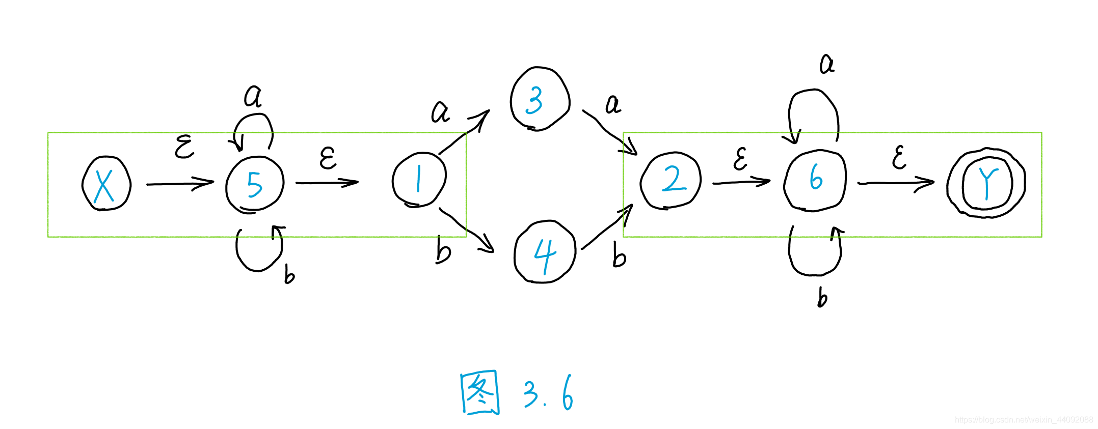
FIG. 3.6 Example : image ε_CLOSURE ( {X- } ) = {X, 5, 1} , ε_CLOSURE( {2} ) = {2, 6, Y} , which
is a connected component connected by ε arcs ; - I a: A connected by a arc connected component
I a = ε_CLOSURE (J), J in a state q ' is in any state from I, q by one a arc can reach a state, do not forget by any article ε arcs reaching Status;
Figure 3.6 Example : {5, 3, 1} a = {5, 3, 1, 2, 6, 7}, the
analysis process :
| Original state | State reached by arc a |
|---|---|
| 5 | 5 |
| 3 | 2 |
| 1 | 3 |
Get the state set: {5, 3, 2};
| Original state | State reached through ε arc |
|---|---|
| 5 | 1 |
| 3 | \ |
| 2 | 6, AND |
Finally, we get the state set: {5, 3, 1, 2, 6, 7};
note that each state, especially the final state, can be seen as having an ε arc connecting itself, so the final state can only read ε, Others cannot be read. Some of the above state sets contain the final state Y, which is reached by the previous state through the ε arc.
Example 3.3 Convert NFA to DFA
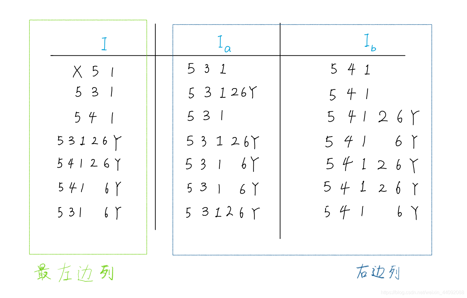
The normal expression (a|b) * (aa|bb)(a|b) * corresponds to the NFA shown in Figure 3.6, where X is the initial state and Y is the final state. Follow the above process (Subset method) The constructed state transition matrix is shown in Table 3.3
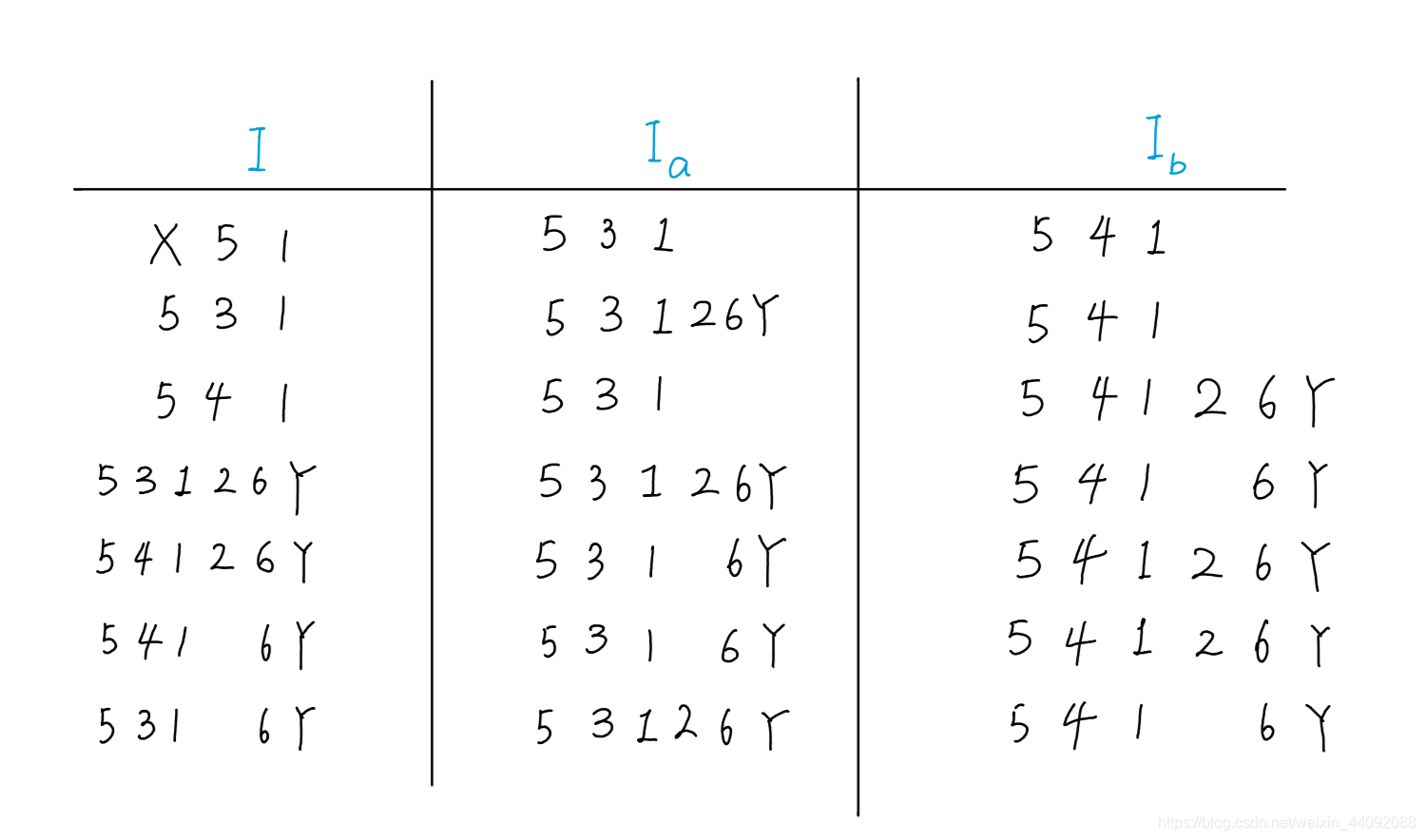
Table 3.3 The state transition matrix corresponding to the normal form in Example 3.3
Construction process
The ε closure of the initial state X, namely ε_CLOSURE( {X} ), is now marked as I and placed in the first column of the first row to find I a , I b , which will appear in the right column (except for the leftmost column) The state set that does not appear in the leftmost column), but the state set that does not appear in the leftmost column, add it to the leftmost column, and repeat the operation until all state sets appearing in the right column have appeared in the leftmost column.
Rename
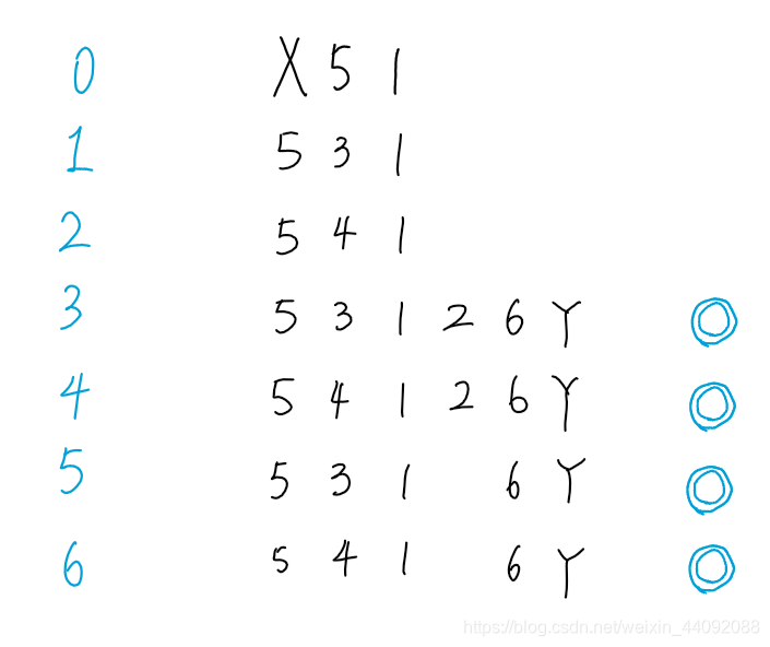
Rename all the state subsets in Table 3.3. The new state containing the original final state Y is also the final state. Mark the double circle to get the state transition matrix listed in Table 3.4 ; Table 3.4 renames the state subset
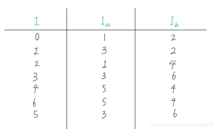
in Table 3.3 Named state transition matrix
Draw the corresponding state diagram from Table 3.4 (Figure 3.8):
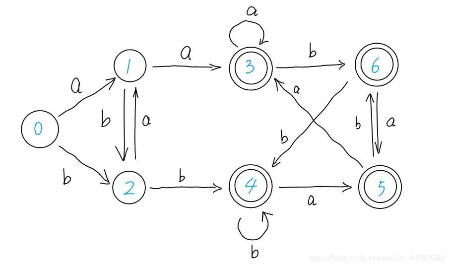
Figure 3.8 Unsimplified DFA
Example 3.6 Simplify DFA
Simplify the DFA shown in Figure 3.8;
first divide the state of M into two groups: the final state group and the non-final state group ;
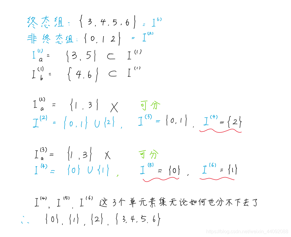
get the simplified image (Figure 3.5):
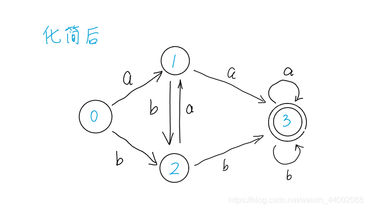
Figure 3.5 state transition diagram