
☞☞☞ Click to see more outstanding embedded blog ☜☜☜
☞☞☞ Click to see more outstanding industrial PLC blog ☜☜☜

Troubleshooting three-phase motor
- A three-phase motor Introduction
- Second, the three-phase motor terminal
- Third, the actual operation
- Four difference, triangular, and star-connected
- Fifth, the actual case
- Six three-phase asynchronous motor reversing control
- Seven, three-phase motor model
- Eight, model letters meaning
- Nine, the composition of the three-phase motor
- Ten, Speed Control
A three-phase motor Introduction
Refers to a three-phase motor when the motor phase stator windings (different by 120 electrical degrees), into the three-phase AC, will produce a rotating magnetic field, the rotating magnetic field cutting rotor winding, thereby generating an induced current in the rotor winding ( rotor winding passage is closed), the electromagnetic force of the rotating rotor carrying conductor in the magnetic field of the stator, thereby forming electromagnetic torque on the motor shaft, rotation of the drive motor, the motor rotational direction and the same direction of the rotating magnetic field.
Working principle: when a symmetrical three-phase AC into the three-phase stator winding, generates a synchronous speed n1 of the inner rotor and the stator along the circular space for clockwise rotation of the rotating magnetic field. Since n1 rotated at a rotational speed of the rotating magnetic field, when the rotor is stationary conductor starts, it will cut the conductor rotor rotating stator magnetic field generates an induced electromotive force (induced electromotive force direction is determined by the right hand). Since the ends of the rotor conductors are short-circuited shorted loop, under the influence of induced electromotive force is generated in the rotor conductor substantially coincides with the direction of the induced electromotive force induced current. Carrying conductor rotor by electromagnetic forces acting on the stator field (the direction of the force given by the left hand is determined). The electromagnetic force of the electromagnetic torque of the rotor shaft, the rotor rotates in the driving direction of the rotating magnetic field.
The above analysis can be summarized by the motor works as follows: When the three-phase stator windings of the motor (different by 120 degrees in electrical angle), into three phase AC power, generated a rotating magnetic field, the rotating magnetic field cutting rotor winding, whereby induced current in the rotor winding (rotor winding path is closed), the rotor carrying conductor of the magnetic field rotating in the stator to generate an electromagnetic force, so as to form an electromagnetic torque on the motor shaft, the drive motor rotates, and the rotational direction of the motor rotation the same magnetic field direction.
Second, the three-phase motor terminal

Third, the actual operation
1, star connection:
in fact, is to click on the coil end all together.
It is to U2, v2, w2 together.
2, the triangular connection
is end to end, u2 then w1, w2 then v1, v2 then u
Four difference, triangular, and star-connected
The motor coil by star connection is 220V. (Low voltage to reduce starting current)
motor winding is delta-connected by 380V.
Fifth, the actual case
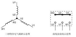
Phase stator windings of the three-phase asynchronous motor has two lead wires each phase winding heads. One called the head end, the other end is called the end. The first predetermined phase winding is expressed by D1 head end, the end denoted by D4; a second phase winding head end represented by D2, D5 indicated by the end; the first end of the third phase winding are represented by D3 and D6. The six first lead terminal into the terminal box, terminals D1 ~ D6 label the label, see (1).
Phase stator windings of the six end-phase stator windings may be connected in star or delta, star connection three-phase winding terminal is connected in parallel, i.e. D4, D5, D6 with a bar connected to three terminals together, and the three-phase windings, respectively, access to the head-end three-phase AC power, i.e. D1, D2, D3 respectively connected A, B, C phase power, as shown in (2).
Sucked and delta connection of the first phase winding is connected to the head end terminal D1 D6 of the third phase winding, and then connected with a power source; D2 of the second end of the first phase winding and the first terminal D4 is connected to phase windings , then access to the second power supply phase; D3 of the third phase winding head end and the terminal D5 of the second phase winding are connected, and then connected with the third power. I.e. at the terminal board terminals D1 and D6, D2 and D4, D3 and D5 are connected by copper, then access to three-phase power, respectively, as shown in (3).
In special cases: To reverse-phase stator windings may be reversed with the end of the first three-phase windings, for example three-phase winding terminal D4, D5, D6 as the first reverse side, and the D1, D2, D3 as a terminal but can not alone be the end of the first phase winding of a reversed, otherwise it will produce wiring errors. If a connection error occurs in the junction box, or the end of the first winding mistake, ranging from the motor can not start normally, resulting in a long time to start energizing current is too large, a serious heating of the motor, affecting the life, while burning of motor windings, or short the power supply.
Six three-phase asynchronous motor reversing control
The main electrical components: push switch 3, two contacts, a thermal overload, the fuse 3 is preferably applied to protect a three FireWire.
To achieve the motor reversing control, the sequence in which any two phases can be adjusted relative power (we call commutation), the V-phase is usually constant, the U-phase and W relative key, in order to ensure two contacts replacement operation can be surely when the phase sequence of the motor, the wiring should be so catchy wiring contactor consistent phasing the opening of the contactor. Due to the two-phase phase sequence reversed, it must ensure that the two KM coil is energized at the same time can not, otherwise serious phase fault occurs, and therefore must be taken interlock.
Forward start-up process
by pressing the start button SB2, contactor KM1 coil is energized, the auxiliary SB2 KM1 parallel normally open contact is closed, to ensure continuous power KMl coil, connected in series in the motor main contact KM1 continued closed circuit, continuous forward motor operation.
Stopping process
stop button SB1, KMl contactor coil power, the auxiliary contact KM1 is OFF SB2 in parallel, in order to ensure continued KMl energized coil, in series with the main contacts of the motor circuit KMl continuously disconnected, off motor stator, a motor stall.
Start reverse process
SB3 press the start button, contactor KM2 coil is energized, the auxiliary SB3 KM2 parallel normally open contact is closed, to ensure the continued energization coil KM2, KM2 tandem master contacts in the motor circuit closed sustained, continuous reverse motor operation. Phase asynchronous motor reversing contactor interlock control of three-phase asynchronous motor reversing control

Seven, three-phase motor model
TYPE: type (model).
TYPE: Chinese resolve to form, style, type, variety; expressed as a model in the motor.
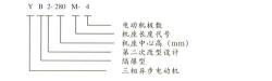
Model consists of four parts product code, the code specifications, special environmental code and add code and so on. They are arranged in the following order: product code - specification code - code-named special circumstances - add code.
Product code : a four bar type code sequence motors, motor characteristics of the code, number and design excitation mode code and so on. 1 type code is employed to characterize the various types of motor phonetic alphabet.
Extended Information:
In Y132M-4 7.5KW of the motor, for example, mean Y Y three-phase asynchronous motor, the motor 132 is a high 132MM center, M is a medium base, 4 represents a four pole motor.
In this type of motor, for example YH100L1-4, YH mean YH series high slip three-phase asynchronous motors, the motor 100 is a high center of 100MM, L is a lead plane seat, the code length of the core 1, four 4 pole motor.
There are many types of motor, so there are different models of motor, there is a shift YD, YEJ brake, three distinct frequency downconverts, etc. YVP motor.
Motor frame size: generally refers to the motor center. The motor model M, L, S, is the length of the cabinet. 2 is the length of the core. Shangyu Dongxing expertise geared motors, motors. Any questions can be asked and Kazakhstan.
Eight, model letters meaning
J——异步电动机; O——封闭; L——铝线缠组;
W——户外; Z——冶金起重; Q——高起动转轮;
D——多速; B——防爆; R一绕线式;
S——双鼠笼; K一—高速; H——高转差率。
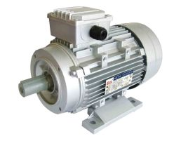
九、三相电机组成
三相异步电动机由固定的定子和旋转的转子两个基本部分组成,转子装在定子内腔里,借助轴承被支撑在两个端盖上。为了保证转子能在定子内自由转动,定子和转子之间必须有一间隙,称为气隙。电动机的气隙是一个非常重要的参数,其大小及对称性等对电动机的性能有很大影响。图2所示为三相笼型异步电动机的组成部件。

十、调速方式
变极数调速
这种调速方法是用改变定子绕组的接线方式来改变笼型电动机定子极对数达到调速目
的,特点如下:
1、具有较硬的机械特性,稳定性良好;
2、无转差损耗,效率高;
3、接线简单、控制方便、价格低;
4、有级调速,级差较大,不能获得平滑调速;
5、可以与调压调速、电磁转差离合器配合使用,获得较高效率的平滑
调速特性。
该方法适用于不需要无级调速的生产机械,如金属切削机床、升降机、起重设备、风机、水泵等。
变频调速
变频调速是改变电动机定子电源的频率,从而改变其同步转速的调速方法。变频调速系统主要设备是提供变频电源的变频器,变频器可分成交流-直流-交流变频器和交流-交流变频器两大类,国内大都使用交-直-交变频器。其特点:
1、效率高,调速过程中没有附加损耗;
2、应用范围广,可用于笼型异步电动机;
3、调速范围大,特性硬,精度高;
4、技术复杂,造价高,维护检修困难。
该方法适用于要求精度高、调速性能较好场合。
串级调速
串级调速是指绕线式电动机转子回路中串入可调节的附加电势来改变电动机的转差,达到调速的目的。大部分转差功率被串入的附加电势所吸收,再利用产生附加的装置,把吸收的转差功率返回电网或转换能量加以利用。根据转差功率吸收利用方式,串级调速可分为电机串级调速、机械串级调速及晶闸管串级调速形式,多采用晶闸管串级调速,其特点为:
1、可将调速过程中的转差损耗回馈到电网或生产机械上,效率较高;
2、装置容量与调速范围成正比,投资省,适用于调速范围在额定转速70%-90%的生产机械上;
3、调速装置故障时可以切换至全速运行,避免停产;
4、晶闸管串级调速功率因数偏低,谐波影响较大。
该方法适合于风机、水泵及轧钢机、矿井提升机、挤压机上使用。
电阻调速
绕线式异步电动机转子串入附加电阻,使电动机的转差率加大,电动机在较低的转速下
运行。串入的电阻越大,电动机的转速越低。此方法设备简单,控制方便,但转差功率以发热的形式消耗在电阻上。属有级调速,机械特性较软。
定子调压调速方法
当改变电动机的定子电压时,可以得到一组不同的机械特性曲线,从而获得不同转速。由于电动机的转矩与电压平方成正比,因此最大转矩下降很多,其调速范围较小,使一般笼型电动机难以应用。为了扩大调速范围,调压调速应采用转子电阻值大的笼型电动机,如专供调压调速用的力矩电动机,或者在绕线式电动机上串联频敏电阻。为了扩大稳定运行范围,当调速在2:1以上的场合应采用反馈控制以达到自动调节转速目的。
调压调速的主要装置是一个能提供电压变化的电源,常用的调压方式有串联饱和电抗器、自耦变压器以及晶闸管调压等几种。晶闸管调压方式为最佳。调压调速的特点:
1、调压调速线路简单,易实现自动控制;
2、调压过程中转差功率以发热形式消耗在转子电阻中,效率较低。
3、调压调速一般适用于100KW以下的生产机械。
电磁调速
电磁调速电动机由笼型电动机、电磁转差离合器和直流励磁电源(控制器)三部分组
成。直流励磁电源功率较小,通常由单相半波或全波晶闸管整流器组成,改变晶闸管的导通角,可以改变励磁电流的大小。
电磁转差离合器由电枢、磁极和励磁绕组三部分组成。电枢和后者没有机械联系,都能自由转动。电枢与电动机转子同轴联接称主动部分,由电动机带动;磁极用联轴节与负载轴对接称从动部分。当电枢与磁极均为静止时,如励磁绕组通以直流,则沿气隙圆周表面将形成若干对N、S极性交替的磁极,其磁通经过电枢。当电枢随拖动电动机旋转时,由于电枢与磁极间相对运动,因而使电枢感应产生涡流,此涡流与磁通相互作用产生转矩,带动有磁极的转子按同一方向旋转,但其转速恒低于电枢的转速N1,这是一种转差调速方式,变动转差离合器的直流励磁电流,便可改变离合器的输出转矩和转速。电磁调速电动机的调速特点:
·装置结构及控制线路简单、运行可靠、维修方便;
1、调速平滑、无级调速;
2、对电网无谐影响;
3、速度失大、效率低。
该方法适用于中、小功率,要求平滑动、短时低速运行的生产机械。
Coupling speed
of the fluid coupling is a fluid transmission device, generally consists of a turbine and pump wheel, which are collectively impeller, placed in a sealed housing. Shell filled with a predetermined amount of hydraulic fluid, when the pump wheel rotates at the prime mover driven, in which the blade driven by the rotation of the liquid, when the outer ring along the pump into the turbine wheel, to turn the same on to the centrifugal force turbine blades thrust, it led to the production of mechanical operation. Power steering fluid coupling transmission capacity and the size of the housing relative to the amount of filling is uniform. In operation, the filling rate can be changed to change the turbine speed coupler done variable speed, which is characterized by:
1, to adapt to a large range of power, from tens of kilowatts to meet the needs of different power to thousands of kilowatts ;
2, simple structure, reliable, easy to use and maintenance, and low cost;
3, small size, large capacity can;
4, convenient adjustment control, easy to achieve automatic control.
This method is suitable for fan speed pumps.
Above is the entire contents of this article, I hope for your help

