Table of contents
BPDU role
STP sends a BPDU message every 2s. If the non-root bridge does not receive the BPDU three times in a row, it means a fault occurs.
BPDU is mainly for root bridge, port role election and notification of topology changes
BPDU message
Version supplement: VBST is a Huawei proprietary protocol, mainly used for compatibility with Cisco switches
If the root bridge BID is equal to the bridge ID, it considers itself to be the root bridge
If the root bridge ID is not equal to the bridge ID, the switch is considered not to be the root bridge
BPDU related timers
Regarding the configuration of the STP timer, it only needs to be configured on the root bridge
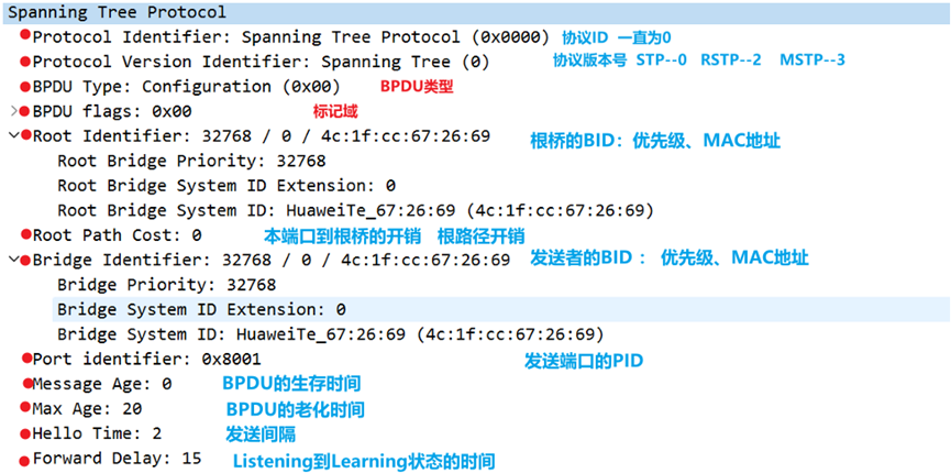
Message age : BPDU survival time, sent by the root bridge is 0, and it will increase every time it passes through a switch
Max age : BPDU aging time, the default is 20s, the maximum is 40s.
If Max age is less than 24s, Message age+1 for each switch
If Max age is 24~39s, Message age+2
If Max age is 40s, Mssage age+3.
When the Message age is equal to the Max age, the BPDU is considered invalid.
Hello timer : BPDU sending interval, the default is 2s
Forwarding delay : waiting delay, the default is 15s
BPDU type - 4 types
Configure BPDU periodic sending TCA=0 TC=0 in the tag field
The STP and RSTP type fields are somewhat different
STP----0X00 RSTP----0X02-RST BPDU MSTP----0X02-MST BPDU
Configure the function of BPDU
Election of root bridge and port roles
Configure the destination MAC address of the BPDU as multicast: 0180-c200-0000
STP configuration BPDU sending mode
Before the root bridge is elected, all devices will send configuration BPDUs, and only the root bridge will send configuration BPDUs after the election of the root bridge
Other non-root bridge devices will trigger and send configuration BPDUs after receiving configuration BPDUs sent by the root bridge, and will not actively send configuration BPDUs.
The designated port of the non-root bridge will only actively send the optimal BPDU when it receives the suboptimal configuration BPDU
RSRP configuration BPDU sending mode
Before the root bridge is elected, all devices will send configuration BPDUs
After the root bridge is elected and the topology is stable, no matter whether the non-root bridge receives the configuration BPDU from the root bridge or not, it will send the configuration BPDU according to the time specified by the Hello Timer.
STP's topology change confirmation BPDU is a configuration BPDU tag field TCA=1, TC=0 (TCA BPDU)
RSTP and MSTP also have this message for backward compatibility with STP
STP TCN BPDU sent after link failure
RSTP and MSTP also have this message for backward compatibility with STP
The type field is fixed at 0X80
Transferring topology change information in STP --- combined with TC and TCA bits in the BPDU marker field to achieve
Why STP Needs TCN BPDU Messages
In the switching network, the switch relies on the MAC address table to forward data. By default, the aging time of the MAC table entry is 300s. If the spanning tree topology changes, the forwarding path of the switch will also change. If the MAC address table does not age in time, it will cause An error occurred in data forwarding, so the MAC address entry needs to be updated in time
At this time, the aging time of MAC address entries can be shortened to 15s by sending TCN BPDU messages, so as to achieve the purpose of timely updating MAC address entries
Conditions for STP to send TCN BPDUs
At first, when any port enters the Forwarding state or enters the Disable state, it is considered that the topology has changed. Later, STP optimized the definition of topology changes.
- When the DP port enters the Forwarading state (it is recommended to set the DP port connected to the terminal device as an edge port for optimization)
- RP fails or RP enters Forwarding state
- When the DP of the root bridge fails, it directly sends TC BPDU (the failure of the DP port of the non-root bridge does not consider the topology to change)
STP's TCN BPDU working principle--how to achieve the purpose of updating the topology (through TCN, TC, TCA messages)
TC topology change message--clear the MAC address table learned from this interface----the specific method is not to clear directly, but to clear the MAC address table
The 300s aging time of the address table is changed to 15s
- After SWC perceives the change of network topology, it will send TCN BPDU message continuously
- After SWB receives the TCN message, it will set the TCA bit of BPDU Flags to 1, and then send it to SWC, telling SWC to stop sending TCN BPDU messages
- Then SWB forwards the TCN BPDU message sent by SWC to the root bridge
- SWA sets the TC bit of Flags in the BPDU message to 1 and then sends it (for 35s), notifying the downstream device to change the aging time of the MAC address entry to the Forward Delay time (15s).
Note: The root bridge does not need to reply to the TCA confirmation message

Topology change configuration BPDU is a configuration BPDU with TCA=1, TC=1 or TCA=0, TC=1 (TC BPDU) in the tag field
STP, RSTP, and MSTP all have this TC BPDU message
The topology change mechanism is optimized in RSTP/MSTP —only TC packets are used
Criteria for Judging Topology Changes Change
As long as a non-edge port migrates to the Forwarding state, the topology is considered to have changed
The working principle changes
When the network topology changes, the change point switch directly sends a BPDU message with TC set to the entire network, instead of notifying the root bridge first, and then the root bridge sends a TC message to the entire network
The change point switch starts a TC While Timer (2 times the Hello Time) for all non-edge designated ports of the switch device. During this time, clear the MAC addresses learned on all ports.
At the same time, the non-edge port sends RST BPDU to the outside, and the TC is set. Once the TC while Timer of the port times out, it stops sending RST BPDU
After receiving the RST BPDU with TC set, other switching devices clear the MAC addresses learned by all ports (except the port that received the RST BPDU), and then start TC While Timer for all non-edge designated ports and root ports. Repeat the above process

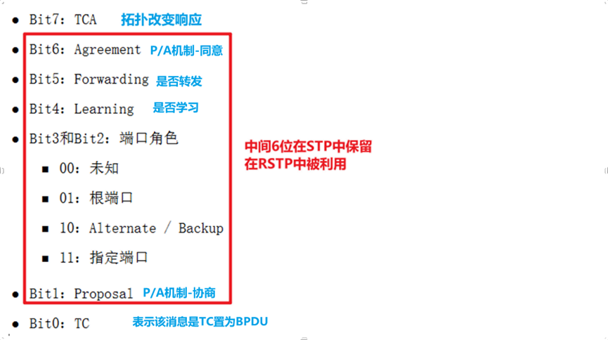
BPDU marker field
STP and RSTP are somewhat different