非同期通信ユニットは、通信時間間隔が2つの文字の間に固定されていないどのように文字を送信するが、文字間隔に隣接する2つのビット間に同時に固定されます。
キャラクタデバイスのパラレルデータにCPUのシリアル・データ・ストリームに供給される受け入れられながら、シリアルインタフェースは、連続したシリアルデータストリームに変換され、CPUから送信された並列データ文字を受信することができる装置です。

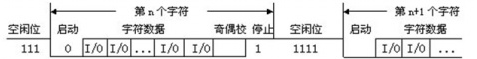
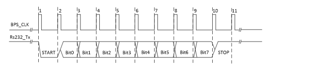
スタートビット:送信文字の開始を示す第1の論理「0」信号を発行します。
データビット:5~8論理「0」であってもよいし、「1」ASCIIコード(7)、拡張BCDコード(8)。小端送信
パリティビット:データビットとこれの後に、ビット数を作る「1」が偶数(偶数パリティ)または奇数(奇数パリティ)であるべきである
ストップビット:これは、文字データの終わりの兆候です。これは、1、1.5、2がハイレベルであってもよいです。
アイドル位置:論理「1」状態で、現在の行には、データ送信がないことを示します。
送信された
ことが9600を送信することが可能である、ビットを表すデータのシリアル通信のボーレートは、毎秒毎秒9600を送信することができるでは、
送信バイト
//-------1字节数据的发送-------
module uart_tx(
    input clk,
    input rst_n,
    input cnt_start,                                        //发送使能
	input [7:0]tx_data,
    output reg tx,
    output reg tx_done                                      //传输一个字节完成标志
    );

    reg [12:0]cnt_bps;
    parameter bps_t = 13'd5207;                             //传输1bit所需计数值
    always @(posedge clk or negedge rst_n)
    begin
       if(!rst_n)
          cnt_bps <= 13'd0;
       else if(cnt_bps == bps_t)
          cnt_bps <= 13'd0;
       else if(cnt_start)
          cnt_bps <= cnt_bps + 1'b1;
       else
          cnt_bps <= 1'b0;
    end
    wire bps_sig;
    assign bps_sig = (cnt_bps ==  13'd2604) ? 1'b1 : 1'b0;  //将采集数据的时刻放在波特率计数器每次循环计数的中间位置

    reg [3:0]state;
    always @(posedge clk or negedge rst_n)
    begin
       if(!rst_n) begin
          state <= 4'd0;
          tx <= 1'b1;
          tx_done <= 1'b0;
		  end
       else begin
          case(state)
			0: if(cnt_start & bps_sig) begin
				state <= state + 1'b1;
				tx <= 1'b0;
				end
			else begin
				state <= state;
				tx <= 1'b1;
				end
			1,2,3,4,5,6,7,8: if(bps_sig) begin
					tx <= tx_data[state - 1'b1]; //注意,从低位依次往高位发送
					state <= state + 1'b1;
					end
				else begin
					state <= state;
					tx <= tx;
					end
			9,10: if(bps_sig) begin
					state <= state + 1'b1;
					tx <= 1'b1;
					end
			11: begin
					state <= state + 1'b1;
					tx_done <= 1'b1;
				end
			12: begin
					state <= 1'b0;
					tx_done <= 1'b0;
				end
          endcase
		  end
    end
endmodule
データを受信
バイト転送の形で、:1-0-XXXXXXXX-0-1、すなわち、-1-0-検出立ち下がりエッジ(フラグスタート)受信バイトの開始後、レジスタに一つずつ受信、8ビットの受信機の端部は、単純なバイトを受信しています。
、必要とされる送受信ので、:とエンドマーカ(-0-1- 2ビット):1バイト= 8ビットが、しかし開始フラグ(-1-0- 2ビット)ので、ことが留意されますこの点を考慮。
//-------1字节的接收-------
module uart_rx(
    input clk,
    input rst_n,
	input data_rx,
    output [7:0] data_tx,
    output reg rx_int                                       //接收字节时状态为1
    );

    reg [12:0]cnt_bps;
	reg bps_start;
    parameter bps_t = 13'd5207;                             //传输1bit所需计数值
    always @(posedge clk or negedge rst_n)
    begin
       if(!rst_n)
          cnt_bps <= 13'd0;
       else if(cnt_bps == bps_t)
          cnt_bps <= 13'd0;
       else if(bps_start)
          cnt_bps <= cnt_bps + 1'b1;
       else
          cnt_bps <= 1'b0;
    end
    wire bps_sig;
    assign bps_sig = (cnt_bps ==  13'd2604) ? 1'b1 : 1'b0;  //将采集数据的时刻放在波特率计数器每次循环计数的中间位置

	reg	[1:0]	rx;
	always @(posedge	clk	or	negedge	rst_n)begin
		if(!rst_n)	rx <= 2'b11;
		else	begin
			rx[0]	<=	data_rx;
			rx[1]	<=	rx[0];
		end
	end
	wire nege_edge;
	assign nege_edge= rx[1]	& ~rx[0];						//检测下降沿

	reg	[3:0]num;
	always@(posedge	clk	or	negedge	rst_n)begin
		if(!rst_n)	begin
			bps_start <= 1'b0;
			rx_int <= 1'b0;
		end
		else	if(nege_edge)begin
			bps_start <= 1'b1;
			rx_int <= 1'b1;
		end
		else if(num == 4'd10)begin
			bps_start <= 1'b0;
			rx_int <= 1'b0;
		end
	end

	reg	[7:0]	rx_data_temp_r;								//当前数据接收寄存器
	reg	[7:0]	rx_data_r;									//用来锁存数据
	always@(posedge	clk	or	negedge	rst_n)begin
		if(!rst_n)	begin
			rx_data_r	<= 8'd0;
			rx_data_temp_r	<= 8'd0;
			num <= 4'd0;
			end
		else if(rx_int) begin
			if(bps_sig) begin
				num <= num + 1'b1;
				case(num)
					4'd1: rx_data_temp_r[0] <= data_rx;		//锁存第0bit
					4'd2: rx_data_temp_r[1] <= data_rx;		//锁存第1bit
					4'd3: rx_data_temp_r[2] <= data_rx;		//锁存第2bit
					4'd4: rx_data_temp_r[3] <= data_rx;		//锁存第3bit
					4'd5: rx_data_temp_r[4] <= data_rx;		//锁存第4bit
					4'd6: rx_data_temp_r[5] <= data_rx;		//锁存第5bit
					4'd7: rx_data_temp_r[6] <= data_rx;		//锁存第6bit
					4'd8: rx_data_temp_r[7] <= data_rx;		//锁存第7bit
					default: ;
				endcase
			end
			else if(num == 4'd10)begin
				rx_data_r <= rx_data_temp_r;
				num <= 4'd0;
			end
		end
	end

	assign	data_tx = rx_data_r;

endmodule
TB
module tb_uart_rx;

	// Inputs
	reg clk;
	reg rst_n;
	reg data_rx;

	// Outputs
	wire [7:0] data_tx;
	wire rx_int;

	// Instantiate the Unit Under Test (UUT)
	uart_rx uut (
		.clk(clk),
		.rst_n(rst_n),
		.data_rx(data_rx),
		.data_tx(data_tx),
		.rx_int(rx_int)
	);

	always #10 clk = ~clk;
	initial begin
		clk = 0;
		rst_n = 0;
		data_rx = 0;
		// Wait 20 ns for global reset to finish
		#20
		rst_n = 1;
		data_rx = 1;
		#104160
		rst_n = 1;
		data_rx = 0;	//起始位:-1-0-
		#104160			//传输11001011 (倒序)
		rst_n = 1;
		data_rx = 1;
		#104160
		rst_n = 1;
		data_rx = 1;
		#104160
		rst_n = 1;
		data_rx = 0;
		#104160
		rst_n = 1;
		data_rx = 1;
		#104160
		rst_n = 1;
		data_rx = 0;
		#104160
		rst_n = 1;
		data_rx = 0;
		#104160
		rst_n = 1;
		data_rx = 1;
		#104160
		rst_n = 1;
		data_rx = 1;
		#104160			//结束位 -0-1-
		rst_n = 1;
		data_rx = 0;
		#104160
		rst_n = 1;
		data_rx = 1;

		#104160			//复位
		rst_n = 0;
		data_rx = 0;
	end

endmodule
REF
https://blog.csdn.net/qq_40789587/article/details/84073419?depth_1-utm_source=distribute.pc_relevant.none-task-blog-BlogCommendFromMachineLearnPai2-5&utm_source=distribute.pc_relevant.none-task-blog-BlogCommendFromMachineLearnPai2-5
REF
https://blog.csdn.net/zjy900507/article/details/79789671
