AAPCS is the ARM architecture application binary (ABI) program calling interface released by arm. This document has multiple versions. The blogger’s first ARM program calling rules were in "ARM System and Structural Programming", but What is described in the book is ATPCS, and AAPCS is an upgraded version of ATPCS. Later, I went to the ARM official website and saw the AAPCS document, so I recorded it. There are multiple documents for ARM's ABI standard, of which this document is only one part. The link below contains relevant documents, you can take a look at them if you want to. Link to the latest version:GitHub - ARM-software/abi-aa: Application Binary Interface for the Arm® Architecture
1. Scope of application
AAPCS defines how subroutines are written, compiled, and individually assembled to work together. It describes the relationship between the calling routine and the called routine:
-
Calling a function requires creating a program state in which the called routine can begin execution.
-
The called function is obligated to preserve the program state of the calling function for the duration of the call.
-
The called function has the right to change the program state of the calling function.
This standard is the basis for a series of Procedure Call Standard (PCS) variants generated by choices that reflect the following alternative priorities:
-
code
-
performance
-
Functionality (e.g. ease of debugging, runtime checks, support for shared libraries)
Some aspects of each variant (such as R9 usage) are execution environment dependent, so:
-
It's possible for code that follows basic standards to be PCS-compatible with every variant.
-
It is unusual for code that conforms to one variant to be compatible with code that conforms to any other variant.
-
Code that conforms to a variant or base standard is not guaranteed to be compatible with execution environments that require those standards. The execution environment may impose further requirements beyond the scope of the procedure call standard.
The standard is divided into four parts:
-
The layout of the data.
-
Stack layout and calling patterns between functions with a common interface.
-
Variants are available with processor extensions, or when executing an environment-restricted addressing model.
-
C and C++ language bindings for common data types.
This specification does not standardize the representation of publicly visible non-C language entities (these are described in CPPABI32), and does not impose any requirements on the representation of language entities that are not visible on public interfaces.
2. Data type and alignment
2.1 Basic data types
The following table shows the machine's basic data types (machine types). A NULL pointer is always represented by all zeros.
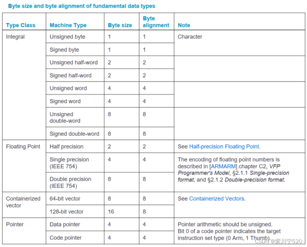
2.1.1 Half-precision floating point
An optional extension to the ARM architecture provides hardware support for half-precision values, currently supporting three formats:
-
Half-precision format of IEEE754-2008 standard
-
Alternative format for ARM, providing extra range, but no infinity (NaN)
-
The Brain floating point format provides a dynamic range similar to the 32-bit floating point format, but with less precision.
2.1.2 Containerized vectors
The contents of a containerized vector are opaque to most calling standards: the only defining aspects of its layout are the memory format (the way the basic types are stored in memory), and the mapping between different registers at call time.
2.2 Byte order
From a software perspective, memory is an array, and each byte has its own address.
The ABI supports two memory views implemented by the underlying hardware:
-
Big endian view (big endian mode)
-
Little endian view (little endian mode)
2.3 Composite types
A composite type is a collection of one or more basic data types that is processed as a single entity during a call. Can be any of the following:
-
Sequence, its members are arranged in memory in order (actually it is a C structure)
-
Federation, each member has the same address
-
array
The definition is recursive, that is, each type can contain composite types (structs within structs).
3 Basic procedure calling standards
This part defines a machine-level, core-register-only call standard instruction set common to ARM and Thumb. It should be used on systems without floating point hardware, or when a high degree of interoperability with Thumb code is required.
3.1 Machine registers
The ARM architecture defines a core instruction set, as well as additional instructions for coprocessors. The core instruction set can access core registers, and the coprocessor can provide registers for additional operations.
3.1.1 Core registers
The ARM and Thumb instruction sets have 16 32-bit registers, R0--R15, and a status register (CPSR). The following table shows the functions of each register.
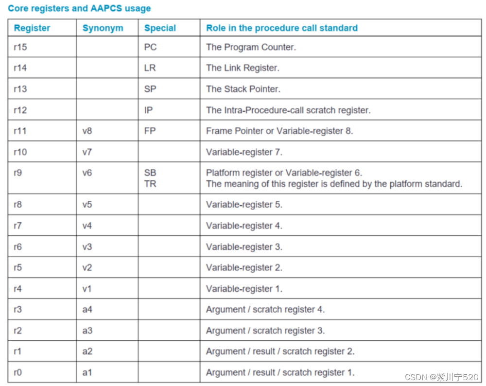
The first four registers r0-r3 (a1-a4) are used to pass parameter values to subroutines and return result values from functions. They can also be used to save intermediate values inside routines (but usually only between subroutine calls).
Register r12 (IP) may be used by the linker as a temporary register between the routine and any subroutines called (see Linker Use of IP for details). It can also be used inside a routine to save intermediate values between subroutine calls.
In some variants, register r11 (FP) may be used as a frame pointer to link the frame activation records into a linked list.
The role of register r9 depends on the platform. The virtual platform can assign any role to this register and must document this usage. For example, it can be specified as a static base address (SB) in a position-free data model, or as a thread register (TR) in an environment with thread-local storage. Use of this register may be required to keep its value persistent between all calls. Virtual platforms that have no need for this special register can specify r9 as an additional callee-saved variable register v6.
Usually, registers r4-r8, r10 and r11 (v1-v5, v7 and v8) are used to hold the values of local variables of the routine. Among them, only v1-v4 can be used uniformly by the entire Thumb instruction set, but AAPCS does not require Thumb code to use only these registers.
The subroutine must preserve the contents of registers r4-r8, r10, r11, and SP (in the PCS variant, r9 is also preserved when r9 is specified as v6).
In all variants of the procedure calling standard, registers r12-r15 have a special role. Among these roles, they are labeled IP, SP, LR and PC.
CPSR is a global register with the following properties:
-
When entering or returning from the public interface, the N, Z, C, V and Q bits (bits 27-31) and the GE[3:0] bits (bits 16-19) are undefined. The Q and GE[3:0] bits may be modified only when executing on a processor that supports these features.
-
On Arm architecture 6, the E bit (bit 8) can be used to temporarily change the endianness of data accesses to memory in applications executing little-endian mode, or in big-endian-8 mode. The application must have the specified endianness, and the setting of the E bit must match the application's specified endianness when entering and exiting any public interface.
-
The T bit (bit 5) and the J bit (bit 24) are execution status bits. Only instructions specifically designed to modify these bits can change them.
-
The A, I, F, and M[4:0] bits (bits 0-7) are privileged bits and can only be modified by applications designed to run explicitly in privileged mode.
-
All other bits are reserved and must not be modified. It is undefined whether these bits read as zero or one, or whether they remain unchanged across public interfaces.
3.1.1.1 Handling values larger than 32 bits
Basic types larger than 32 bits can be passed as arguments to function calls or returned as the result of function calls. When these types are in core registers, the following rules apply:
-
Dword-sized types are passed in two consecutive registers (for example, r0 and r1, or r2 and r3). The contents of the register are as if the value were loaded from the memory representation using a single LDM instruction.
-
A 128-bit containerized vector is passed in four consecutive registers. The contents of the register are as if the value was loaded from memory using a single LDM instruction.
3.2 Process, memory and stack
AAPCS applies to a single execution thread or process (hereinafter collectively referred to as a process). A process has a program state defined by the underlying machine registers and the contents of memory it can access. The amount of memory a process is able to access without causing runtime failures may change during process execution. A process's memory generally falls into five categories:
-
The code (the program being executed) must be readable by the process, but does not have to be writable by it.
-
Read only static data.
-
Writable static data.
-
heap.
-
stack.
Writable static data can be further divided into initialized, zero-initialized and uninitialized data. With the exception of the stack, there is no requirement that each memory class occupy a single contiguous region of memory. A process must always have some code and a stack, but does not have to have any other memory categories.
The heap is an area of memory managed by the process itself (for example, using C's malloc function). Typically used to create dynamic data objects.
A conforming program must execute only instructions in a region of memory designated as containing code.
3.2.1 Stack
The stack is a contiguous area of memory that can be used to store local variables and pass additional parameters to subroutines when the parameter register is insufficient.
The stack implementation is completely descending, and the current stack range is saved in register SP (r13). The stack usually has a base address and a limit address, although in practice the application may not be able to determine the exact numerical value of either value.
The stack may have a fixed size or may be dynamically expandable (by adjusting the stack limit downwards).
The rules for maintaining a stack are divided into two parts: a set of constraints that must be adhered to at all times and an additional constraint that must be adhered to in the public interface.
3.2.1.1 General stack constraints
The following basic constraints always need to be met:
-
Stack limit ≤ SP ≤ stack base address. The stack pointer must be within the scope of the stack.
-
SP mod 4 = 0. The stack must always be aligned to word boundaries.
-
A process can only store data within a closed range of the entire stack, bounded by [SP, stack base address - 1] (where SP is the value of register r13).
3.2.1.2 Stack constraints of public interfaces
At the public interface, the stack must also comply with the following constraints: SP mod 8 = 0. The stack must be doubleword aligned.
3.2.1.3 Stack probing
To ensure stack integrity, a process may issue a stack probe immediately before allocating additional stack space (moving from SP_old to SP_new). The stack probe must be in the area [SP_new, SP_old - 1] and can be a read or write operation. The minimum interval for stack probing is defined by the target platform, but must be at least 4K bytes. No recoverable data can be saved below the currently allocated stack area.
3.2.1.4 Frame pointer
The platform may require the construction of a list of stack frames that describes the current call hierarchy in the program. Each frame should be linked to its caller's frame via a frame record using two 32-bit values on the stack. The frame record of the innermost frame (belonging to the most recent routine call) should be pointed to by the Frame Pointer register (FP). The lowest-addressed word should point to the previous frame record, and the highest-addressed word should contain the value passed to LR when entering the current function. The end of the frame record chain is indicated by the address of the previous frame being zero. The frame record position in the stack frame is unspecified. The frame pointer register cannot be updated until the new frame record is completely constructed.
3.3 Subroutine call
Both the Arm and Thumb instruction sets contain a basic subroutine call instruction BL to perform branch and link operations. The effect of executing BL is to transfer the next sequential value of the program counter, the return address, to the link register (LR) and the target address to the program counter (PC). Bit 0 of the link register will be set to 1 if the BL instruction is executed from Thumb state, or to 0 if executed from Arm state. The result is a transfer of control to the target address, passing the return address in LR as an additional argument to the called subroutine.
When the return address is loaded back into the PC (see Interaction), control will return to the instruction following the BL.
3.4 Return results
The way a function returns a result depends on the type of the result. For basic standards:
-
Half-precision floating point types return the least significant 16 bits in r0.
-
Primitive data types smaller than 4 bytes are zero-extended or sign-extended to a word and returned in r0.
-
Word-sized primitive data types (e.g., int, float) are returned in r0.
-
Dword-sized primitive data types (for example, longlong, double, and 64-bit containerized vectors) are returned in r0 and r1.
-
128-bit containerized vectors are returned in r0-r3.
-
Composite types no larger than 4 bytes are returned in r0. The format is like storing the result at a word aligned address in memory and then loading it into r0 using the LDR instruction. Any bits in r0 that are outside the range of the result have an unspecified value.
-
Composite types larger than 4 bytes, or whose size cannot be statically determined by the caller and callee, will be stored in memory with their address as an extra parameter passed when calling the function (Parameter Passing, Basic PCS, Rule A.4 ). The memory used by the result can be modified at any time during the function call.
3.5 Parameter passing
The base standard provides mechanisms for passing parameters in core registers (r0-r3) and on the stack. For subroutines that require a small number of parameters, only registers are used, greatly reducing the cost of calling them. Parameter passing is defined as a two-level conceptual model:
-
Mapping from source language parameters to machine types.
-
Arrange the machine type to produce the final parameter list.
The mapping from source languages to machine types is specific to each language and described in separate documents (C and C++ language bindings are described in Arm C and C++ Language Maps). The result is an ordered list of arguments to be passed to the subroutine.
In the following description, it is assumed that there are many coprocessors available for passing and receiving parameters. Coprocessor registers are divided into different categories. An argument can be a candidate for at most one coprocessor register class. Parameters suitable for allocation to a coprocessor register are called coprocessor register candidates (CPRC). In the base standard, there are no parameters suitable for the coprocessor register class.
A variadic function is always organized in a basic standard way.
For the caller, it is assumed that sufficient stack space has been allocated to accommodate the stacked parameters before orchestration: in fact, the amount of stack space required is not known until parameter orchestration is completed. The callee can modify any stack space used to receive parameter values from the caller.
When a composite type parameter is assigned (fully or partially) to a core register, it behaves as if the parameter had been stored to a word-aligned (4-byte) address in memory and then loaded into contiguous registers using the appropriate load multi-register instruction .
4. Summary
This article is of a note-taking nature. In the article, the blogger only selected a part of the records. However, the English is not very good, and the level of understanding and translation is probably not enough. Interested students can read the original version. The blogger uploads it to his code cloud warehouse, code cloud link: https://gitee.com/zichuanning520/htq_library
Link to the latest version:GitHub - ARM-software/abi-aa: Application Binary Interface for the Arm® Architecture