Author information: Miao Hao 15515026488 WeChat account
This article is excerpted from "Huawei ICT Competition-Network Track Learning Space (China)". If there is any infringement, please contact the author in time to delete the article.
1. Project background
The competition simulated a scenario in which the enterprise network of a large company connected to the data center through the WAN.
Considering the needs of network redundancy and traffic load balancing, the enterprise network deploys MSTP and firewall dual-machine hot backup to carry web services and Internet access services. At the same time, in order to meet the wireless office needs of employees, engineers need to deploy WLAN equipment in the corporate network to access the Internet.
In the context of using abundant network resources to build enterprise networks and data center networks, engineers have proven that they face serious security issues. NGFW can be deployed at the exit of enterprise networks and data center networks to help reduce security risks and help achieve security and Efficient network management.
The company's private cloud is deployed in the data center room of the headquarters, and various business systems of the company are deployed on its private cloud. The web server where the company's OA system is located is deployed in the data center of the headquarters. Each branch of the company needs to access it through MPLS VPN. The Web-Server in the remote data center, and for security reasons, the private network address of the Web-Server is not advertised to the WAN, but is accessed through an external public network address 100.1.1.1, the traffic from Web-Client to Web-Server It is necessary to perform destination address conversion on the firewall FW3 and convert it into the Web-Server private address to achieve access.
In order to realize the intercommunication of business virtual machines of data center tenants located in different subnets, here the business virtual machines are VM1 and VM2. A GRE tunnel needs to be deployed in the data center to open the Layer 3 channels of VM1 and VM2.
The WAN provides a link between the enterprise's intranet and the remote headquarters data center, and provides the deployment of MPLS VPN on the WAN to implement the enterprise's Internet dedicated line function to ensure the effect of business isolation on the WAN.
2. Network track

The experimental environment uses the following equipment:
- 2 sets of S5700 (SW2, SW3)
- 1 S3700 (SW1)
- 3 firewalls USG6000V (FW1-FW3)
- 7 routers (PE1, PE2, P, Internet, Leaf1, Leaf2)
- 1 AC6605 (AC)
- 1 AP6050 (AP)
- 1 WLAN terminal (PC)
- 1 Web server (Web-Server)
- 1 Web client (Web-Client)
- 2 virtual machines (VM1, VM2)

 2.1 Competition tasks
Task 1: VLAN
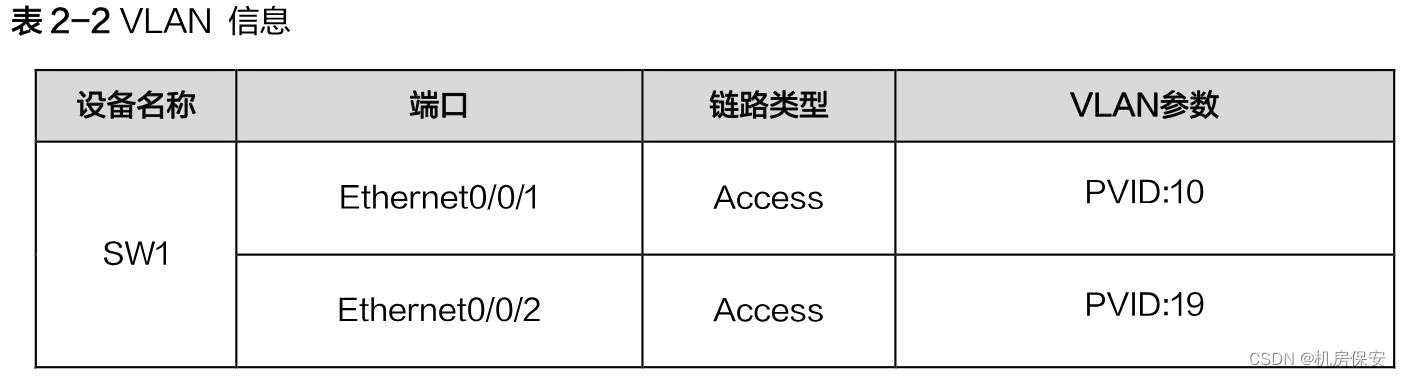
According to the 2-2 plan, configure the network device name, configure the VLAN link type and VLAN parameters on SW1, SW2, and SW3, and configure the sub-interface and sub-interface ID on PE1, FW1, and FW2.


Task 2: IP address
Configure the network device name and interface IP address according to Figure 2-1 and Table 2-3.


Configuration process:
任务1/2:设备命名/VLAN/IP地址
#SW1
<Huawei>system-view
[Huawei]sysname SW1
[SW1]vlan batch 2 to 20
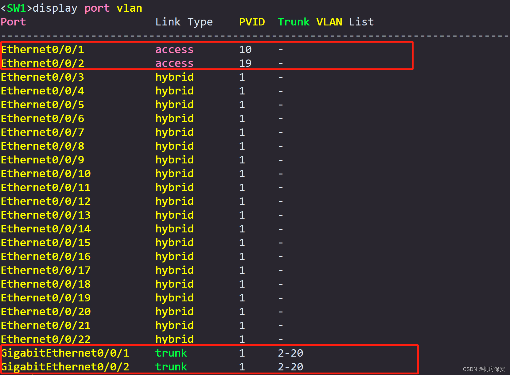
[SW1]interface Ethernet0/0/1
[SW1-Ethernet0/0/1]port link-type access
[SW1-Ethernet0/0/1]port default vlan 10
[SW1]interface Ethernet0/0/2
[SW1-Ethernet0/0/2]port link-type access
[SW1-Ethernet0/0/2]port default vlan 19
[SW1]port-group group-member GigabitEthernet 0/0/1 GigabitEthernet 0/0/2
[SW1-port-group]port link-type trunk
[SW1-port-group]undo port trunk allow-pass vlan 1
[SW1-port-group]port trunk allow-pass vlan 2 to 20
#SW2
<Huawei>system-view
[Huawei]sysname SW2
[SW2]vlan batch 2 to 20
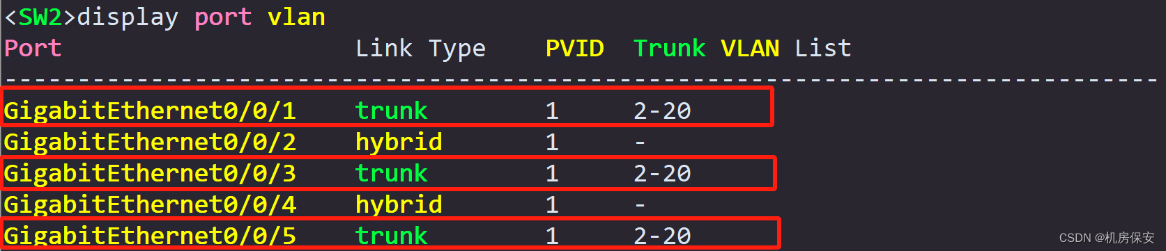
[SW2]port-group group-member GigabitEthernet 0/0/1 GigabitEthernet 0/0/3 GigabitEthernet 0/0/5
[SW2-port-group]port link-type trunk
[SW2-port-group]undo port trunk allow-pass vlan 1
[SW2-port-group]port trunk allow-pass vlan 2 to 20
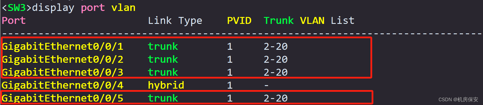
#SW3
<Huawei>system-view
[Huawei]sysname SW3
[SW3]vlan batch 2 to 20
[SW3]port-group group-member GigabitEthernet 0/0/1 to GigabitEthernet 0/0/3 GigabitEthernet 0/0/5
[SW3-port-group]port link-type trunk
[SW3-port-group]undo port trunk allow-pass vlan 1
[SW3-port-group]port trunk allow-pass vlan 2 to 20
#FW1
<USG6000V1>system-view
[USG6000V1]sysname FW1
[FW1]interface GigabitEthernet 1/0/5.1
[FW1-GigabitEthernet1/0/5.1]vlan-type dot1q 10
[FW1-GigabitEthernet1/0/5.1]ip address 192.168.1.2 24
[FW1]interface GigabitEthernet 1/0/5.2
[FW1-GigabitEthernet1/0/5.2]vlan-type dot1q 20
[FW1-GigabitEthernet1/0/5.2]ip address 192.168.2.2 24
[FW1]interface GigabitEthernet 1/0/3.1
[FW1-GigabitEthernet1/0/3.1]vlan-type dot1q 1
[FW1-GigabitEthernet1/0/3.1]ip address 10.2.2.1 30
[FW1]interface GigabitEthernet 1/0/1
[FW1-GigabitEthernet1/0/1]ip address 15.1.1.1 24
[FW1]interface GigabitEthernet 1/0/3
[FW1-GigabitEthernet1/0/3]ip address 10.2.1.1 30
#FW2
<USG6000V1>system-view
[USG6000V1]sysname FW2
[FW2]interface GigabitEthernet 1/0/5.1
[FW2-GigabitEthernet1/0/5.1]vlan-type dot1q 10
[FW2-GigabitEthernet1/0/5.1]ip address 192.168.1.3 24
[FW2]interface GigabitEthernet 1/0/5.2
[FW2-GigabitEthernet1/0/5.2]vlan-type dot1q 20
[FW2-GigabitEthernet1/0/5.2]ip address 192.168.2.3 24
[FW2]interface GigabitEthernet 1/0/3.1
[FW2-GigabitEthernet1/0/3.1]vlan-type dot1q 1
[FW2-GigabitEthernet1/0/3.1]ip address 10.3.2.1 30
[FW2]interface GigabitEthernet 1/0/1
[FW2-GigabitEthernet1/0/1]ip address 15.1.1.2 24
[FW2]interface GigabitEthernet 1/0/3
[FW2-GigabitEthernet1/0/3]ip address 10.3.1.1 30
#PE1
<Huawei>system-view
[Huawei]sysname PE1
[PE1]interface GigabitEthernet 0/0/1.1
[PE1-GigabitEthernet0/0/1.1]dot1q termination vid 1
[PE1-GigabitEthernet0/0/1.1]arp broadcast enable
[PE1-GigabitEthernet0/0/1.1]ip address 10.2.2.2 30
[PE1]interface GigabitEthernet 0/0/3.1
[PE1-GigabitEthernet0/0/3.1]dot1q termination vid 1
[PE1-GigabitEthernet0/0/3.1]arp broadcast enable
[PE1-GigabitEthernet0/0/3.1]ip address 10.3.2.2 30
[PE1]interface LoopBack 0
[PE1-LoopBack0]ip address 1.1.1.1 32
[PE1]interface GigabitEthernet0/0/1
[PE1-GigabitEthernet0/0/1]ip address 10.2.1.2 30
[PE1]interface GigabitEthernet0/0/2
[PE1-GigabitEthernet0/0/2]ip address 20.1.1.1 30
[PE1]interface GigabitEthernet0/0/3
[PE1-GigabitEthernet0/0/3]ip address 10.3.1.2 30
#AC1
<AC6605>system-view
[AC6605]sysname AC
[AC]vlan batch 19 20
[AC]interface GigabitEthernet 0/0/1
[AC-GigabitEthernet0/0/1]port link-type trunk
[AC-GigabitEthernet0/0/1]undo port trunk allow-pass vlan 1
[AC-GigabitEthernet0/0/1]port trunk allow-pass vlan 19 20
#FW3
<USG6000V1>system-view
[USG6000V1]sysname FW3
[FW3]interface GigabitEthernet 1/0/1
[FW3-GigabitEthernet1/0/1]ip address 30.1.1.1 30
[FW3]interface GigabitEthernet 1/0/2
[FW3-GigabitEthernet1/0/2]ip address 20.1.3.2 30
#P
<Huawei>system-view
[Huawei]sysname P
[P]interface LoopBack 0
[P-LoopBack0]ip address 2.2.2.2 32
[P]interface GigabitEthernet0/0/1
[P-GigabitEthernet0/0/1]ip address 20.1.2.1 30
[P]interface GigabitEthernet0/0/2
[P-GigabitEthernet0/0/2]ip address 20.1.1.2 30
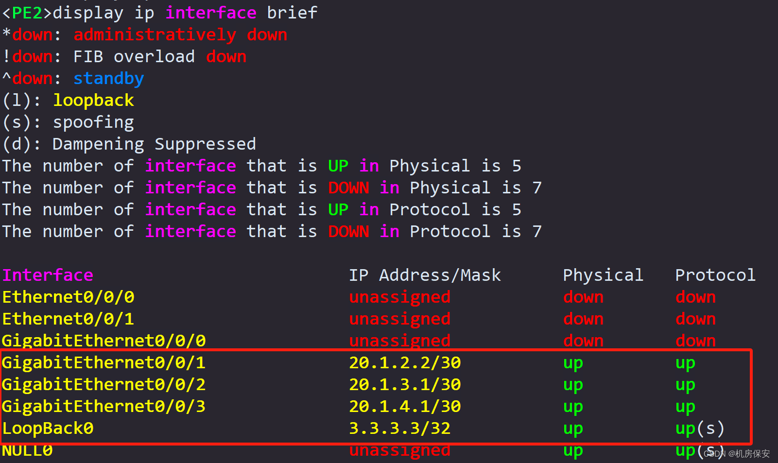
#PE2
<Huawei>system-view
[Huawei]sysname PE2
[PE2]interface LoopBack 0
[PE2-LoopBack0]ip address 3.3.3.3 32
[PE2]interface GigabitEthernet0/0/1
[PE2-GigabitEthernet0/0/1]ip address 20.1.2.2 30
[PE2]interface GigabitEthernet0/0/2
[PE2-GigabitEthernet0/0/2]ip address 20.1.3.1 30
[PE2]interface GigabitEthernet0/0/3
[PE2-GigabitEthernet0/0/3]ip address 20.1.4.1 30
#Internet
<Huawei>system-view
[Huawei]sysname Internet
[Internet]interface LoopBack 0
[Internet-LoopBack0]ip address 16.16.16.16 32
[Internet]interface GigabitEthernet0/0/3
[Internet-GigabitEthernet0/0/3]ip address 20.1.4.2 30
#DC-GW
<Huawei>system-view
[Huawei]sysname DC-GW
[DC-GW]interface LoopBack 0
[DC-GW-LoopBack0]ip address 11.11.11.11 32
[DC-GW]interface GigabitEthernet0/0/1
[DC-GW-GigabitEthernet0/0/1]ip address 30.1.1.2 30
[DC-GW]interface GigabitEthernet0/0/2
[DC-GW-GigabitEthernet0/0/2]ip address 30.1.2.1 30
[DC-GW]interface GigabitEthernet0/0/3
[DC-GW-GigabitEthernet0/0/3]ip address 30.1.3.1 30
#Leaf1
<Huawei>system-view
[Huawei]sysname Leaf1
[Leaf1]interface LoopBack 0
[Leaf1-LoopBack0]ip address 12.12.12.12 32
[Leaf1]interface GigabitEthernet0/0/1
[Leaf1-GigabitEthernet0/0/1]ip address 172.16.3.254 24
[Leaf1]interface GigabitEthernet0/0/2
[Leaf1-GigabitEthernet0/0/2]ip address 30.1.2.2 30
[Leaf1]interface GigabitEthernet0/0/3
[Leaf1-GigabitEthernet0/0/3]ip address 172.16.1.254 24
#Leaf2
<Huawei>system-view
[Huawei]sysname Leaf2
[Leaf2]interface LoopBack 0
[Leaf2-LoopBack0]ip address 13.13.13.13 32
[Leaf2]interface GigabitEthernet0/0/1
[Leaf2-GigabitEthernet0/0/1]ip address 172.16.2.254 24
[Leaf2]interface GigabitEthernet0/0/3
[Leaf2-GigabitEthernet0/0/3]ip address 30.1.3.2 30verify:


Task 3: MSTP configuration
In order to achieve the loop prevention function and traffic load balancing of the Layer 2 network, the MSTP function needs to be configured on SW1, SW2, and SW3.
- Configure the region name as RG1.
- Map VLAN2 to VLAN10 to spanning tree instance instance 1, and map VLAN11 to VLAN20 to spanning tree instance instance 2.
- Configure SW2 as the root bridge of instance 1 and the backup root bridge of instance 2; configure SW3 as the root bridge of instance 2 and the backup root bridge of instance 1.
- Configure SW2's GE 0/0/1 port as STP root protection and disable the STP function of GE0/0/5; configure SW3's GE0/0/2 port as STP root protection and configure GE0/0/1 as an STP edge port. , turn off the STP function of GE0/0/5 port.
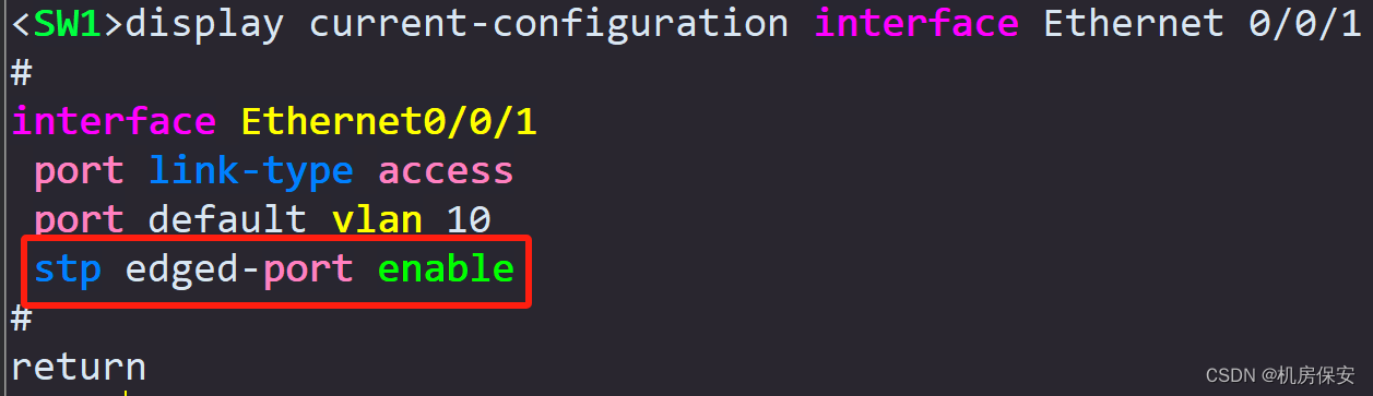
- Configure E0/0/1 and E0/0/2 of SW1 as STP edge ports.
Configuration process:
任务3:MSTP
#SW2
[SW2]stp region-configuration
[SW2-mst-region]region-name RG1
[SW2-mst-region]instance 1 vlan 2 to 10
[SW2-mst-region]instance 2 vlan 11 to 20
[SW2-mst-region]active region-configuration
[SW2]stp instance 1 root primary
[SW2]stp instance 2 root secondary
[SW2]interface GigabitEthernet 0/0/1
[SW2-GigabitEthernet0/0/1]stp root-protection
[SW2]interface GigabitEthernet 0/0/5
[SW2-GigabitEthernet0/0/5]stp disable

#SW3
[SW3]stp region-configuration
[SW3-mst-region]region-name RG1
[SW3-mst-region]instance 1 vlan 2 to 10
[SW3-mst-region]instance 2 vlan 11 to 20
[SW3-mst-region]active region-configuration
[SW3]stp instance 1 root secondary
[SW3]stp instance 2 root primary
[SW3]interface GigabitEthernet 0/0/2
[SW3-GigabitEthernet0/0/2]stp root-protection
[SW3]interface GigabitEthernet 0/0/1
[SW3-GigabitEthernet0/0/1]stp edged-port enable
[SW3]interface GigabitEthernet 0/0/5
[SW3-GigabitEthernet0/0/5]stp disable

#SW1
[SW1]stp region-configuration
[SW1-mst-region]region-name RG1
[SW1-mst-region]instance 1 vlan 2 to 10
[SW1-mst-region]instance 2 vlan 11 to 20
[SW1-mst-region]active region-configuration
[SW1]port-group group-member Ethernet 0/0/1 Ethernet 0/0/2
[SW1-port-group]stp edged-port enable
verify:


Task 4: Firewall security zone configuration
In order to meet network security requirements, it is necessary to deploy firewalls, plan security areas as required, and release necessary port permissions in accordance with the principle of least privilege to ensure normal business communication.
Please complete the security zone configuration of the firewall according to the data plan in Table 2-4 below.


verify:


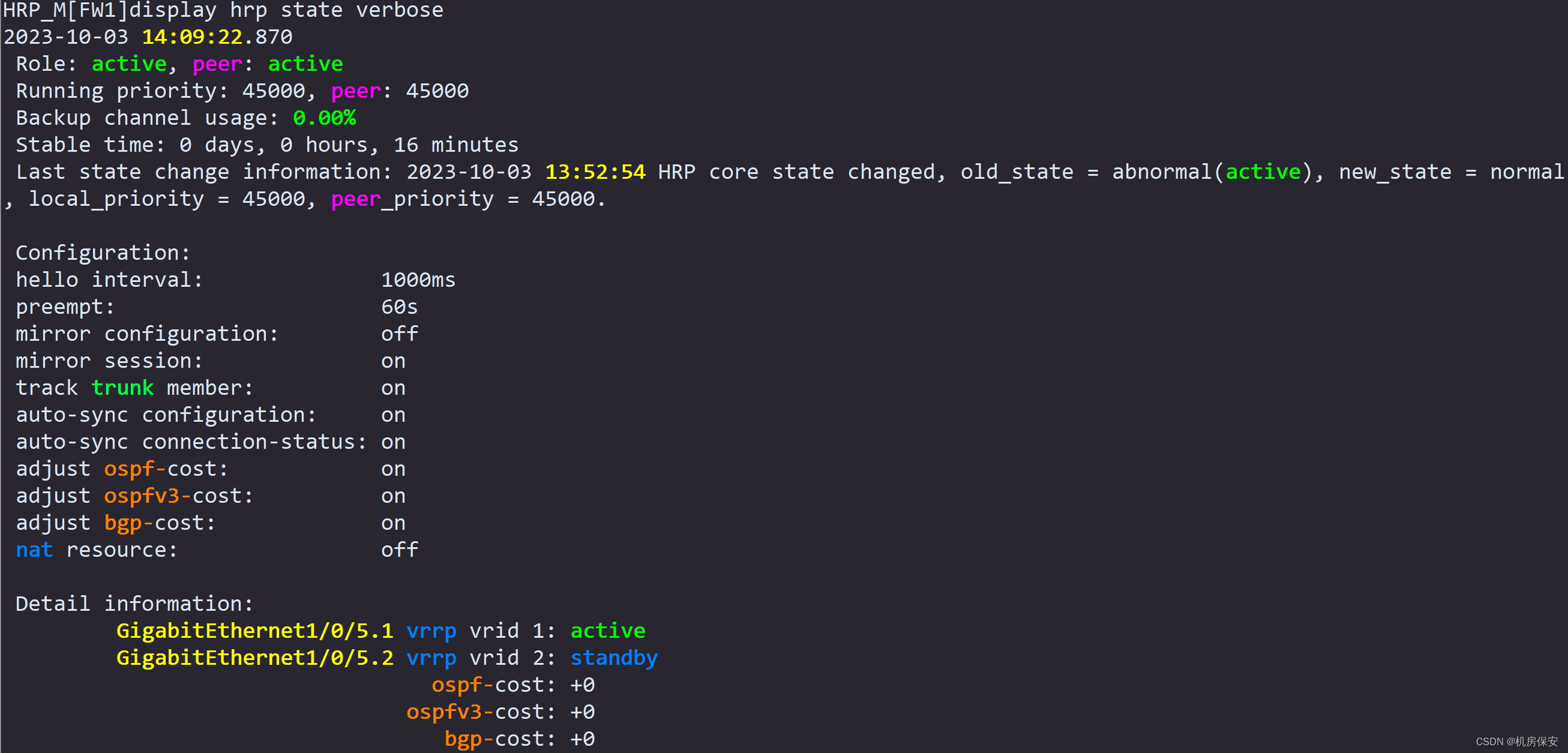
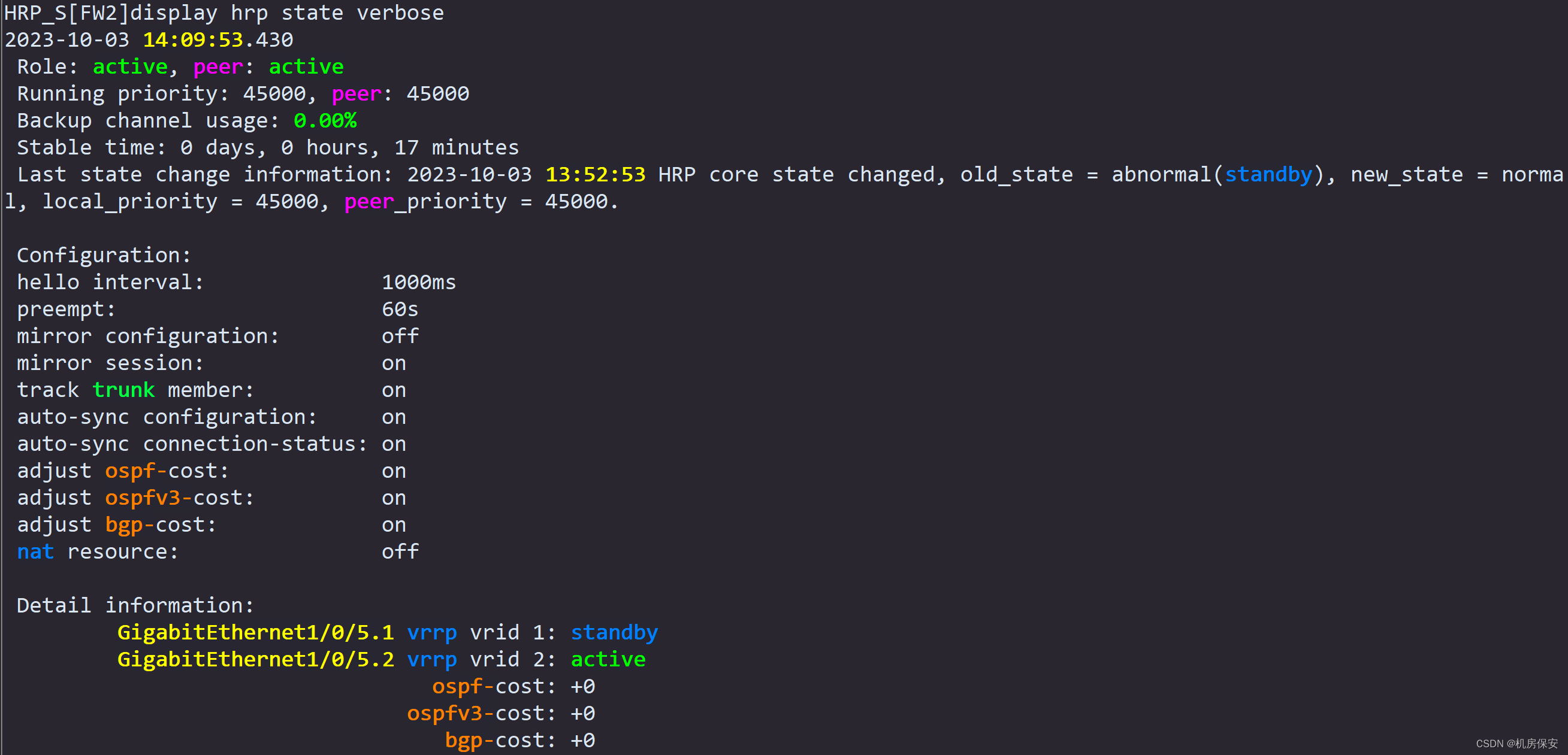
Task 5: Firewall VRRP, dual-machine hot backup and security policy configuration
In order to avoid single points of failure of the firewall and make full use of network resources, the load balancing mode is used to deploy firewall dual-machine hot backup to increase network robustness.
- Complete the VRRP configuration according to the VRRP planning in Table 2-5.
- Enable the hrp function of FW1 and FW2, configure the G1/0/1 interface of FW1 and FW2 as the HRP interface, and enable the session fast backup function.
- Then complete the firewall security policy configuration as required.
- FW1: Create a security policy named "web" to allow web service traffic;
- FW1: Create a security policy named "Wireless" to allow WLAN traffic;
- FW3: Create a security policy named "web" to allow web service traffic;
- Configure the NAT server function on FW3. The global address and port number are 100.1.1.1 and 8080 respectively, and the inside address and protocol are 172.16.1.1 and http respectively.
The security policy prohibits full access and requires all security policies to be configured in detail according to actual conditions.
Configuration process:
任务4:防火墙安全区域配置
#FW1
[FW1]firewall zone trust
[FW1-zone-trust]add interface GigabitEthernet 1/0/5.1
[FW1-zone-trust]add interface GigabitEthernet 1/0/5.2
[FW1]firewall zone untrust
[FW1-zone-untrust]add interface GigabitEthernet 1/0/3
[FW1-zone-untrust]add interface GigabitEthernet 1/0/3.1
[FW1]firewall zone dmz
[FW1-zone-dmz]add interface GigabitEthernet 1/0/1

#FW2
[FW2]firewall zone trust
[FW2-zone-trust]add interface GigabitEthernet 1/0/5.1
[FW2-zone-trust]add interface GigabitEthernet 1/0/5.2
[FW2]firewall zone untrust
[FW2-zone-untrust]add interface GigabitEthernet 1/0/3
[FW2-zone-untrust]add interface GigabitEthernet 1/0/3.1
[FW2]firewall zone dmz
[FW2-zone-dmz]add interface GigabitEthernet 1/0/1

#FW3
[FW3]firewall zone trust
[FW3-zone-trust]add interface GigabitEthernet 1/0/1
[FW3]firewall zone untrust
[FW3-zone-untrust]add interface GigabitEthernet 1/0/2

任务5:防火墙VRRP、双机热备和安全策略配置
防火墙VRRP
#FW1
[FW1]interface GigabitEthernet 1/0/5.1
[FW1-GigabitEthernet1/0/5.1]vrrp vrid 1 virtual-ip 192.168.1.254 active
[FW1]interface GigabitEthernet 1/0/5.2
[FW1-GigabitEthernet1/0/5.2]vrrp vrid 2 virtual-ip 192.168.2.254 standby

#FW2
[FW2]interface GigabitEthernet 1/0/5.1
[FW2-GigabitEthernet1/0/5.1]vrrp vrid 1 virtual-ip 192.168.1.254 standby
[FW2]interface GigabitEthernet 1/0/5.2
[FW2-GigabitEthernet1/0/5.2]vrrp vrid 2 virtual-ip 192.168.2.254 active

HRP
#FW1
[FW1]hrp interface GigabitEthernet 1/0/1 remote 15.1.1.2
[FW1]hrp enable
HRP_M[FW1]hrp mirror session enable
HRP_M[FW1]hrp auto-sync config static-route  (+B)

#FW2
[FW2]hrp interface GigabitEthernet 1/0/1 remote 15.1.1.1
[FW2]hrp enable
HRP_S[FW2]hrp mirror session enable

安全策略
#FW1
HRP_M[FW1]security-policy  (+B)
HRP_M[FW1-policy-security]rule name web (+B)
HRP_M[FW1-policy-security-rule-web]source-zone trust  (+B)
HRP_M[FW1-policy-security-rule-web]destination-zone untrust  (+B)
HRP_M[FW1-policy-security-rule-web]source-address 192.168.1.1 32 (+B)
HRP_M[FW1-policy-security-rule-web]destination-address 172.16.1.1 32 (+B)
HRP_M[FW1-policy-security-rule-web]service http (+B)
HRP_M[FW1-policy-security-rule-web]service https  (+B)
HRP_M[FW1-policy-security-rule-web]action permit  (+B)
HRP_M[FW1-policy-security]rule name Wireless (+B)
HRP_M[FW1-policy-security-rule-Wireless]source-zone trust  (+B)
HRP_M[FW1-policy-security-rule-Wireless]source-zone local  (+B)
HRP_M[FW1-policy-security-rule-Wireless]source-zone untrust  (+B)
HRP_M[FW1-policy-security-rule-Wireless]destination-zone untrust  (+B)
HRP_M[FW1-policy-security-rule-Wireless]destination-zone trust  (+B)
HRP_M[FW1-policy-security-rule-Wireless]destination-zone local  (+B)
HRP_M[FW1-policy-security-rule-Wireless]source-address 192.168.2.0 24 (+B)
HRP_M[FW1-policy-security-rule-Wireless]action permit  (+B)
HRP_M[FW1]int g1/0/5.1 (+B)
HRP_M[FW1-GigabitEthernet1/0/5.1]service-manage ping permit  (+B)
HRP_M[FW1]int g1/0/5.2 (+B)
HRP_M[FW1-GigabitEthernet1/0/5.2]service-manage ping permit  (+B)

#FW3
[FW3]security-policy
[FW3-policy-security]rule name web
[FW3-policy-security-rule-web]source-zone untrust
[FW3-policy-security-rule-web]destination-zone trust
[FW3-policy-security-rule-web]source-address 192.168.1.1 32
[FW3-policy-security-rule-web]destination-address 172.16.1.1 32
[FW3-policy-security-rule-web]service http
[FW3-policy-security-rule-web]service https
[FW3-policy-security-rule-web]action permit
[FW3-policy-security]rule name BGP
[FW3-policy-security-rule-BGP]source-zone untrust
[FW3-policy-security-rule-BGP]destination-zone local
[FW3-policy-security-rule-BGP]source-address 20.1.3.1 mask 255.255.255.255
[FW3-policy-security-rule-BGP]destination-address 20.1.3.2 mask 255.255.255.255
[FW3-policy-security-rule-BGP]service bgp
[FW3-policy-security-rule-BGP]service tcp
[FW3-policy-security-rule-BGP]action permit
[FW3]security-policy
[FW3-policy-security]rule name OSPF
[FW3-policy-security-rule-OSPF]source-zone trust
[FW3-policy-security-rule-OSPF]destination-zone local
[FW3-policy-security-rule-OSPF]source-address 30.1.1.2
[FW3-policy-security-rule-OSPF]service ospf
[FW3-policy-security-rule-OSPF]action permit

NAT Server
#FW3
[FW3]nat server nat_server zone untrust protocol tcp global 100.1.1.1 8080 inside 172.16.1.1 www
verify:


Task 6: Public network static routing configuration (refer to Figure 2-2, Figure 2-3 and description for routing)
- In order to divert traffic to the Internet and traffic to the data center Web-server to the WAN, static routes need to be configured on FW1 and FW2. The main interface of PE1 is used to receive Internet traffic, and the sub-interface of PE1 is used to receive Web-Server traffic. Configure two return static routes on PE1 that point to WLAN clients. The return routes need to point to FW1 and FW2 for load balancing and are used to guide Internet return traffic.
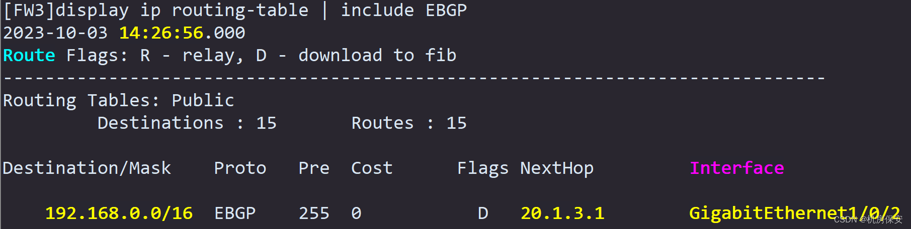
- Since the global address segment needs to be published to the VPN, a static blackhole route to the Web-Server global address 100.1.1.1 needs to be configured on the firewall FW3 to guide the Web-Server's VPN traffic.
- Configure a default route on FW3 to guide the return traffic of the Web-Server from the data center to the corporate intranet.
Configuration process:
#FW1
[FW1]ip route-static 0.0.0.0 0.0.0.0 10.2.1.2
[FW1]ip route-static 100.1.1.1 255.255.255.255 10.2.2.2

#FW2
[FW2]ip route-static 0.0.0.0 0.0.0.0 10.3.1.2

#FW3
[FW3]ip route-static 100.1.1.1 32 NULL 0
[FW3]ip route-static 100.1.1.1 255.255.255.255 10.3.2.2
[FW3]ip route-static 0.0.0.0 0.0.0.0 20.1.3.1

#PE1
[PE1]ip route-static 192.168.2.0 24 10.2.1.1
[PE1]ip route-static 192.168.2.0 24 10.3.1.1
verify:


Task 7: Public network dynamic routing configuration
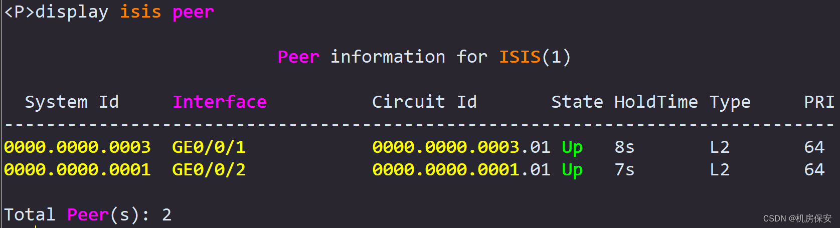
- Deploy the ISIS routing protocol in the WAN composed of PE1, P, and PE2. The process ID is 1, the ISIS domain is configured as Level-2, the area ID number is 01, and the systemid value is planned by yourself. It is required that Loopback0 and GE0/0/2 of PE1, Loopback0, GE0/0/1 and GE0/0/2 of the P router, and Loopback0 and GE0/0/1 of PE2 enable the ISIS protocol.
- In order to improve network security, you need to configure the MD5 authentication function for LSP, CSNP, and PSNP packets, and the authentication password is ICTEXAM.
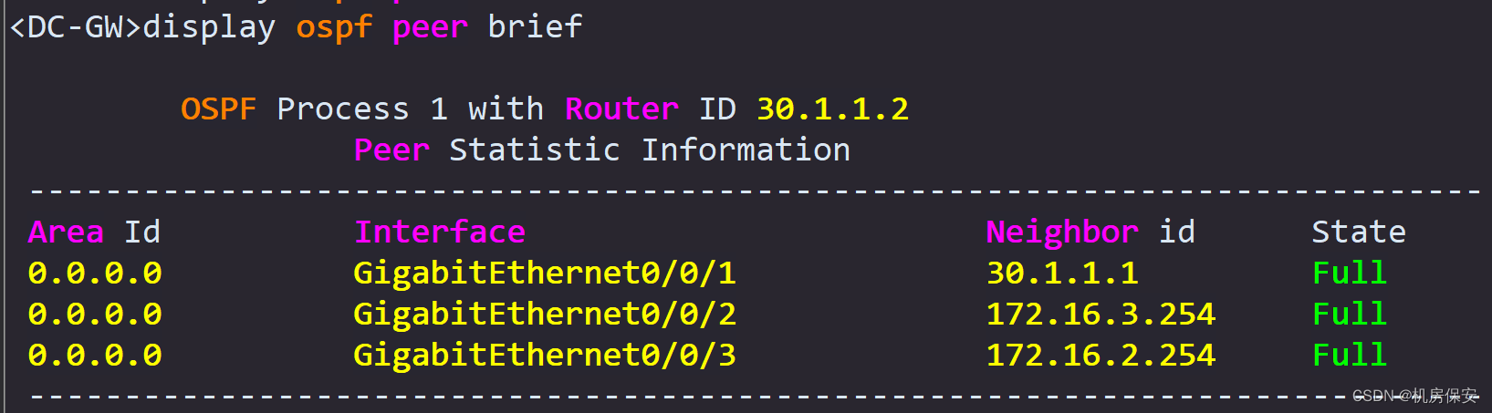
- OSPF is deployed in the DC data center. All routers in the DC are deployed in the ospf area 0 backbone area. GE1/0/1 of FW3 and loopback0, GE0/0/1, GE0/0/2 and GE0/0/ of DC-GW are required. 3. Publish the address segments of Leaf1's Loopback0, GE0/0/2 and GE0/0/3, and Leaf2's loopback0 and GE0/0/3 to the OSPF area.
- FW3 publishes the default route to the OSPF routing domain to guide the return traffic from the Web-Server server to the corporate intranet. It is required that when the link between FW3 and PE2 is interrupted, FW3 can stop advertising the default route synchronously to avoid invalid traffic.
- PE1's loopback0 and P router's loopback0 are configured as IBGP neighbors, PE2's loopback0 and P router's loopback0 are configured as IBGP neighbors, P router is configured with an IBGP neighbor group, PE1 and PE2 are added as neighbor group members, and P router is configured as a reflector RR. PE1 and PE2 are clients of P router. GE0/0/3 of PE2 and GE0/0/3 of the Internet router are configured as EBGP neighbors. Provide EBGP notification of the loopback0 address on the Internet router to the peer router PE2 to guide the traffic upstream. (Refer to Figure 2-2 and description for routing)
Configuration process:
任务7:公网动态路由配置
ISIS
#PE1
[PE1]isis 1
[PE1-isis-1]network-entity 01.0000.0000.0001.00
[PE1-isis-1]is-level level-2
[PE1-isis-1]domain-authentication-mode md5 ICTEXAM
[PE1]interface LoopBack 0
[PE1-LoopBack0]isis enable 1
[PE1]interface GigabitEthernet0/0/2
[PE1-GigabitEthernet0/0/2]isis enable 1

#P
[P]isis 1
[P-isis-1]network-entity 01.0000.0000.0002.00
[P-isis-1]is-level level-2
[PE1-isis-1]domain-authentication-mode md5 ICTEXAM
[P]interface LoopBack 0
[P-LoopBack0]isis enable 1
[P]interface GigabitEthernet0/0/1
[P-GigabitEthernet0/0/1]isis enable 1
[P]interface GigabitEthernet0/0/2
[P-GigabitEthernet0/0/2]isis enable 1


#PE2
[PE2]isis 1
[PE2-isis-1]network-entity 01.0000.0000.0003.00
[PE2-isis-1]is-level level-2
[PE1-isis-1]domain-authentication-mode md5 ICTEXAM
[PE2]interface LoopBack 0
[PE2-LoopBack0]isis enable 1
[PE2]interface GigabitEthernet0/0/1
[PE2-GigabitEthernet0/0/1]isis enable 1


OSPF
#FW3
[FW3]ospf 1
[FW3-ospf-1]default-route-advertise type 1
[FW3-ospf-1]area 0
[FW3-ospf-1-area-0.0.0.0]network 30.1.1.1 0.0.0.0

#DC-GW
[DC-GW]ospf 1
[DC-GW-ospf-1]area 0
[DC-GW-ospf-1-area-0.0.0.0]network 11.11.11.11 0.0.0.0
[DC-GW-ospf-1-area-0.0.0.0]network 30.1.1.2 0.0.0.0
[DC-GW-ospf-1-area-0.0.0.0]network 30.1.2.1 0.0.0.0
[DC-GW-ospf-1-area-0.0.0.0]network 30.1.3.1 0.0.0.0

#Leaf1
[Leaf1]ospf 1
[Leaf1-ospf-1]area 0
[Leaf1-ospf-1-area-0.0.0.0]network 12.12.12.12 0.0.0.0
[Leaf1-ospf-1-area-0.0.0.0]network 30.1.2.2 0.0.0.0
[Leaf1-ospf-1-area-0.0.0.0]network 172.16.1.254 0.0.0.0

#Leaf2
[Leaf2]ospf 1
[Leaf2-ospf-1]area 0
[Leaf2-ospf-1-area-0.0.0.0]network 30.1.3.2 0.0.0.0
[Leaf2-ospf-1-area-0.0.0.0]network 13.13.13.13 0.0.0.0

BGP
#PE1
[PE1]bgp 100
[PE1-bgp]peer 2.2.2.2 as-number 100
[PE1-bgp]peer 2.2.2.2 connect-interface LoopBack0

#P
[P]bgp 100
[P-bgp]group PE1-PE2 internal
[P-bgp]peer 1.1.1.1 group PE1-PE2
[P-bgp]peer 3.3.3.3 group PE1-PE2
[P-bgp]peer PE1-PE2 connect-interface LoopBack 0
[P-bgp]peer PE1-PE2 reflect-client

#PE2
[PE2]bgp 100
[PE2-bgp]peer 2.2.2.2 as-number 100
[PE2-bgp]peer 2.2.2.2 connect-interface LoopBack 0
[PE2-bgp]peer 20.1.4.2 as-number 200
[PE2-bgp]peer 20.1.3.2 as-number 300
[PE2-bgp]peer 2.2.2.2 next-hop-local

#Internet
[Internet]bgp 200
[Internet-bgp]peer 20.1.4.1 as-number 100
[Internet-bgp]network 16.16.16.16 32

#FW3
[Internet]bgp 300
[Internet-bgp]peer 20.1.3.1 as-number 100
[Internet-bgp]network 100.1.1.1 32
verify:


Task 8: MPLS VPN (refer to Figure 2-3 and description for routing)
- PE1's loopback0 and P router's Loopback0 are configured as MP-IBGP neighbors, PE2's loopback0 and P router's loopback0 are configured as MP-IBGP neighbors, P router is configured as VPN reflector vRR, PE1 and PE2 are clients of P router. In order to deliver the route smoothly, undo policy vpn-target needs to be configured on the P router.
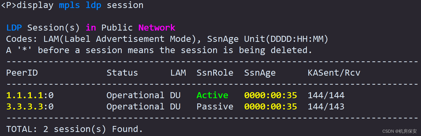
- PE1, P, and PE2 enable MPLS and MPLS LDP, and configure their respective loopback0 interface addresses as MPLS LSR IDs. GE0/0/2 of PE1, GE0/0/1 and GE0/0/2 of the P router, and FE0/0/1 of PE2 all enable MPLS and MPLS LDP.
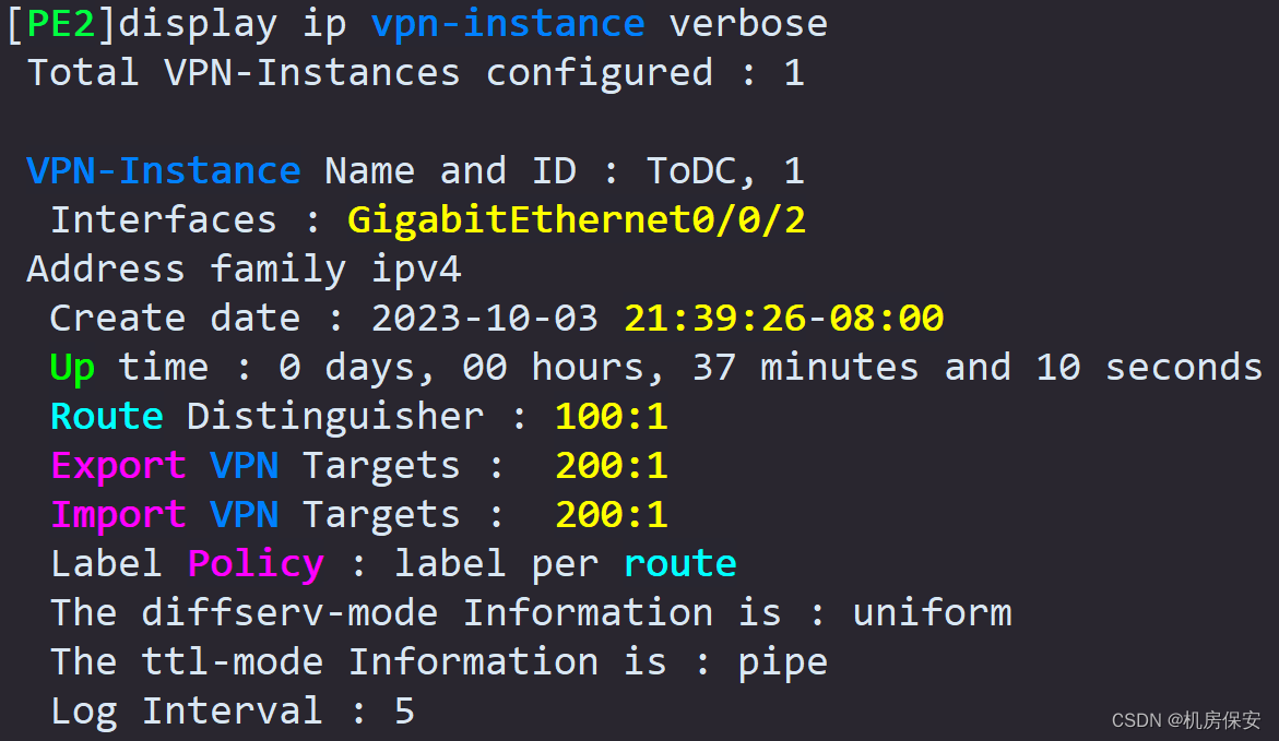
- PE1 and PE2 configure VPN instances, named ToDC, RD value is 100:1, Export RT and Import RT are both 200:1. Bind the GE0/0/3.1 interface of PE1 to the VPN instance ToDC of PE1, and bind the GE0/0/2 of PE2 to the VPN instance ToDC of PE2.
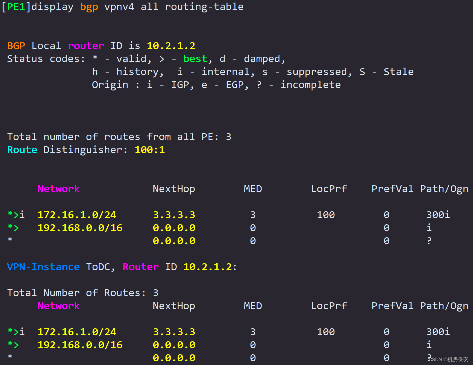
- Configure a static route in the VPN instance ToDC of PE1. The destination network segment is the Web-Client address segment 192.168.0.0/16, which points to GE1/0/3.1 of FW1 and FW2 to achieve load balancing of the Web-Server return traffic. . Import the two configured equal-cost static routes into the VPN instance ToDC, and let MP-IBGP advertise them to PE2 to guide the backhaul traffic of the Web-Server.
- Interface GE0/0/2 on PE2's VPN instance ToDC and FW3's GE1/0/2 are configured as EBGP neighbors, and Web-Server service routes are exchanged through EBGP neighbors.
任务8:MPLS VPN配置
VPN实例
#PE1
[PE1]ip vpn-instance ToDC
[PE1-vpn-instance-ToDC]route-distinguisher 100:1
[PE1-vpn-instance-ToDC-af-ipv4]vpn-target 200:1 both
[PE1]interface GigabitEthernet0/0/3.1
[PE1-GigabitEthernet0/0/3.1]ip binding vpn-instance ToDC
[PE1-GigabitEthernet0/0/3.1]ip address 10.3.2.2 30
[PE1]interface GigabitEthernet0/0/1.1
[PE1-GigabitEthernet0/0/1.1]ip binding vpn-instance ToDC
[PE1-GigabitEthernet0/0/1.1]ip address 10.2.2.2 30

#PE2
[PE2]ip vpn-instance ToDC
[PE2-vpn-instance-ToDC]route-distinguisher 100:1
[PE2-vpn-instance-ToDC-af-ipv4]vpn-target 200:1 both
[PE2]interface GigabitEthernet0/0/2
[PE2-GigabitEthernet0/0/2]ip binding vpn-instance ToDC
[PE2-GigabitEthernet0/0/2]ip address 20.1.3.1 30

MPLS
#PE1
[PE1]mpls lsr-id 1.1.1.1
[PE1]mpls
[PE1]mpls ldp
[PE1]interface GigabitEthernet0/0/2
[PE1-GigabitEthernet0/0/2]mpls
[PE1-GigabitEthernet0/0/2]mpls ldp

#P
[P]mpls lsr-id 2.2.2.2
[P]mpls
[P]mpls ldp
[P]interface GigabitEthernet0/0/1
[P-GigabitEthernet0/0/1]mpls
[P-GigabitEthernet0/0/1]mpls ldp
[P]interface GigabitEthernet0/0/2
[P-GigabitEthernet0/0/2]mpls
[P-GigabitEthernet0/0/2]mpls ldp

#PE2
[PE2]mpls lsr-id 3.3.3.3
[PE2]mpls
[PE2]mpls ldp
[PE2]interface GigabitEthernet0/0/1
[PE2-GigabitEthernet0/0/1]mpls
[PE2-GigabitEthernet0/0/1]mpls ldp

MP-BGP
#PE1
[PE1]bgp 100
[PE1-bgp]ipv4-family vpnv4
[PE1-bgp-af-vpnv4]peer 2.2.2.2 enable

#P
[P]bgp 100
[P-bgp]ipv4-family vpnv4
[P-bgp-af-vpnv4]undo policy vpn-target
[P-bgp-af-vpnv4]peer 1.1.1.1 enable
[P-bgp-af-vpnv4]peer 3.3.3.3 enable
[P-bgp-af-vpnv4]peer 1.1.1.1 reflect-client
[P-bgp-af-vpnv4]peer 3.3.3.3 reflect-client

#PE2
[PE2-bgp]ipv4-family vpn-instance ToDC
[PE2-bgp-ToDC]peer 20.1.3.2 as-number 300
[PE2-bgp]ipv4-family vpnv4
[PE2-bgp-af-vpnv4]peer 2.2.2.2 enable
[PE2-bgp-af-vpnv4]peer 2.2.2.2 next-hop-local


VPN静态路由
#PE1
[PE1]ip route-static vpn-instance ToDC 192.168.0.0 16 10.2.2.1
[PE1]ip route-static vpn-instance ToDC 192.168.0.0 16 10.3.2.1
[PE1]bgp 100
[PE1-bgp]ipv4-family vpn-instance ToDC
[PE1-bgp-ToDC]network 10.3.2.0 30
[PE1-bgp-ToDC]network 192.168.0.0 16
verify:

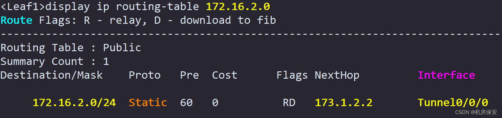
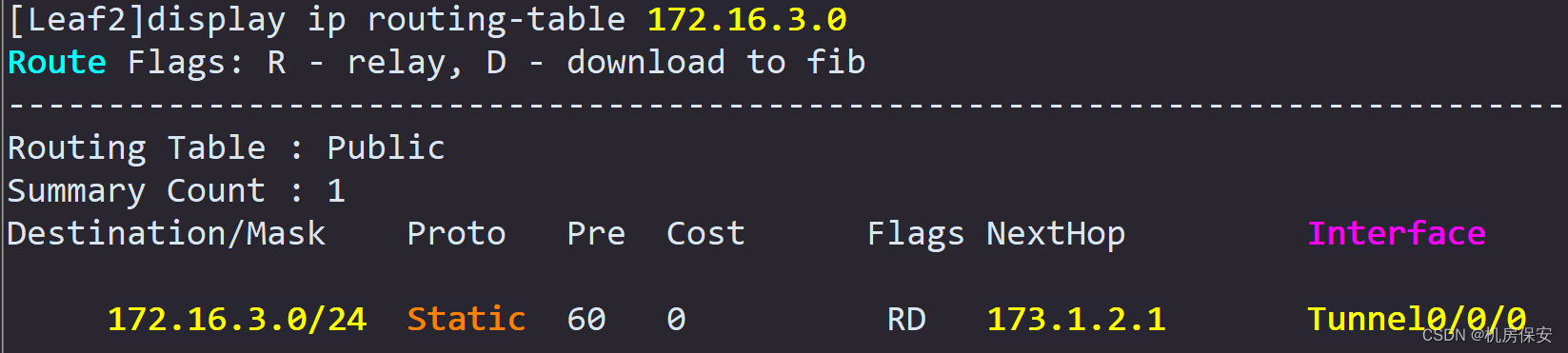
Task 9: GRE
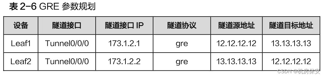
- Tenants in the data center will deploy a virtual private network. The virtual private network is divided into two subnets. VM1 belongs to subnet 1 (172.16.3.0/24) and VM2 belongs to subnet 2 (172.16.2.0/24). In order to realize that the data center is located For virtual machines in two different subnets to communicate, GRE needs to be deployed between the gateway Leaf of VM1 and the gateway Leaf2 of VM2. Complete the GRE tunnel configuration according to the parameter plan in Table 2-6.
Configuration process:
任务9:GRE
#Leaf1
[Leaf1]interface Tunnel 0/0/0
[Leaf1-Tunnel0/0/0]tunnel-protocol gre
[Leaf1-Tunnel0/0/0]ip address 173.1.2.1 30
[Leaf1-Tunnel0/0/0]source 12.12.12.12
[Leaf1-Tunnel0/0/0]destination 13.13.13.13
[Leaf1]ip route-static 172.16.2.0 24 173.1.2.2

#Leaf2
[Leaf2]interface Tunnel 0/0/0
[Leaf2-Tunnel0/0/0]tunnel-protocol gre
[Leaf2-Tunnel0/0/0]ip address 173.1.2.2 30
[Leaf2-Tunnel0/0/0]source 13.13.13.13
[Leaf2-Tunnel0/0/0]destination 12.12.12.12
[Leaf2]ip route-static 172.16.3.0 24 173.1.2.1
verify:
Task 10: WLAN
Ⅰ. Wired side network configuration
- Complete the switch side configuration of the enterprise intranet so that the AP can communicate with the AC. The terminal under the AP can communicate with the gateway (firewall) after connecting to the WLAN network.
- Complete the underlying network configuration on the AC side so that the AC can communicate with the AP. The AC serves as a DHCP server and allocates IP addresses to the AP and Station respectively.
Ⅱ.WLAN business configuration
- The service requirements on the WLAN side are as follows: the AP and AC are in the same network segment, the AP directly registers with the AC at Layer 2, the AP forwards station traffic through the AC, and the AC serves as the DHCP server for the AP and station.
- The wireless side service configuration is planned according to Table 2-8:
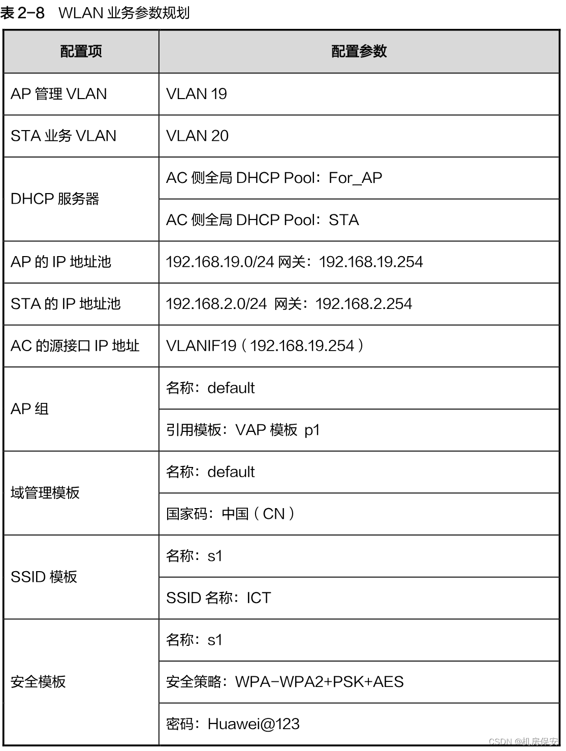
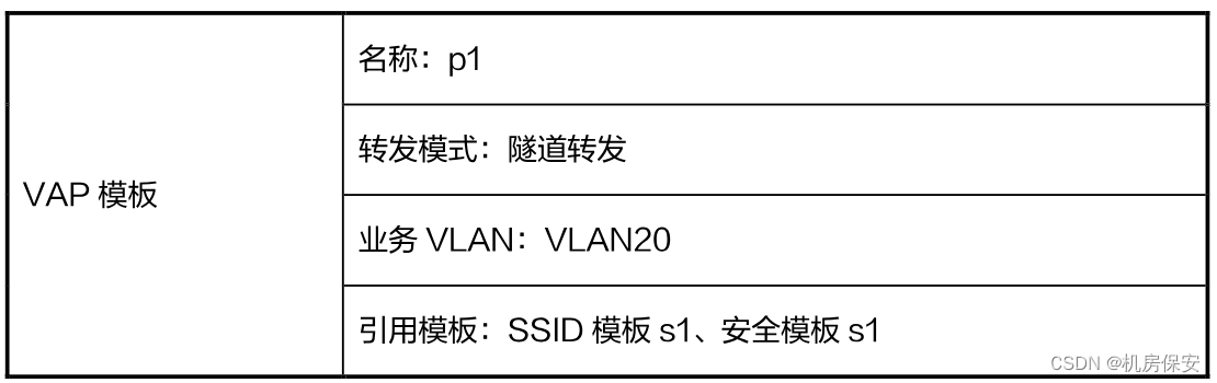
Configuration process:
任务10:WLAN
DHCP
#AC1
[AC]interface Vlanif 19
[AC-Vlanif19]ip address 192.168.19.254 24
[AC]dhcp enable
[AC]ip pool For_AP
[AC-ip-pool-For_AP]network 192.168.19.0 mask 255.255.255.0
[AC-ip-pool-For_AP]gateway-list 192.168.19.254
[AC]ip pool STA
[AC-ip-pool-STA]network 192.168.2.0 mask 255.255.255.0
[AC-ip-pool-STA]gateway-list 192.168.2.254
[AC]interface Vlanif 19
[AC-Vlanif19]dhcp select global
[AC]interface Vlanif 20
[AC-Vlanif20]dhcp select global
[AC]interface Vlanif 19
[AC-Vlanif19]ip address 192.168.19.254 24
WLAN业务配置
[AC]capwap source interface Vlanif 19
[AC]wlan
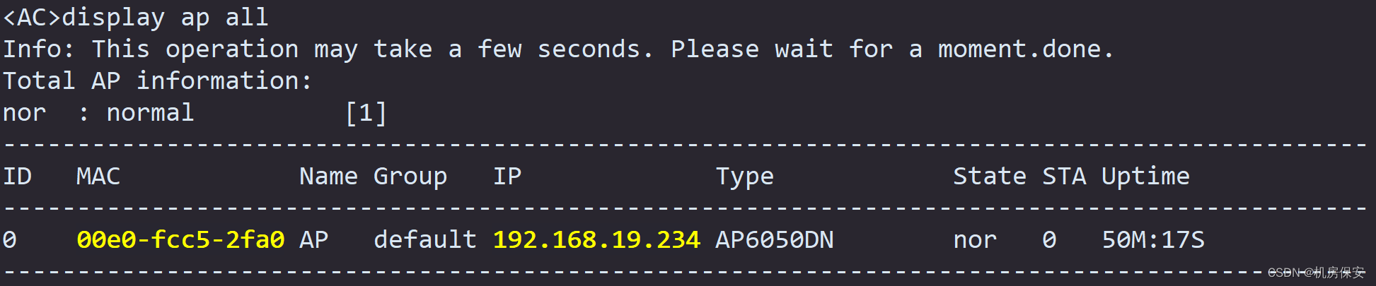
[AC-wlan-view]ap auth-mode mac-auth
[AC-wlan-view]ap-id 0 ap-mac 00e0-fc52-0650
[AC-wlan-ap-0]ap-name AP
[AC-wlan-ap-0]ap-group default
[AC-wlan-view]ssid-profile name s1
[AC-wlan-ssid-prof-s1]ssid ICT
[AC-wlan-view]security-profile name s1
[AC-wlan-sec-prof-s1]security wpa-wpa2 psk pass-phrase Huawei@123 aes
[AC-wlan-view]vap-profile name p1
[AC-wlan-vap-prof-p1]forward-mode tunnel
[AC-wlan-vap-prof-p1]service-vlan vlan-id 20
[AC-wlan-vap-prof-p1]ssid-profile s1
[AC-wlan-vap-prof-p1]security-profile s1
[AC-wlan-view]ap-group name default
[AC-wlan-ap-group-default]regulatory-domain-profile default
[AC-wlan-ap-group-default]vap-profile p1 wlan 1 radio all verify: