1 Protocolo del puerto serie
El nombre completo del puerto serie es Receptor y Transmisor Asíncrono Universal, que se utiliza principalmente para la transmisión de datos en serie y es un modo de transmisión full-duplex. Convierte datos paralelos en datos en serie para su transmisión al enviar datos y convierte los datos en serie recibidos en datos paralelos al recibir datos.
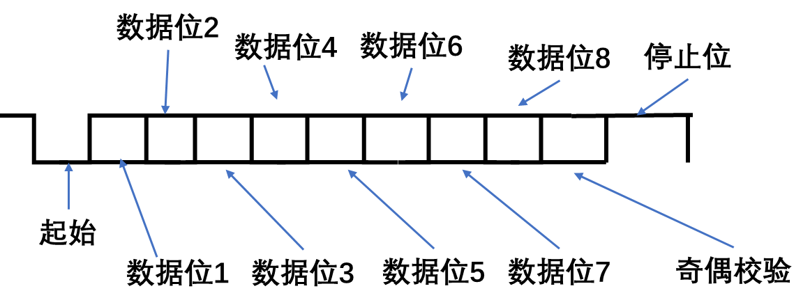
Una trama de datos durante la transmisión o recepción UART consta de 4 partes, incluidos bits de inicio, bits de datos, bits de paridad y bits de parada. El bit de inicio marca el comienzo de un cuadro de datos y el bit de parada marca el final de un cuadro de datos. Los bits de datos son datos válidos en un marco de datos y los bits de paridad se pueden dividir en paridad impar o paridad par.
Bit de inicio:
la señal de transmisión tx es baja por defecto. Cuando ocurre un flanco descendente y el nivel bajo dura un bit, se considera que se ha transmitido un bit de inicio.
Los bits de datos
son datos válidos para la transmisión y se puede seleccionar el ancho de bits de los datos, 6, 7 u 8 bits.
Dígito de control:
la exactitud de los datos transmitidos se puede comprobar hasta cierto punto.
Bit de parada:
si el nivel alto dura mucho tiempo, se considera como el final de los datos.
Como se muestra a continuación: (El ancho de bits de datos es un byte)
Velocidad de baudios
: La velocidad de baudios indica cuántos bits de datos deben transmitirse en un segundo. Por ejemplo, 9600 bps significa que deben transmitirse 9600 bits en un segundo.
Módulo de envío de 2 puertos serie

Interpretación de señales:
| clc | reloj |
|---|---|
| primero_n | reiniciar |
| datos_tx | Un byte de datos enviado |
| tx_es | La señal de habilitación para enviar datos es un pulso alto. |
| byte_finish | Transmitió exitosamente un byte de datos |
| tx | señal enviada |
La idea general del diseño La
idea general es diseñar una máquina de estados con cinco estados, estado inactivo (IDLE), estado de inicio (START), envío de datos (SEND_DATA), verificación (EVEN_ODD_CHECK) y parada (STOP).
Primero, coloque los datos globales en un archivo config.v, el código es el siguiente:
`define CLK_FRE 50_000_000      //输入的时钟频率
`define BAUD_RATE 115200          //波特率
`define EVEN_CHECK 1            //1 :偶校验  0:奇校验
El código del módulo de uart_tx es el siguiente:
`include "config.v"
module uart_tx (
    input   wire                    clk         ,
    input   wire                    rst_n       ,
    input   wire    [7:0]           tx_data     ,
    input   wire                    tx_en       ,

    output  wire                    byte_finish ,
    output  reg                     tx
);

    localparam      IDLE            =   5'b00001    ,       //空闲
                    START           =   5'b00010    ,       //起始
                    SEND_DATA       =   5'b00100    ,       //发送数据
                    EVEN_OLD_CHECK  =   5'b01000    ,       //奇偶校验
                    STOP            =   5'b10000    ;       //停止


    localparam      CNT_MAX         =   `CLK_FRE / `BAUD_RATE ;

    reg     [31:0]  cnt         ;
    reg     [4:0]   state       ;
    reg     [4:0]   nx_state    ;
    reg     [2:0]   cnt_data    ;
    reg             even_check  ;
    reg             odd_check   ;

    wire            start_finish;       //起始位结束信号
    wire            bit_flag    ;       //发送每个数据的bit信号
    wire            byte_flag   ;       //成功发送一字节数据的标致
    wire            check_flag  ;       //奇偶校验的标志
    wire            stop_flag   ;       //停止位的标志
    wire            check       ;       //要发送的奇偶校验信号


    assign start_finish = (state == START) && (cnt == CNT_MAX - 1) ? 1'b1 : 1'b0;
    assign bit_flag     = (state == SEND_DATA) && (cnt == CNT_MAX - 1) ? 1'b1 : 1'b0;
    assign byte_flag    = bit_flag && (cnt_data == 3'd7) ? 1'b1 : 1'b0;
    assign check_flag = ((state == EVEN_OLD_CHECK) && (cnt == CNT_MAX - 1)) ? 1'b1 : 1'b0;
    assign stop_flag = ((state == STOP) && (cnt == CNT_MAX - 1)) ? 1'b1 : 1'b0;
    assign check = `EVEN_CHECK ? even_check : odd_check;
    //状态转移(时序逻辑)
    always @(posedge clk or negedge rst_n) begin
        if(!rst_n) begin
            state <= IDLE;
        end
        else begin
            state <= nx_state;
        end
    end

    //状态跳转(组合逻辑)
    always @(*) begin
        //nx_state <= IDLE;
        case(state)
            IDLE:       nx_state = (tx_en) ? START : IDLE;
            START:      nx_state =  (start_finish) ? SEND_DATA : START;
            SEND_DATA:  nx_state = byte_flag ? EVEN_OLD_CHECK : SEND_DATA;
            EVEN_OLD_CHECK: nx_state = check_flag ? STOP : EVEN_OLD_CHECK;
            STOP:       nx_state = stop_flag ? IDLE : STOP;
            default:    nx_state = IDLE;
        endcase
    end
    //对cnt计数器赋值
    always @(posedge clk or negedge rst_n) begin
        if(!rst_n) begin
            cnt <= 'd0;
        end
        else begin
            case(state)
            IDLE:       cnt <= 'd0;
            START:  begin
                        if(nx_state == START) begin
                            cnt <= cnt + 1'b1;
                        end
                        else if(nx_state == SEND_DATA) begin
                            cnt <= 'd0;
                        end
                        else begin
                            cnt <= cnt;
                        end
                    end
            SEND_DATA:begin
                        if(nx_state == SEND_DATA) begin
                            if(bit_flag) begin
                                cnt <= 'd0;
                            end
                            else begin
                                cnt <= cnt + 1'b1;
                            end
                        end
                        else if(nx_state == EVEN_OLD_CHECK) begin
                            cnt <= 'd0;
                        end
                        else begin
                            cnt <= cnt;
                        end
                    end
            EVEN_OLD_CHECK: cnt <= (nx_state == EVEN_OLD_CHECK) ? cnt + 1'b1 : (nx_state == STOP) ? 'd0 : cnt;
            STOP:   cnt <= (nx_state == STOP) ? cnt + 1'b1 : 1'b0;
            default:cnt <= 'd0;
            endcase
        end
    end
    //统计发送的数据的bit数
    always @(posedge clk or negedge rst_n) begin
        if(!rst_n) begin
            cnt_data <= 3'd0;
        end
        else if((state == SEND_DATA) && (cnt_data == 3'd7) && (bit_flag)) begin
            cnt_data <= 'd0;
        end
        else if((state == SEND_DATA) && (cnt_data < 3'd7) && (bit_flag)) begin
            cnt_data <= cnt_data + 1'b1;
        end
        else begin
            cnt_data <= cnt_data;
        end
    end
    //生成奇校验还是偶校验
    always @(posedge clk or negedge rst_n) begin
        if(!rst_n) begin
            even_check <= 1'b0;
            odd_check <= 1'b0;
        end
        else if(tx_en) begin
            even_check <= ^tx_data;
            odd_check  <= ~(^tx_data);
        end
        else begin
            even_check <= even_check;
            odd_check <= odd_check;
        end
    end
    assign byte_finish = stop_flag;
    //发送数据
    always @(posedge clk or negedge rst_n) begin
        if(!rst_n) begin
            tx <= 1'b1;
        end
        else begin
            case(nx_state)
                IDLE:       tx <= 1'b1;
                START:      tx <= 1'b0;
                SEND_DATA:  tx <= bit_flag ? tx_data[cnt_data+1] : tx_data[cnt_data];
                EVEN_OLD_CHECK:tx <= check;
                STOP:       tx <= 1'b1;
                default:    tx <= 1'b1;
            endcase
        end
    end


endmodule
El banco de pruebas es el siguiente:
`timescale 1ns/1ns
`define CLK_CYCLE 20

module tb_uart_tx;

    reg         clk         ;
    reg         rst_n       ;
    reg  [7:0]  tx_data     ;
    reg         tx_en       ;

    wire        byte_finish ;
    wire        tx          ;

    uart_tx     u_uart_tx(
    .  clk          (clk),
    .  rst_n        (rst_n),
    .  tx_data      (tx_data),
    .  tx_en        (tx_en),

    .  byte_finish  (byte_finish),
    .  tx           (tx)
);

initial begin
     clk = 1'b0;
     rst_n = 1'b0;
     tx_data = 8'h00;
     tx_en = 1'b0;
     #30
     rst_n = 1'b1;
     #100
     repeat (2) @(posedge clk);
     tx_en = 1'b1;
     tx_data = 8'h45;
     @(posedge clk);
     tx_en = 1'b0;
     @(negedge byte_finish);
     tx_en = 1'b1;
     tx_data = 8'h23;
     @(posedge clk);
     tx_en = 1'b0;
     @(byte_finish);
     #100
     $finish;
end

always #(`CLK_CYCLE / 2) clk = ~clk;

endmodule
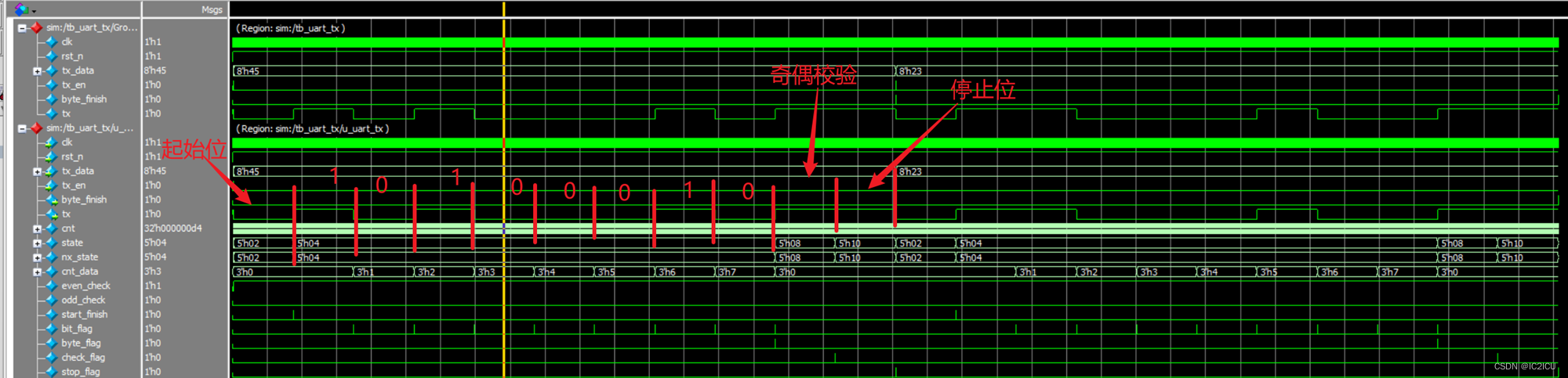
La forma de onda de simulación es la siguiente, que muestra que los datos se transmitieron exitosamente.
Módulo receptor de 3 puertos serie
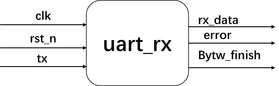
Interpretación de señales:
| clc | reloj |
|---|---|
| primero_n | reiniciar |
| tx | Señal de un solo bit recibida |
| datos_rx | Un byte de datos recibidos. |
| byte_finish | Señal de finalización de la recepción de datos de un byte. |
| error | Según la verificación de paridad, se juzga si los datos recibidos son creíbles. |
La idea general del diseño La
idea general es diseñar una máquina de estados con cinco estados, estado inactivo (IDLE), estado de inicio (START), recepción de datos (RV_DATA), verificación (CHECK) y parada (STOP). Cabe señalar que, para el muestreo de datos, se selecciona una señal de bits para ser muestreada en el medio, de modo que los datos muestreados sean más confiables.
Los módulos de uart_rx son los siguientes:
`include "config.v"

module uart_rx(
    input   wire                clk         ,
    input   wire                rst_n       ,
    input   wire                tx          ,

    output  wire    [7:0]       rx_data     ,
    output  reg                 error       ,
    output  wire                byte_finish
);

    localparam      IDLE    =       5'b00001    ,       //空闲
                    START   =       5'b00010    ,       //开始
                    RV_DATA =       5'b00100    ,       //接收数据
                    CHECK   =       5'b01000    ,       //奇偶校验
                    STOP    =       5'b10000    ;       //停止

    localparam      CNT_MAX     =   `CLK_FRE / `BAUD_RATE ;

    reg                     tx_dly      ;
    reg         [31:0]      cnt         ;
    reg         [4:0]       state       ;
    reg         [4:0]       nx_state    ;
    reg         [2:0]       cnt_bit     ;
    reg         [7:0]       rv_data     ;
    reg                     even_check  ;
    reg                     odd_check   ;

    wire                    tx_negedge  ;
    wire                    start_end   ;
    wire                    bit_flag    ;
    wire                    rv_end      ;
    wire                    sample_flag ;               //采样数据的信号
    wire                    check       ;
    wire                    check_end   ;
    wire                    stop_end    ;

    assign      start_end = (state == START) && (cnt == CNT_MAX - 2);

    assign      bit_flag = (state == RV_DATA) && (cnt == CNT_MAX - 1);

    assign      rv_end = (state == RV_DATA) && (bit_flag) && (cnt_bit == 3'd7);

    assign      sample_flag = ((state == RV_DATA) ) && (cnt == CNT_MAX / 2 - 1);

    assign      check = `EVEN_CHECK ? even_check : odd_check;

    assign      check_end = (state == CHECK) && (cnt == CNT_MAX - 1);

    assign      stop_end = (state == STOP) && (cnt == CNT_MAX - 1);

    always @(posedge clk or negedge rst_n) begin
        if(!rst_n) begin
            tx_dly <= 1'b1;
        end
        else begin
            tx_dly <= tx;
        end
    end

    assign  tx_negedge = ((tx_dly) && (!tx)) ? 1'b1 : 1'b0;

    always @(posedge clk or negedge rst_n) begin
        if(!rst_n) begin
            state <= IDLE;
        end
        else begin
            state <= nx_state;
        end
    end

    always @(*) begin
        case(state)
            IDLE:   nx_state = tx_negedge ? START : IDLE;
            START:  nx_state = start_end ? RV_DATA : START;
            RV_DATA:nx_state = rv_end ? CHECK : RV_DATA;
            CHECK:  nx_state = check_end ? STOP : CHECK;
            STOP:   nx_state = stop_end ? IDLE : STOP;
            default:nx_state = IDLE;
        endcase
    end

    always @(posedge clk or negedge rst_n) begin
        if(!rst_n) begin
            cnt <= 'd0;
        end
        else begin
            case(state)
            IDLE:       cnt <= 'd0;
            START:  begin
                        if(nx_state == START) begin
                            cnt <= cnt + 1'b1;
                        end
                        else if(nx_state == RV_DATA) begin
                            cnt <= 'd0;
                        end
                        else begin
                            cnt <= cnt;
                        end
                    end
            RV_DATA:begin
                        if(nx_state == RV_DATA) begin
                            if(bit_flag) begin
                                cnt <= 'd0;
                            end
                            else begin
                                cnt <= cnt + 1'b1;
                            end
                        end
                        else if(nx_state == CHECK) begin
                            cnt <= 'd0;
                        end
                        else begin
                            cnt <= cnt;
                        end
                    end
            CHECK:  cnt <= (nx_state == CHECK) ? cnt + 1'b1 : 'd0;
            STOP :  cnt <= (nx_state == STOP) ? cnt + 1'b1 : 'd0;
            default:cnt <= 'd0;
            endcase
        end
    end

    always @(posedge clk or negedge rst_n) begin
        if(!rst_n) begin
            cnt_bit <= 3'd0;
        end
        else if((bit_flag) && (nx_state == CHECK)) begin
            cnt_bit <= 3'd0;
        end
        else if(bit_flag) begin
            cnt_bit <= cnt_bit + 1'b1;
        end
        else begin
            cnt_bit <= cnt_bit;
        end
    end

    always @(posedge clk or negedge rst_n) begin
        if(!rst_n) begin
            rv_data <= 8'h00;
        end
        else if(state == IDLE) begin
            rv_data <= 8'h00;
        end
        else if(sample_flag) begin
            rv_data <= {

    tx, rv_data[7:1]};
        end
        else begin
            rv_data <= rv_data;
        end
    end

    always @(posedge clk or negedge rst_n) begin
        if(!rst_n) begin
            odd_check <= 1'b0;
            even_check <= 1'b0;
        end
        else if(nx_state == CHECK) begin
            even_check <= ^rv_data;
            odd_check <= ~(^rv_data);
        end
        else begin
            even_check <= even_check;
            odd_check <= odd_check;
        end
    end

    always @(posedge clk or negedge rst_n) begin
        if(!rst_n) begin
            error <= 1'b0;
        end
        else if(nx_state == IDLE) begin
            error <= 1'b0;
        end
        else if(nx_state == STOP) begin
            error <= 1'b0;
        end
        else if((nx_state == CHECK) && sample_flag) begin
            error <= (tx != check) ? 1'b1 : 1'b0;
        end
        else begin
            error <= error;
        end
    end

    assign rx_data = rv_data;

    assign byte_finish = (state == STOP) && (nx_state == IDLE);

endmodule
4 Co-simulación de módulos de envío y recepción de uart
La capa superior de uart es la siguiente:

el código del módulo uart es el siguiente, que sirve para conectar los módulos de envío y recepción
module uart(
    input   wire                clk         ,
    input   wire                rst_n       ,
    input   wire    [7:0]       tx_data     ,
    input   wire                tx_en       ,

    output  wire    [7:0]       rx_data     ,
    output  wire                error       ,
    output  wire                rv_byte_finish
);

    wire            tx_byte_finish  ;
    wire            tx              ;

    uart_tx     u_uart_tx(
    .  clk         (clk),
    .  rst_n       (rst_n),
    .  tx_data     (tx_data),
    .  tx_en       (tx_en),

    .  byte_finish (tx_byte_finish),
    .  tx (tx)
);

    uart_rx u_uart_rx(
    . clk         (clk),
    . rst_n       (rst_n),
    . tx          (tx),

    . rx_data     (rx_data),
    . error       (error),
    . byte_finish (rv_byte_finish)
);


endmodule
El código de simulación es el siguiente:
`timescale 1ns/1ns
`define CLK_CYCLE 20

module tb_uart;

    reg         clk         ;
    reg         rst_n       ;
    reg  [7:0]  tx_data     ;
    reg         tx_en       ;

    wire [7:0]  rx_data     ;
    wire        error       ;
    wire        rv_byte_finish;

    uart    u_uart(
    .   clk       (clk),
    .   rst_n     (rst_n),
    .   tx_data   (tx_data),
    .   tx_en     (tx_en),

    .   rx_data   (rx_data),
    .   error     (error),
    .   rv_byte_finish(rv_byte_finish)
);

    initial begin
     clk = 1'b0;
     rst_n = 1'b0;
     tx_data = 8'h00;
     tx_en = 1'b0;
     #30
     rst_n = 1'b1;
     #100
     repeat (2) @(posedge clk);
     tx_en = 1'b1;
     tx_data = 8'h45;
     @(posedge clk);
     tx_en = 1'b0;
     @(negedge rv_byte_finish);
     tx_en = 1'b1;
     tx_data = 8'h23;
     @(posedge clk);
     tx_en = 1'b0;
     @(rv_byte_finish);
     #100
     $finish;
end

always #(`CLK_CYCLE / 2) clk = ~clk;


endmodule
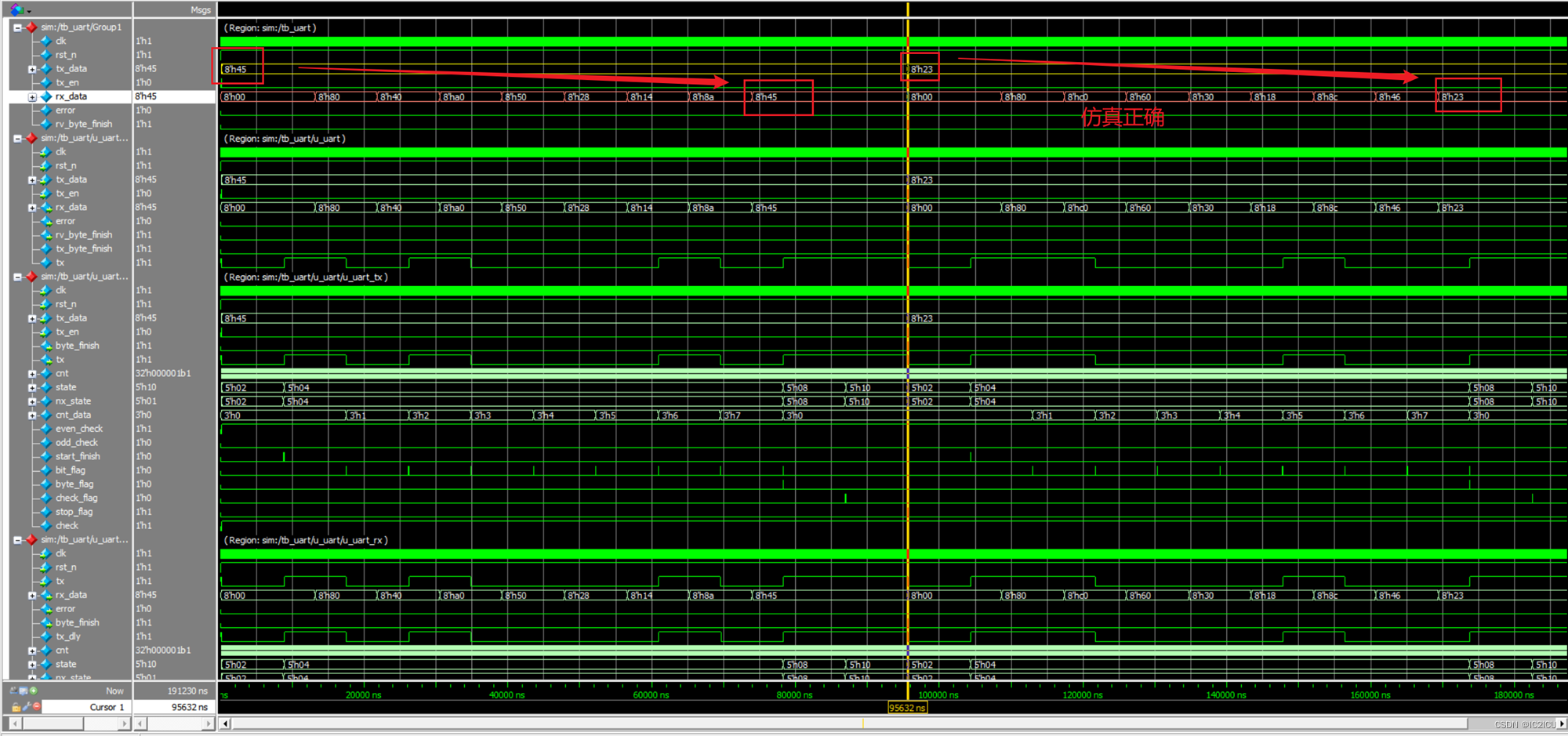
La forma de onda de simulación es la siguiente, se puede ver que los datos se recibieron con éxito.
5 resumen
Siento que tengo una mejor comprensión de la escritura y la comprensión de la máquina de estados. Hasta ahora, se han completado los tres protocolos de comunicación principales. ¡vamos vamos vamos! ! !