Directorio de artículos
objetivo de la misión
Utilice la placa de núcleo mínimo stm32 + módulo AHT20 para completar un dispositivo esclavo de temperatura y humedad con una interfaz modbus, que permite que la PC de la computadora superior obtenga temperatura y humedad a través del protocolo modbus. El programa principal adopta un marco multitarea, como RT-thread Nano.
material de tarea
Asistente en serie KEIL5
CubeMx modbuspoll STM32F103C8T6
Portabilidad de subprocesos RT
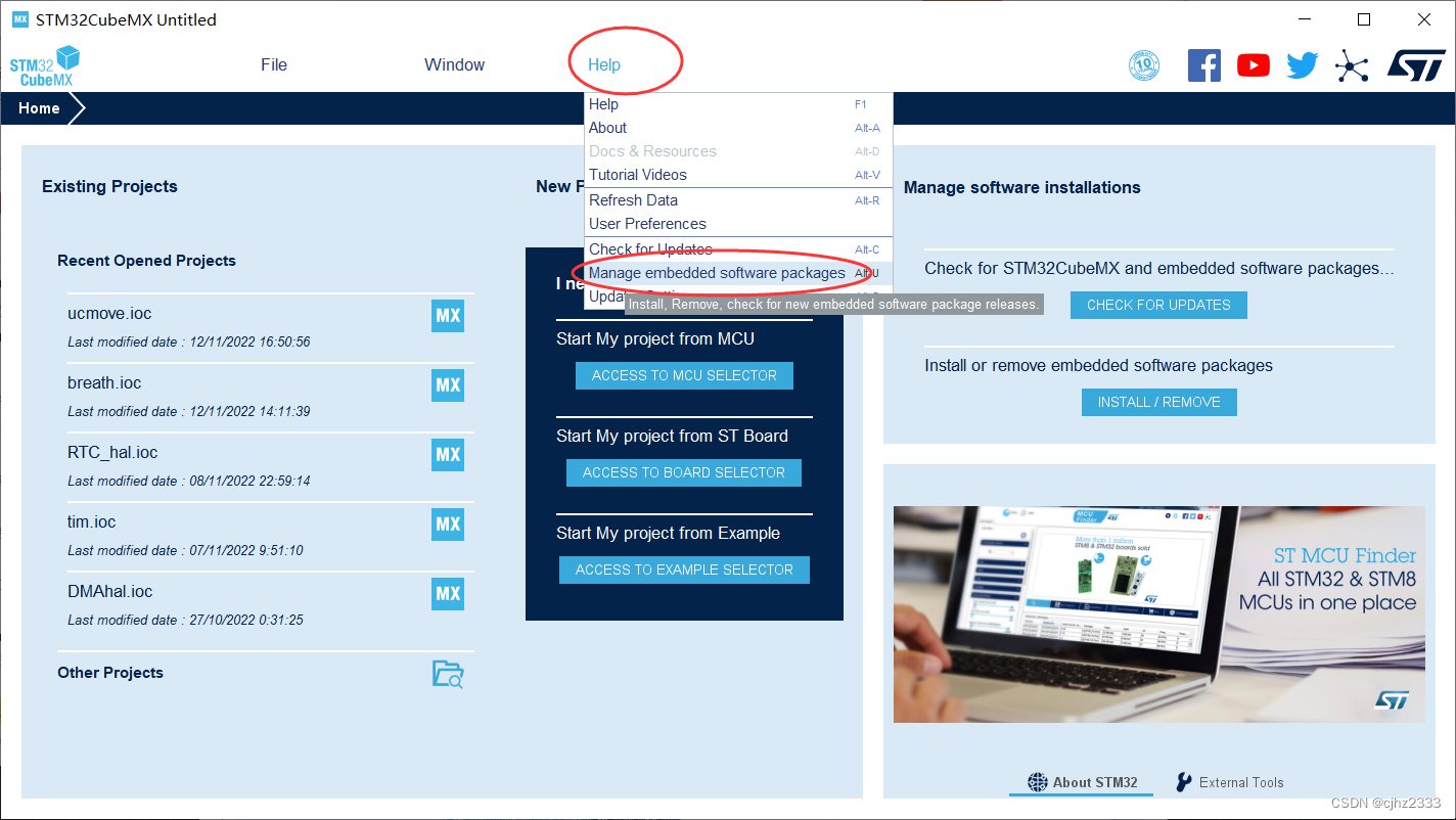
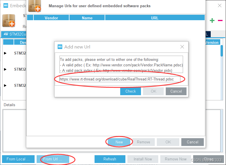
instalar cubemx
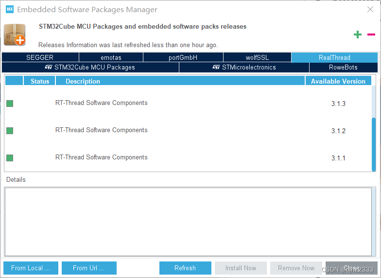
Cuando se complete la descarga, el cuadro frontal se volverá verde.
instalación de keil
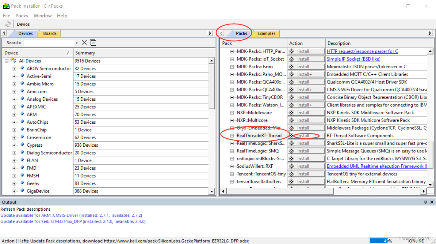
(1) Abra el software keil, haga clic en el instalador del paquete
(2) Siga la imagen para operar
Configuración de cubo
configuración del proyecto
Seleccione el chip STM32F103C8
, haga clic en paquetes de software, haga clic en seleccionar componentes
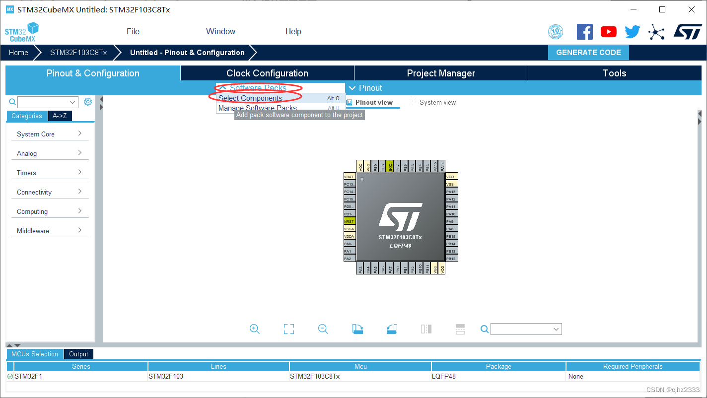
para seleccionar las tres versiones de 3.1.5 y luego haga clic en Aceptar
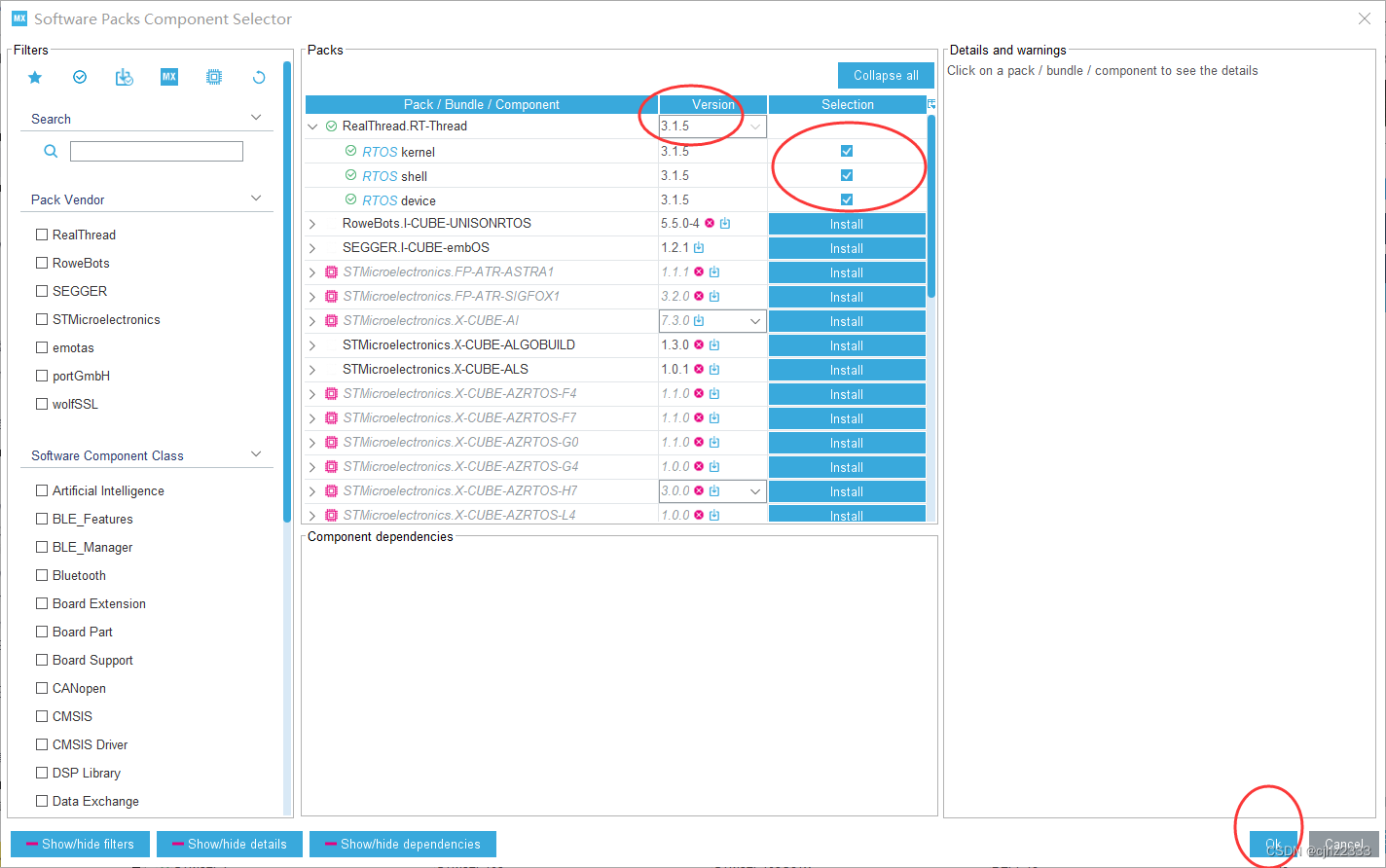
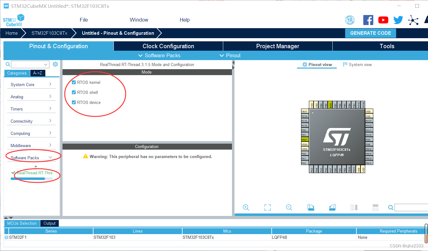
para verificar la siguiente
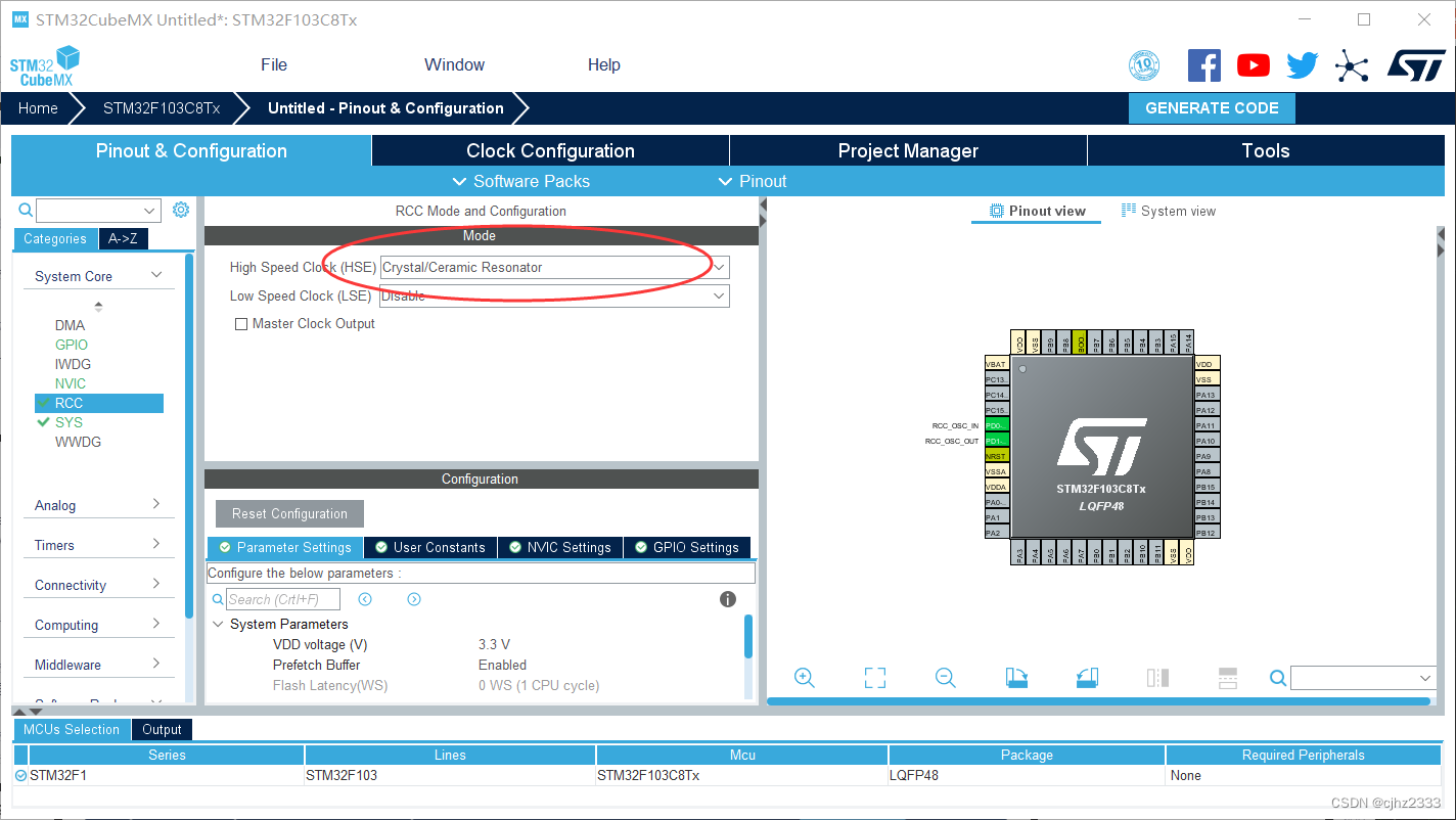
configuración RCC:
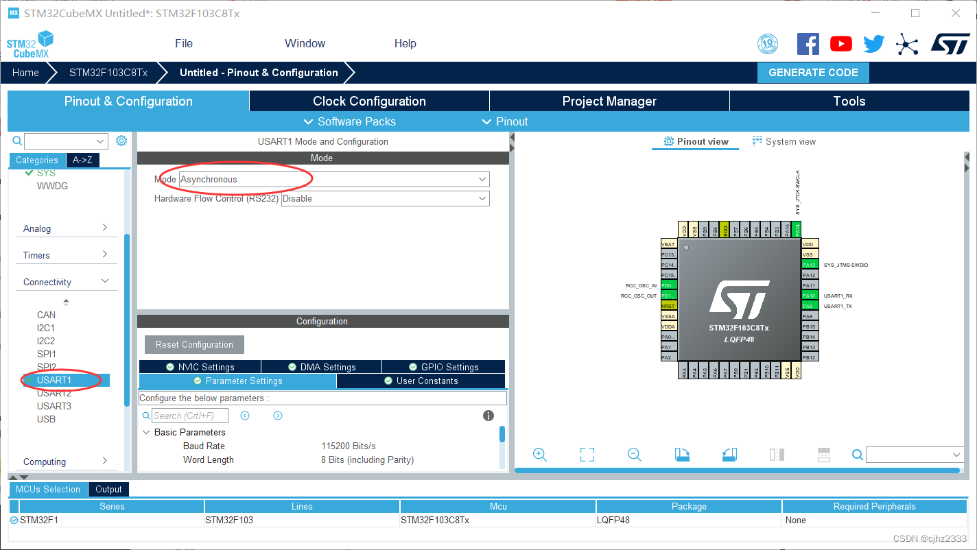
Configuración USART1:
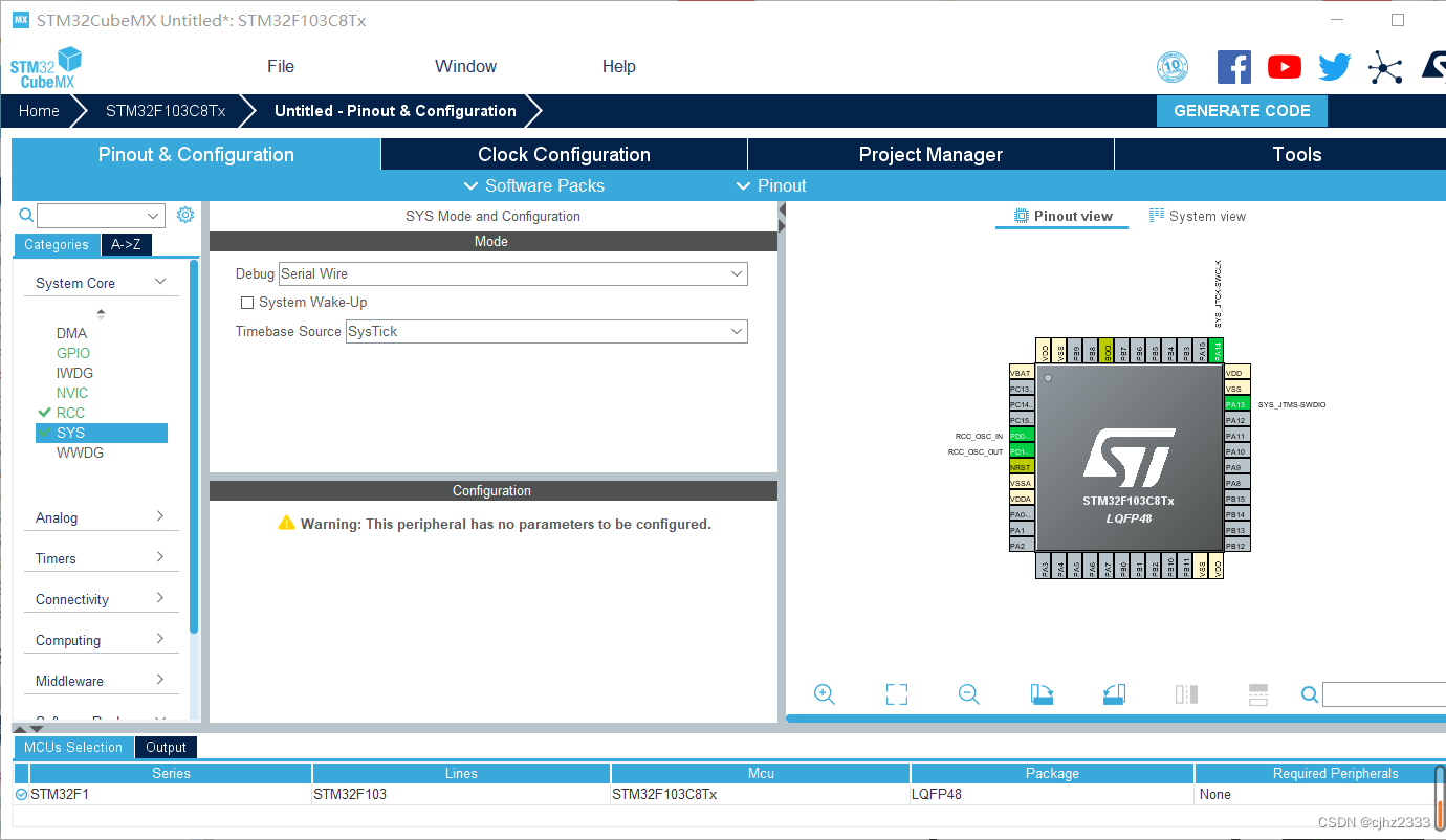
SYS:
GPIO: seleccione PC13, salida push-pull

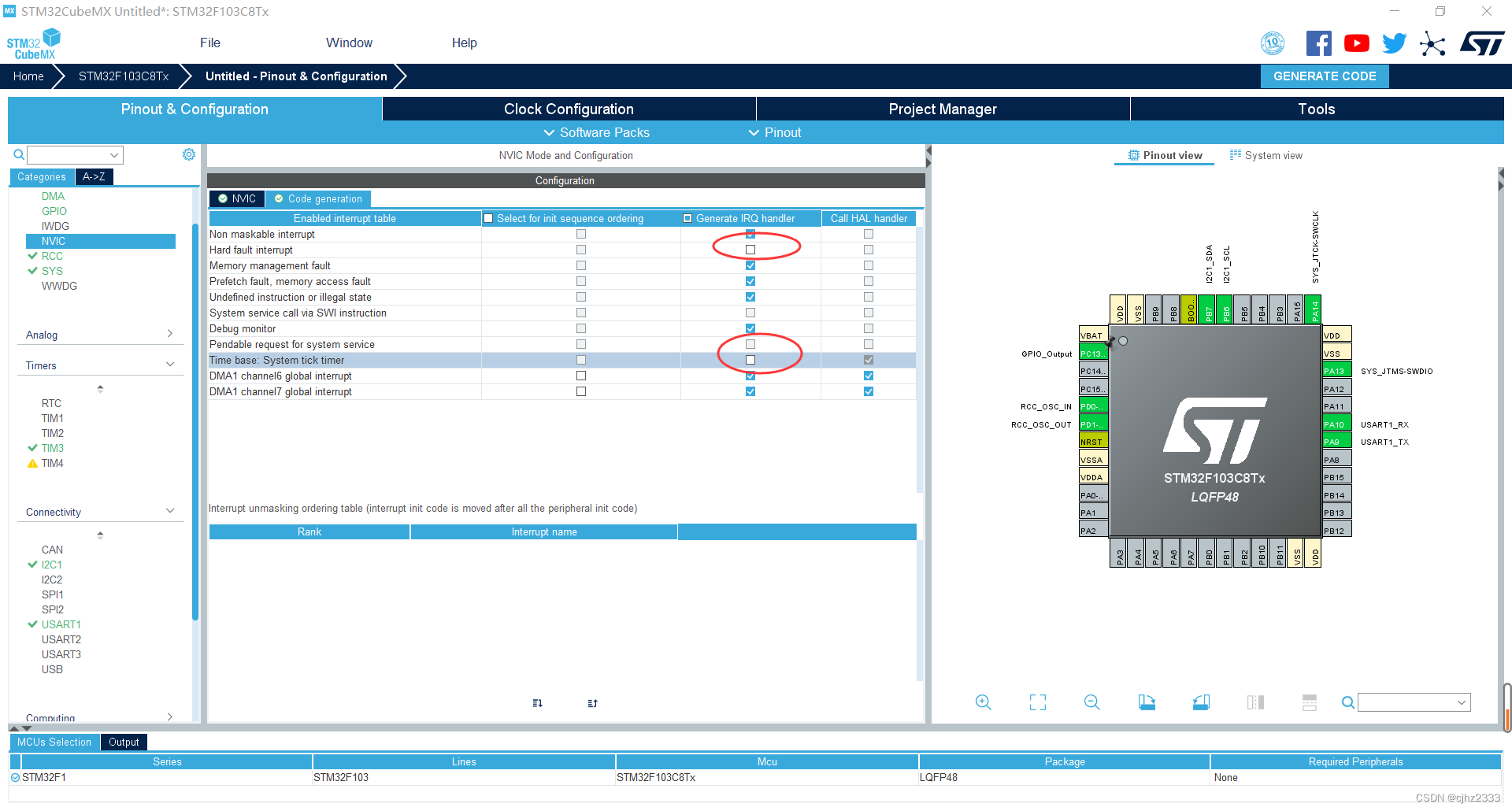
NVIC:
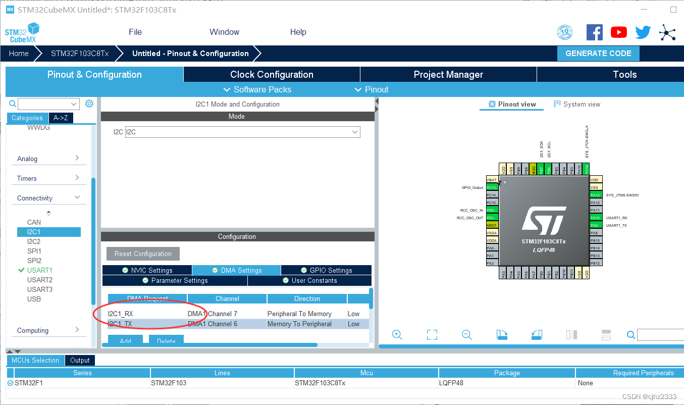
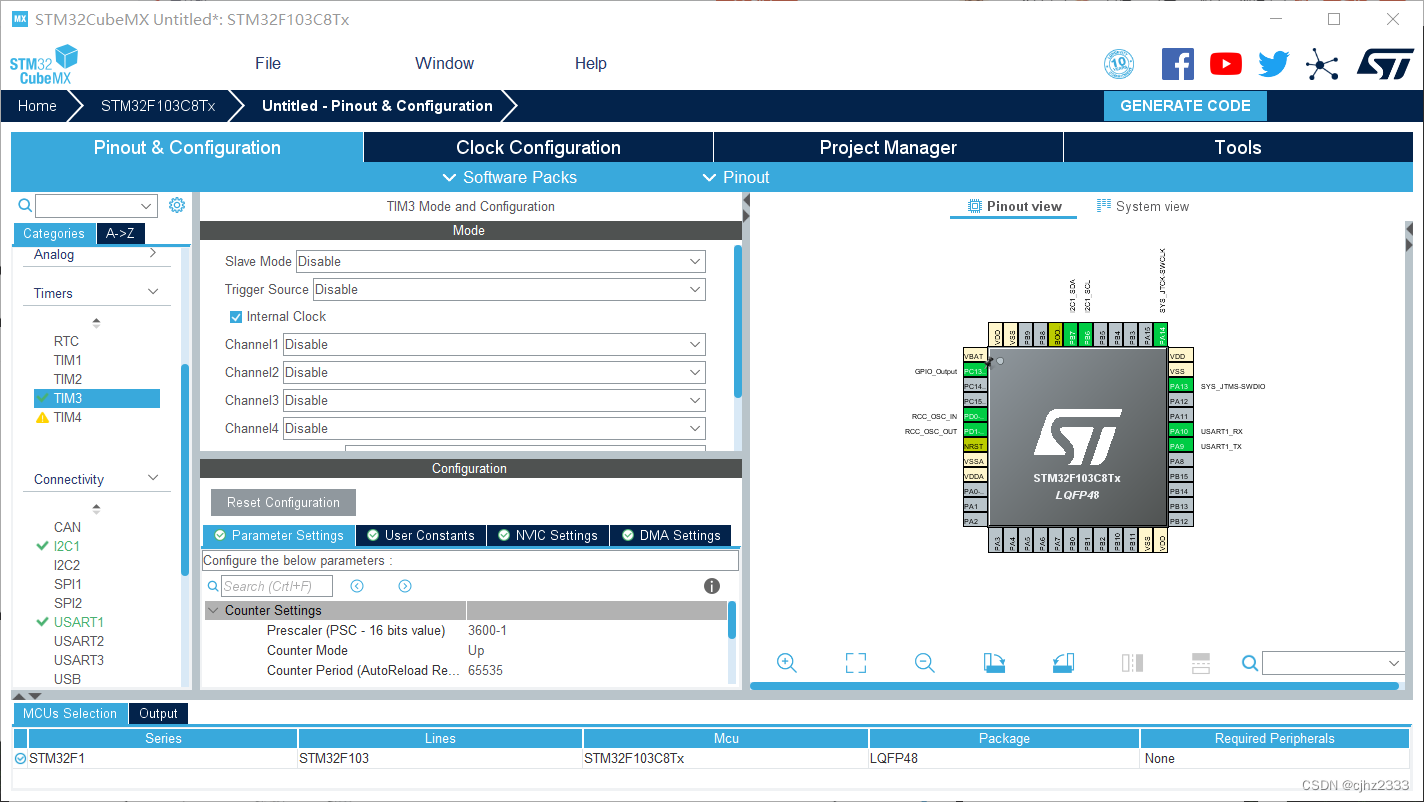
I2C:
TIM3:
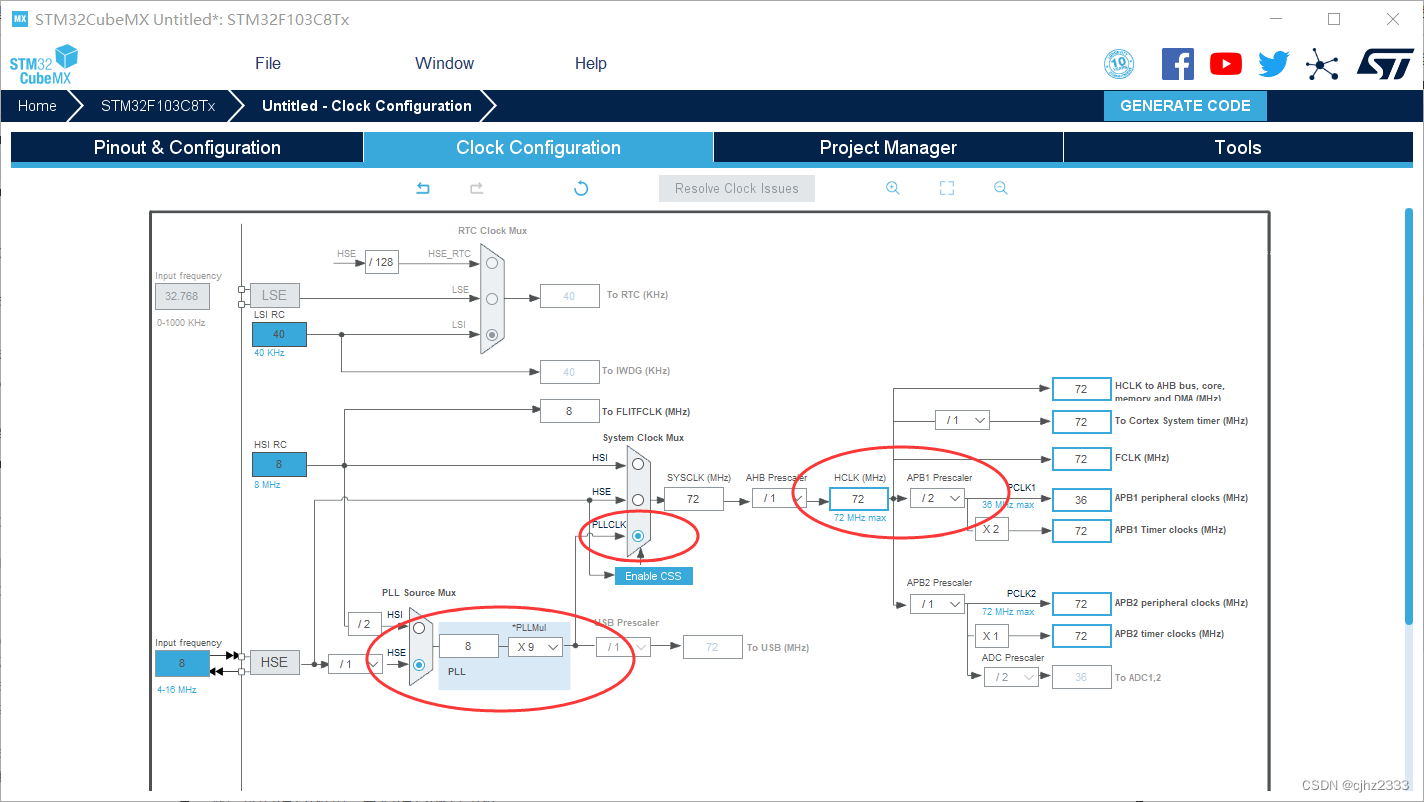
Árbol de reloj:
Luego genera el proyecto
modificación del código Keil
Primero agregue una carpeta AHT, agregue los archivos .c y .h
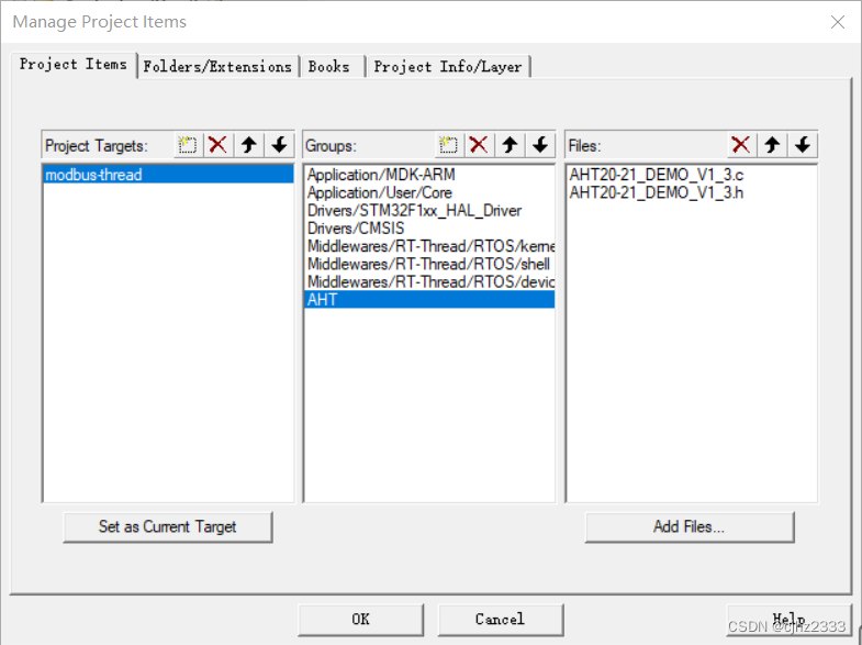
a la ruta,
luego agregue el archivo AHT.c y el archivo AHT.h
AHT.c
- /*******************************************/
/*@版权所有:广州奥松电子有限公司          */
/*@作者:温湿度传感器事业部                */
/*@版本:V1.2                              */
/*******************************************/
//#include "main.h"
#include "AHT.h"
#include "gpio.h"
#include "i2c.h"


void Delay_N10us(uint32_t t)//延时函数
{


  uint32_t k;

   while(t--)
  {


    for (k = 0; k < 2; k++);//110
  }
}

void SensorDelay_us(uint32_t t)//延时函数
{


	for(t = t-2; t>0; t--)
	{


		Delay_N10us(1);
	}
}

void Delay_4us(void)		//延时函数
{


	Delay_N10us(1);
	Delay_N10us(1);
	Delay_N10us(1);
	Delay_N10us(1);
}
void Delay_5us(void)		//延时函数
{


	Delay_N10us(1);
	Delay_N10us(1);
	Delay_N10us(1);
	Delay_N10us(1);
	Delay_N10us(1);

}

void Delay_1ms(uint32_t t)		//延时函数
{


   while(t--)
  {


    SensorDelay_us(1000);//延时1ms
  }
}


//void AHT20_Clock_Init(void)		//延时函数
//{


//	RCC_APB2PeriphClockCmd(CC_APB2Periph_GPIOB,ENABLE);
//}

void SDA_Pin_Output_High(void)   //将PB7配置为输出 , 并设置为高电平, PB7作为I2C的SDA
{


	GPIO_InitTypeDef  GPIO_InitStruct;
	GPIO_InitStruct.Mode = GPIO_MODE_OUTPUT_PP;//推挽输出
	GPIO_InitStruct.Pin = GPIO_PIN_7;
	GPIO_InitStruct.Speed = GPIO_SPEED_FREQ_HIGH;
	HAL_GPIO_Init(GPIOB,& GPIO_InitStruct);
	HAL_GPIO_WritePin(GPIOB,GPIO_PIN_7,GPIO_PIN_SET);
}

void SDA_Pin_Output_Low(void)  //将P7配置为输出  并设置为低电平
{


	GPIO_InitTypeDef  GPIO_InitStruct;
	GPIO_InitStruct.Mode = GPIO_MODE_OUTPUT_PP;//推挽输出
	GPIO_InitStruct.Pin = GPIO_PIN_7;
	GPIO_InitStruct.Speed = GPIO_SPEED_FREQ_HIGH;
	HAL_GPIO_Init(GPIOB,& GPIO_InitStruct);
	HAL_GPIO_WritePin(GPIOB,GPIO_PIN_7,GPIO_PIN_RESET);
}

void SDA_Pin_IN_FLOATING(void)  //SDA配置为浮空输入
{


	GPIO_InitTypeDef  GPIO_InitStruct;
	GPIO_InitStruct.Mode = GPIO_MODE_INPUT;//浮空
	GPIO_InitStruct.Pin = GPIO_PIN_7;
	GPIO_InitStruct.Speed = GPIO_SPEED_FREQ_HIGH;
	HAL_GPIO_Init( GPIOB,&GPIO_InitStruct);
}


void SCL_Pin_Output_High(void) //SCL输出高电平,P6作为I2C的SCL
{


	HAL_GPIO_WritePin(GPIOB,GPIO_PIN_6,GPIO_PIN_SET);
}

void SCL_Pin_Output_Low(void) //SCL输出低电平
{


	HAL_GPIO_WritePin(GPIOB,GPIO_PIN_6,GPIO_PIN_RESET);
}

void Init_I2C_Sensor_Port(void) //初始化I2C接口,输出为高电平
{


	GPIO_InitTypeDef  GPIO_InitStruct;
	GPIO_InitStruct.Mode = GPIO_MODE_OUTPUT_PP;//推挽输出
	GPIO_InitStruct.Pin = GPIO_PIN_7;
	GPIO_InitStruct.Speed = GPIO_SPEED_FREQ_HIGH;
	HAL_GPIO_Init(GPIOB,& GPIO_InitStruct);
	HAL_GPIO_WritePin(GPIOB,GPIO_PIN_7,GPIO_PIN_SET);


	GPIO_InitStruct.Mode = GPIO_MODE_OUTPUT_PP;//推挽输出
	GPIO_InitStruct.Pin = GPIO_PIN_6;
	GPIO_InitStruct.Speed = GPIO_SPEED_FREQ_HIGH;
	HAL_GPIO_Init(GPIOB,& GPIO_InitStruct);
	HAL_GPIO_WritePin(GPIOB,GPIO_PIN_6,GPIO_PIN_SET);

}
void I2C_Start(void)		 //I2C主机发送START信号
{


	SDA_Pin_Output_High();
	SensorDelay_us(8);
	SCL_Pin_Output_High();
	SensorDelay_us(8);
	SDA_Pin_Output_Low();
	SensorDelay_us(8);
	SCL_Pin_Output_Low();
	SensorDelay_us(8);
}


void AHT20_WR_Byte(uint8_t Byte) //往AHT20写一个字节
{


	uint8_t Data,N,i;
	Data=Byte;
	i = 0x80;
	for(N=0;N<8;N++)
	{


		SCL_Pin_Output_Low();
		Delay_4us();
		if(i&Data)
		{


			SDA_Pin_Output_High();
		}
		else
		{


			SDA_Pin_Output_Low();
		}

    SCL_Pin_Output_High();
		Delay_4us();
		Data <<= 1;

	}
	SCL_Pin_Output_Low();
	SensorDelay_us(8);
	SDA_Pin_IN_FLOATING();
	SensorDelay_us(8);
}


uint8_t AHT20_RD_Byte(void)//从AHT20读取一个字节
{


		uint8_t Byte,i,a;
	Byte = 0;
	SCL_Pin_Output_Low();

	SDA_Pin_IN_FLOATING();
	SensorDelay_us(8);

	for(i=0;i<8;i++)
	{


    SCL_Pin_Output_High();

		Delay_5us();
		a=0;

		//if(GPIO_ReadInputDataBit(GPIOB,GPIO_Pin_15)) a=1;
		if(HAL_GPIO_ReadPin(GPIOB,GPIO_PIN_7)) a=1;
		Byte = (Byte<<1)|a;

		//SCL_Pin_Output_Low();
		HAL_GPIO_WritePin(GPIOB,GPIO_PIN_6,GPIO_PIN_RESET);
		Delay_5us();
	}
  SDA_Pin_IN_FLOATING();
	SensorDelay_us(8);
	return Byte;
}


uint8_t Receive_ACK(void)   //看AHT20是否有回复ACK
{


	uint16_t CNT;
	CNT = 0;
	SCL_Pin_Output_Low();
	SDA_Pin_IN_FLOATING();
	SensorDelay_us(8);
	SCL_Pin_Output_High();
	SensorDelay_us(8);
	while((HAL_GPIO_ReadPin(GPIOB,GPIO_PIN_7))  && CNT < 100)
	CNT++;
	if(CNT == 100)
	{


		return 0;
	}
 	SCL_Pin_Output_Low();
	SensorDelay_us(8);
	return 1;
}

void Send_ACK(void)		  //主机回复ACK信号
{


	SCL_Pin_Output_Low();
	SensorDelay_us(8);
	SDA_Pin_Output_Low();
	SensorDelay_us(8);
	SCL_Pin_Output_High();
	SensorDelay_us(8);
	SCL_Pin_Output_Low();
	SensorDelay_us(8);
	SDA_Pin_IN_FLOATING();
	SensorDelay_us(8);
}

void Send_NOT_ACK(void)	//主机不回复ACK
{


	SCL_Pin_Output_Low();
	SensorDelay_us(8);
	SDA_Pin_Output_High();
	SensorDelay_us(8);
	SCL_Pin_Output_High();
	SensorDelay_us(8);
	SCL_Pin_Output_Low();
	SensorDelay_us(8);
    SDA_Pin_Output_Low();
	SensorDelay_us(8);
}

void Stop_I2C(void)	  //一条协议结束
{


	SDA_Pin_Output_Low();
	SensorDelay_us(8);
	SCL_Pin_Output_High();
	SensorDelay_us(8);
	SDA_Pin_Output_High();
	SensorDelay_us(8);
}

uint8_t AHT20_Read_Status(void)//读取AHT20的状态寄存器
{


	uint8_t Byte_first;
	I2C_Start();
	AHT20_WR_Byte(0x71);
	Receive_ACK();
	Byte_first = AHT20_RD_Byte();
	Send_NOT_ACK();
	Stop_I2C();
	return Byte_first;
}

uint8_t AHT20_Read_Cal_Enable(void)  //查询cal enable位有没有使能
{


	uint8_t val = 0;//ret = 0,
  val = AHT20_Read_Status();
	 if((val & 0x68)==0x08)
		 return 1;
   else  return 0;
 }

void AHT20_SendAC(void) //向AHT20发送AC命令
{


	I2C_Start();
	AHT20_WR_Byte(0x70);
	Receive_ACK();
	AHT20_WR_Byte(0xac);//0xAC采集命令
	Receive_ACK();
	AHT20_WR_Byte(0x33);
	Receive_ACK();
	AHT20_WR_Byte(0x00);
	Receive_ACK();
	Stop_I2C();

}

//CRC校验类型:CRC8/MAXIM
//多项式:X8+X5+X4+1
//Poly:0011 0001  0x31
//高位放到后面就变成 1000 1100 0x8c
//C现实代码:
uint8_t Calc_CRC8(uint8_t *message,uint8_t Num)
{


	uint8_t i;
	uint8_t byte;
	uint8_t crc=0xFF;
  for(byte=0; byte<Num; byte++)
  {


    crc^=(message[byte]);
    for(i=8;i>0;--i)
    {


      if(crc&0x80) crc=(crc<<1)^0x31;
      else crc=(crc<<1);
    }
  }
        return crc;
}

void AHT20_Read_CTdata(uint32_t *ct) //没有CRC校验,直接读取AHT20的温度和湿度数据
{


		volatile uint8_t  Byte_1th=0;
	volatile uint8_t  Byte_2th=0;
	volatile uint8_t  Byte_3th=0;
	volatile uint8_t  Byte_4th=0;
	volatile uint8_t  Byte_5th=0;
	volatile uint8_t  Byte_6th=0;
	 uint32_t RetuData = 0;
	uint16_t cnt = 0;
	AHT20_SendAC();//向AHT10发送AC命令
	Delay_1ms(80);//延时80ms左右
    cnt = 0;
	while(((AHT20_Read_Status()&0x80)==0x80))//直到状态bit[7]为0,表示为空闲状态,若为1,表示忙状态
	{


		SensorDelay_us(1508);
		if(cnt++>=100)
		{


		 break;
		 }
	}
	I2C_Start();
	AHT20_WR_Byte(0x71);
	Receive_ACK();
	Byte_1th = AHT20_RD_Byte();//状态字,查询到状态为0x98,表示为忙状态,bit[7]为1;状态为0x1C,或者0x0C,或者0x08表示为空闲状态,bit[7]为0
	Send_ACK();
	Byte_2th = AHT20_RD_Byte();//湿度
	Send_ACK();
	Byte_3th = AHT20_RD_Byte();//湿度
	Send_ACK();
	Byte_4th = AHT20_RD_Byte();//湿度/温度
	Send_ACK();
	Byte_5th = AHT20_RD_Byte();//温度
	Send_ACK();
	Byte_6th = AHT20_RD_Byte();//温度
	Send_NOT_ACK();
	Stop_I2C();

	RetuData = (RetuData|Byte_2th)<<8;
	RetuData = (RetuData|Byte_3th)<<8;
	RetuData = (RetuData|Byte_4th);
	RetuData =RetuData >>4;
	ct[0] = RetuData;//湿度
	RetuData = 0;
	RetuData = (RetuData|Byte_4th)<<8;
	RetuData = (RetuData|Byte_5th)<<8;
	RetuData = (RetuData|Byte_6th);
	RetuData = RetuData&0xfffff;
	ct[1] =RetuData; //温度

}


void AHT20_Read_CTdata_crc(uint32_t *ct) //CRC校验后,读取AHT20的温度和湿度数据
{


		volatile uint8_t  Byte_1th=0;
	volatile uint8_t  Byte_2th=0;
	volatile uint8_t  Byte_3th=0;
	volatile uint8_t  Byte_4th=0;
	volatile uint8_t  Byte_5th=0;
	volatile uint8_t  Byte_6th=0;
	volatile uint8_t  Byte_7th=0;
	 uint32_t RetuData = 0;
	 uint16_t cnt = 0;
	// uint8_t  CRCDATA=0;
	 uint8_t  CTDATA[6]={

    0};//用于CRC传递数组

	AHT20_SendAC();//向AHT10发送AC命令
	Delay_1ms(80);//延时80ms左右
    cnt = 0;
	while(((AHT20_Read_Status()&0x80)==0x80))//直到状态bit[7]为0,表示为空闲状态,若为1,表示忙状态
	{


		SensorDelay_us(1508);
		if(cnt++>=100)
		{


		 break;
		}
	}

	I2C_Start();

	AHT20_WR_Byte(0x71);
	Receive_ACK();
	CTDATA[0]=Byte_1th = AHT20_RD_Byte();//状态字,查询到状态为0x98,表示为忙状态,bit[7]为1;状态为0x1C,或者0x0C,或者0x08表示为空闲状态,bit[7]为0
	Send_ACK();
	CTDATA[1]=Byte_2th = AHT20_RD_Byte();//湿度
	Send_ACK();
	CTDATA[2]=Byte_3th = AHT20_RD_Byte();//湿度
	Send_ACK();
	CTDATA[3]=Byte_4th = AHT20_RD_Byte();//湿度/温度
	Send_ACK();
	CTDATA[4]=Byte_5th = AHT20_RD_Byte();//温度
	Send_ACK();
	CTDATA[5]=Byte_6th = AHT20_RD_Byte();//温度
	Send_ACK();
	Byte_7th = AHT20_RD_Byte();//CRC数据
	Send_NOT_ACK();                           //注意: 最后是发送NAK
	Stop_I2C();

	if(Calc_CRC8(CTDATA,6)==Byte_7th)
	{


	RetuData = (RetuData|Byte_2th)<<8;
	RetuData = (RetuData|Byte_3th)<<8;
	RetuData = (RetuData|Byte_4th);
	RetuData =RetuData >>4;
	ct[0] = RetuData;//湿度
	RetuData = 0;
	RetuData = (RetuData|Byte_4th)<<8;
	RetuData = (RetuData|Byte_5th)<<8;
	RetuData = (RetuData|Byte_6th);
	RetuData = RetuData&0xfffff;
	ct[1] =RetuData; //温度

	}
	else
	{


		ct[0]=0x00;
		ct[1]=0x00;//校验错误返回值,客户可以根据自己需要更改
	}//CRC数据
}


void AHT20_Init(void)   //初始化AHT20
{


	Init_I2C_Sensor_Port();
	I2C_Start();
	AHT20_WR_Byte(0x70);
	Receive_ACK();
	AHT20_WR_Byte(0xa8);//0xA8进入NOR工作模式
	Receive_ACK();
	AHT20_WR_Byte(0x00);
	Receive_ACK();
	AHT20_WR_Byte(0x00);
	Receive_ACK();
	Stop_I2C();

	Delay_1ms(10);//延时10ms左右

	I2C_Start();
	AHT20_WR_Byte(0x70);
	Receive_ACK();
	AHT20_WR_Byte(0xbe);//0xBE初始化命令,AHT20的初始化命令是0xBE,   AHT10的初始化命令是0xE1
	Receive_ACK();
	AHT20_WR_Byte(0x08);//相关寄存器bit[3]置1,为校准输出
	Receive_ACK();
	AHT20_WR_Byte(0x00);
	Receive_ACK();
	Stop_I2C();
	Delay_1ms(10);//延时10ms左右
}
void JH_Reset_REG(uint8_t addr)
{


	uint8_t Byte_first,Byte_second,Byte_third;
	I2C_Start();
	AHT20_WR_Byte(0x70);//原来是0x70
	Receive_ACK();
	AHT20_WR_Byte(addr);
	Receive_ACK();
	AHT20_WR_Byte(0x00);
	Receive_ACK();
	AHT20_WR_Byte(0x00);
	Receive_ACK();
	Stop_I2C();

	Delay_1ms(5);//延时5ms左右
	I2C_Start();
	AHT20_WR_Byte(0x71);//
	Receive_ACK();
	Byte_first = AHT20_RD_Byte();
	Send_ACK();
	Byte_second = AHT20_RD_Byte();
	Send_ACK();
	Byte_third = AHT20_RD_Byte();
	Send_NOT_ACK();
	Stop_I2C();

  Delay_1ms(10);//延时10ms左右
	I2C_Start();
	AHT20_WR_Byte(0x70);///
	Receive_ACK();
	AHT20_WR_Byte(0xB0|addr);//寄存器命令
	Receive_ACK();
	AHT20_WR_Byte(Byte_second);
	Receive_ACK();
	AHT20_WR_Byte(Byte_third);
	Receive_ACK();
	Stop_I2C();

	Byte_second=0x00;
	Byte_third =0x00;
}

void AHT20_Start_Init(void)
{


	JH_Reset_REG(0x1b);
	JH_Reset_REG(0x1c);
	JH_Reset_REG(0x1e);
}
AHT.h
#ifndef _AHT20_DEMO_
#define _AHT20_DEMO_

#include "main.h"

void Delay_N10us(uint32_t t);//延时函数
void SensorDelay_us(uint32_t t);//延时函数
void Delay_4us(void);		//延时函数
void Delay_5us(void);		//延时函数
void Delay_1ms(uint32_t t);
void AHT20_Clock_Init(void);		//延时函数
void SDA_Pin_Output_High(void)  ; //将PB15配置为输出 , 并设置为高电平, PB15作为I2C的SDA
void SDA_Pin_Output_Low(void);  //将P15配置为输出  并设置为低电平
void SDA_Pin_IN_FLOATING(void);  //SDA配置为浮空输入
void SCL_Pin_Output_High(void); //SCL输出高电平,P14作为I2C的SCL
void SCL_Pin_Output_Low(void); //SCL输出低电平
void Init_I2C_Sensor_Port(void); //初始化I2C接口,输出为高电平
void I2C_Start(void);		 //I2C主机发送START信号
void AHT20_WR_Byte(uint8_t Byte); //往AHT20写一个字节
uint8_t AHT20_RD_Byte(void);//从AHT20读取一个字节
uint8_t Receive_ACK(void);   //看AHT20是否有回复ACK
void Send_ACK(void)	;	  //主机回复ACK信号
void Send_NOT_ACK(void);	//主机不回复ACK
void Stop_I2C(void);	  //一条协议结束
uint8_t AHT20_Read_Status(void);//读取AHT20的状态寄存器
uint8_t AHT20_Read_Cal_Enable(void);  //查询cal enable位有没有使能
void AHT20_SendAC(void); //向AHT20发送AC命令
uint8_t Calc_CRC8(uint8_t *message,uint8_t Num);
void AHT20_Read_CTdata(uint32_t *ct); //没有CRC校验,直接读取AHT20的温度和湿度数据
void AHT20_Read_CTdata_crc(uint32_t *ct); //CRC校验后,读取AHT20的温度和湿度数据
void AHT20_Init(void);   //初始化AHT20
void JH_Reset_REG(uint8_t addr);///重置寄存器
void AHT20_Start_Init(void);///上电初始化进入正常测量状态
#endif
Transplant freeModebusRTU (HAL)
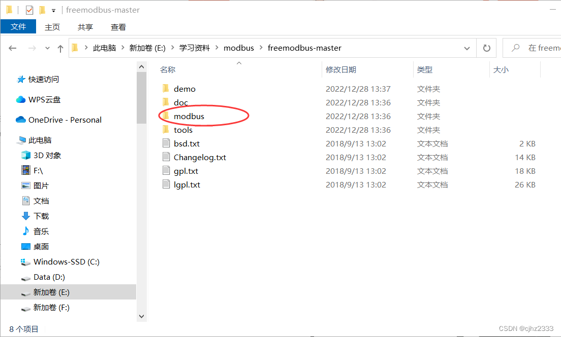
Puede descargar los archivos requeridos en https://github.com/cwalter-at/freemodbus
Abra el archivo descargado, ingrese la demostración, cree una nueva carpeta STM32MB y copie los siguientes archivos en ella,
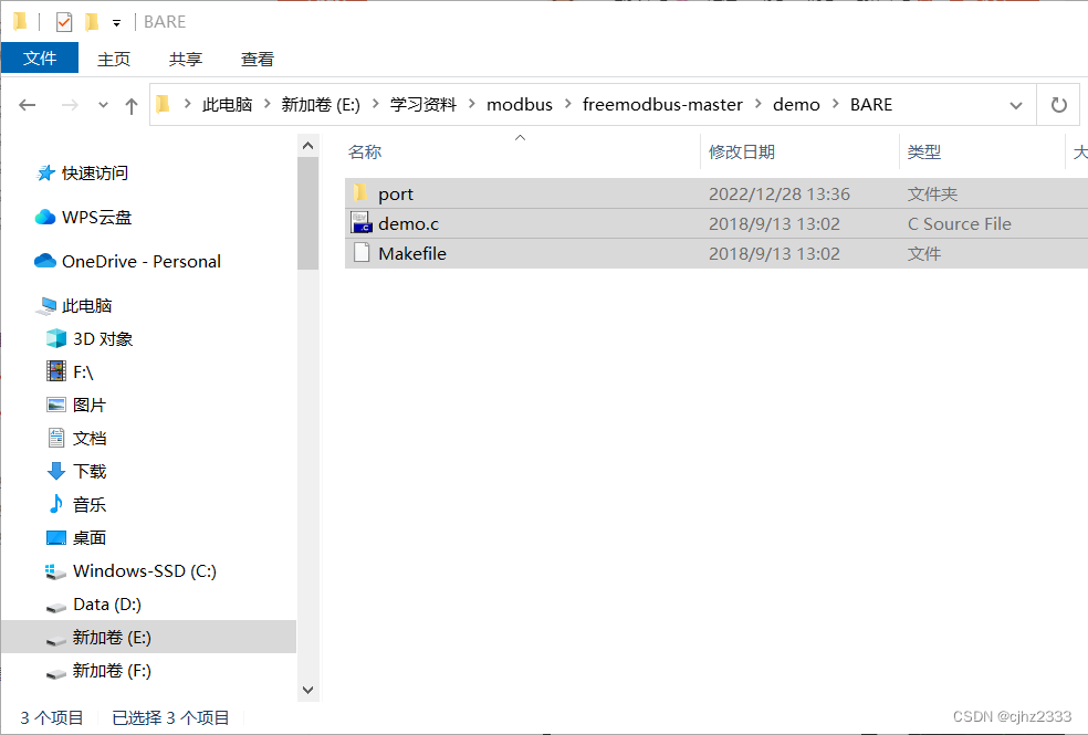
luego copie la carpeta modbus a STM32MB
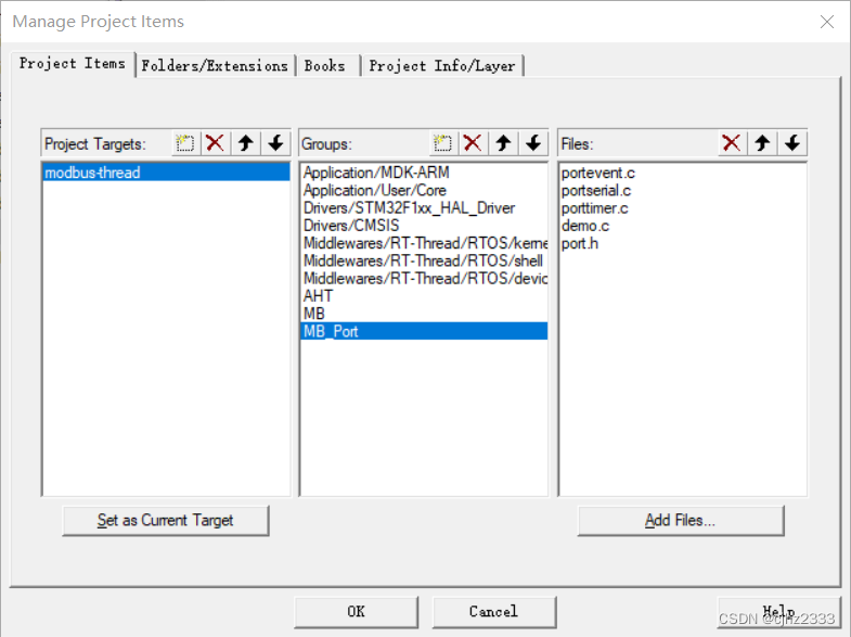
Abra el archivo MDK-ARM, copie STM32MB para
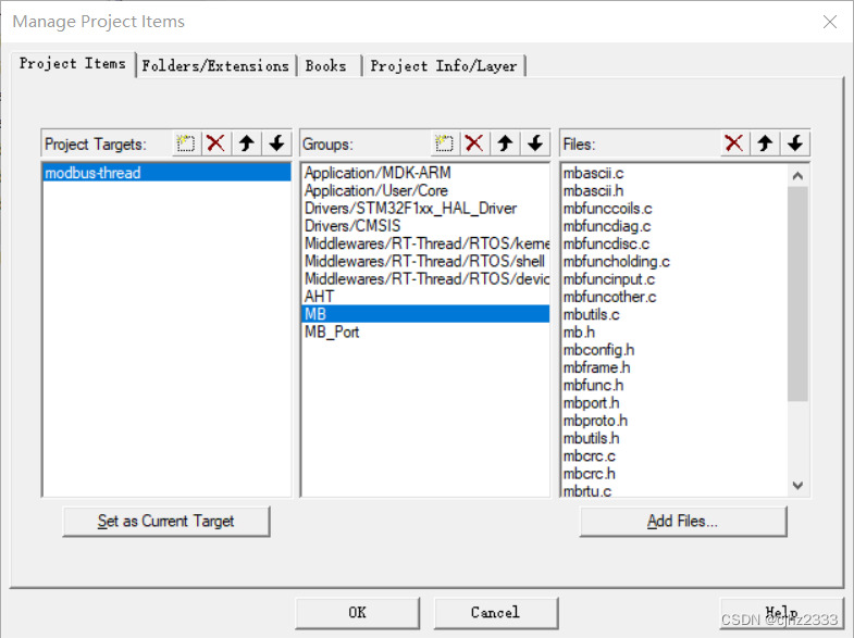
agregar archivos, cree un nuevo grupo llamado MB y MB_Port, agregue todos los archivos en la carpeta modbus debajo de la carpeta STM32MB a MB y agregue todos los .c en la carpeta del puerto debajo de la carpeta STM32MB a Archivo MB_Port y el archivo demo.c en el directorio raíz
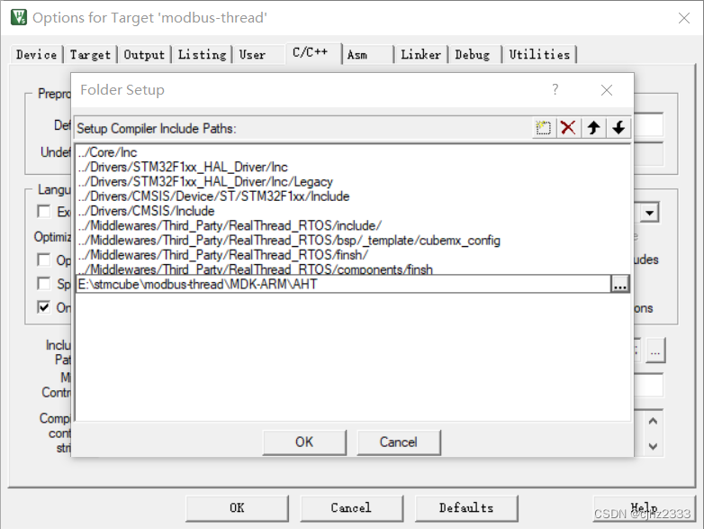
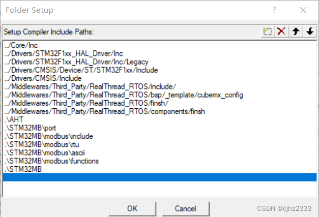
Agregue la ruta del archivo de encabezado
crear tarea
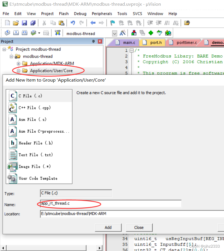
Agregue el siguiente código dentro:
#include "rtthread.h"
#include "main.h"
#include "stdio.h"
#include "usart.h"
#include "AHT20-21_DEMO_V1_3.h"
#include "mb.h"
#include "mbport.h"

struct rt_thread led1_thread;
rt_uint8_t rt_led1_thread_stack[128];
void led1_task_entry(void *parameter);


//初始化线程函数
void MX_RT_Thread_Init(void)
{


	//初始化LED1线程
	rt_thread_init(&led1_thread,"led1",led1_task_entry,RT_NULL,&rt_led1_thread_stack[0],sizeof(rt_led1_thread_stack),3,20);
	//开启线程调度
	rt_thread_startup(&led1_thread);
}

//主任务
void MX_RT_Thread_Process(void)
{


	( void )eMBPoll(  );//启动modbus侦听

}

//LED1任务
void led1_task_entry(void *parameter)
{


	while(1)
	{


		HAL_GPIO_WritePin(GPIOB,GPIO_PIN_15, GPIO_PIN_RESET);
		rt_thread_delay(500);
		HAL_GPIO_WritePin(GPIOB,GPIO_PIN_15, GPIO_PIN_SET);
		rt_thread_delay(500);
	}
}
Busque el archivo a continuación y cambie USART2 a USART1

main.c
/* USER CODE BEGIN Header */
/**
******************************************************************************
* @file : main.c
* @brief : Main program body
******************************************************************************
* @attention
*
* <h2><center>© Copyright (c) 2022 STMicroelectronics.
* All rights reserved.</center></h2>
*
* This software component is licensed by ST under Ultimate Liberty license
* SLA0044, the "License"; You may not use this file except in compliance with
* the License. You may obtain a copy of the License at:
* www.st.com/SLA0044
*
******************************************************************************
*/
/* USER CODE END Header */
/* Includes ------------------------------------------------------------------*/
#include "main.h"
#include "rtthread.h" // RT-Thread 头文件
#include "dma.h"
#include "i2c.h"
#include "tim.h"
#include "usart.h"
#include "gpio.h"
#include "mb.h"
#include "mbport.h"
#include "AHT.h"
/* Private includes ----------------------------------------------------------*/
/* USER CODE BEGIN Includes */
extern void MX_RT_Thread_Init(void); // RT-Thread 初始化函数,初始化并执行各种进程
extern void MX_RT_Thread_Process(void); // RT-Thread 主进程
/* USER CODE END Includes */
/* Private typedef -----------------------------------------------------------*/
/* USER CODE BEGIN PTD */
/* USER CODE END PTD */
/* Private define ------------------------------------------------------------*/
/* USER CODE BEGIN PD */
/* USER CODE END PD */
/* Private macro -------------------------------------------------------------*/
/* USER CODE BEGIN PM */
/* USER CODE END PM */
/* Private variables ---------------------------------------------------------*/
/* USER CODE BEGIN PV */
/* USER CODE END PV */
/* Private function prototypes -----------------------------------------------*/
void SystemClock_Config(void);
/* USER CODE BEGIN PFP */
/* USER CODE END PFP */
/* Private user code ---------------------------------------------------------*/
/* USER CODE BEGIN 0 */
/* USER CODE END 0 */
/**
* @brief The application entry point.
* @retval int
*/
int main(void)
{
/* USER CODE BEGIN 1 */
/* USER CODE END 1 */
/* MCU Configuration--------------------------------------------------------*/
/* Reset of all peripherals, Initializes the Flash interface and the Systick. */
HAL_Init();
/* USER CODE BEGIN Init */
/* USER CODE END Init */
/* Configure the system clock */
SystemClock_Config();
/* USER CODE BEGIN SysInit */
/* USER CODE END SysInit */
/* Initialize all configured peripherals */
MX_GPIO_Init();
MX_DMA_Init();
MX_I2C1_Init();
MX_TIM3_Init();
MX_USART1_UART_Init();
/* USER CODE BEGIN 2 */
AHT20_Init(); //初始化温度传感器并进行延时确保数据准确性
// HAL_Delay(2000);
eMBInit( MB_RTU, 0x01, 1, 115200, MB_PAR_NONE);//初始化modbus,走modbusRTU,从站地址为0x01,端口为1。
eMBEnable();//使能modbus
MX_RT_Thread_Init(); //初始化 RT-Thread 进程
/* USER CODE END 2 */
/* Infinite loop */
/* USER CODE BEGIN WHILE */
while (1)
{
//( void )eMBPoll( );//启动modbus侦听,由于在 RT-Thread 主进程中进行了监听启动,所以这里直接调用 RT-Thread 主进程
MX_RT_Thread_Process(); //调用主进程
/* USER CODE END WHILE */
/* USER CODE BEGIN 3 */
}
/* USER CODE END 3 */
}
/**
* @brief System Clock Configuration
* @retval None
*/
void SystemClock_Config(void)
{
RCC_OscInitTypeDef RCC_OscInitStruct = {
0};
RCC_ClkInitTypeDef RCC_ClkInitStruct = {
0};
/** Initializes the RCC Oscillators according to the specified parameters
* in the RCC_OscInitTypeDef structure.
*/
RCC_OscInitStruct.OscillatorType = RCC_OSCILLATORTYPE_HSE;
RCC_OscInitStruct.HSEState = RCC_HSE_ON;
RCC_OscInitStruct.HSEPredivValue = RCC_HSE_PREDIV_DIV1;
RCC_OscInitStruct.HSIState = RCC_HSI_ON;
RCC_OscInitStruct.PLL.PLLState = RCC_PLL_ON;
RCC_OscInitStruct.PLL.PLLSource = RCC_PLLSOURCE_HSE;
RCC_OscInitStruct.PLL.PLLMUL = RCC_PLL_MUL9;
if (HAL_RCC_OscConfig(&RCC_OscInitStruct) != HAL_OK)
{
Error_Handler();
}
/** Initializes the CPU, AHB and APB buses clocks
*/
RCC_ClkInitStruct.ClockType = RCC_CLOCKTYPE_HCLK|RCC_CLOCKTYPE_SYSCLK
|RCC_CLOCKTYPE_PCLK1|RCC_CLOCKTYPE_PCLK2;
RCC_ClkInitStruct.SYSCLKSource = RCC_SYSCLKSOURCE_PLLCLK;
RCC_ClkInitStruct.AHBCLKDivider = RCC_SYSCLK_DIV1;
RCC_ClkInitStruct.APB1CLKDivider = RCC_HCLK_DIV2;
RCC_ClkInitStruct.APB2CLKDivider = RCC_HCLK_DIV1;
if (HAL_RCC_ClockConfig(&RCC_ClkInitStruct, FLASH_LATENCY_2) != HAL_OK)
{
Error_Handler();
}
}
/* USER CODE BEGIN 4 */
/* USER CODE END 4 */
/**
* @brief This function is executed in case of error occurrence.
* @retval None
*/
void Error_Handler(void)
{
/* USER CODE BEGIN Error_Handler_Debug */
/* User can add his own implementation to report the HAL error return state */
__disable_irq();
while (1)
{
}
/* USER CODE END Error_Handler_Debug */
}
#ifdef USE_FULL_ASSERT
/**
* @brief Reports the name of the source file and the source line number
* where the assert_param error has occurred.
* @param file: pointer to the source file name
* @param line: assert_param error line source number
* @retval None
*/
void assert_failed(uint8_t *file, uint32_t line)
{
/* USER CODE BEGIN 6 */
/* User can add his own implementation to report the file name and line number,
ex: printf("Wrong parameters value: file %s on line %d\r\n", file, line) */
/* USER CODE END 6 */
}
#endif /* USE_FULL_ASSERT */
/************************ (C) COPYRIGHT STMicroelectronics *****END OF FILE****/
compilar y quemar
resultado
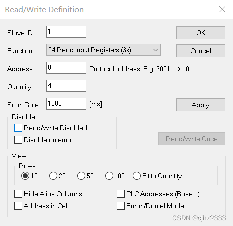
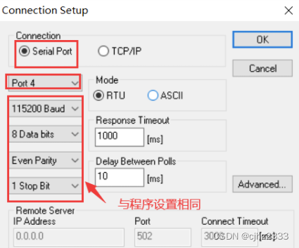
Abra modbuspoll, haga clic en Configuración y configúrelo como se muestra en la siguiente figura.
Configure la
luz de conexión PC13 para que parpadee,

Referencias
https://blog.csdn.net/weixin_46129506/article/details/121914039
https://blog.csdn.net/qq_47281915/article/details/122328414
https://blog.csdn.net/weixin_54435584/article/details/ 128449883?spm=1001.2014.3001.5502