1. SDN related concepts
1. Large Layer 2 network
In the Internet era, user access is called north-south traffic, while data transmission between data centers is called east-west traffic.
In many cases, data access and data synchronization between different data centers are required. And to synchronize these traffic requires certain challenges to this security and stability. The technology that makes these data center networks into a seemingly large logical Layer 2 network is called virtual network technology. This logically large network is a Layer 2 network. Currently, large Layer 2 networks exist in the virtualization of data centers. Direction related, cloud computing and other major network technologies.
The realization of different data communication relies on vlan to communicate directly, so the essence of layer 2 communication is to tunnel, and let the data follow the tunnel for forwarding, which is somewhat similar to mpls (tunnel forwarding), but between establishing tunnels, the routing of these data centers is required. Reachable, in the case of ensuring that the three layers can communicate with each other, a tunnel is established to provide high-speed and secure data access.
There are really many types of mpls, including MPLS L2VPN, MPLS L3VPN, LDP, mlps 6vpn/6pe, and mpls TE. They all have one thing in common, relying on the LDP protocol (label distribution). This LDP is also a major protocol of Mpls.
- mlps 6vpn/6pe: a transitional technology that allows scattered ipv6 networks to pass through ipv4 tunnels to access the ipv6 network at the other end
- mpls l2vpn: It can provide a point-to-point or point-to-multipoint service, and forward user packets according to the mac of the private network, (two-layer vpn)
- mpls l3vpn: This is a relatively classic three-tier VPN technology, based on pe-based three-tier VPN technology (pe: the router at both ends of the lsp, the earliest router device that provides label switching)
- mpls Te: This is the traffic engineering of mpls, which enables high-priority traffic to occupy low-priority LSP bandwidth.
2. SDN related terms
The following are terms related to SDN technology.
- Software-Defined Networking (SDN): Software-Defined Networking (SDN) can build an open and programmable network environment, which realizes centralized control and management of the network on the basis of virtualizing various underlying network resources.
- Software-Defined Local Area Network (SD-LAN): Local area network based on software-defined networking, which can create a flexible and cost-effective wireless and wired access network.
- Software-defined wide-area network (SD-WAN): a wide-area network based on software-defined networks, which is often used to connect enterprises with large regional spans and their data centers.
- OpenFlow: OpenFlow is a protocol for configuring flows, flowtables, and TCAMs.
- OpenDaylight: OpenDaylight is an open standard controller dominated by the Linux platform.
- OpenStack: OpenStack is an open source cloud operating system used to create and manage cloud resources.
- CloudStack: CloudStack is an open source cloud computing software used to create, manage and deploy cloud service infrastructure.
- Orchestration: Orchestration is a system that automatically creates, initializes, coordinates, and manages the physical and virtual resources required for cloud service delivery.
- OSS: OSS is a short-term operation and maintenance support system that can help service operators monitor, analyze and manage telephone or computer networks.
- SDN Controller: An SDN Controller is an application in Software Defined Networking (SDN) that is responsible for traffic control to ensure an intelligent network. It's based on protocols like OpenFlow that allow servers to tell switches where to send packets.
- White box switch: also known as an openflow switch, is a consumer switch hardware pre-installed with a third-party network operating system.
- NFV (Network Functions Virtualization Network Function Virtualization): A concept for network architecture, using virtualization technology to divide the functions of the network node level into several functional blocks, which are implemented in software, and are no longer limited to hardware architecture.
3. SDN-related protocols
As a new technology, the following is the relevant agreement content of SDN technology.

Data center: bgp evpn vxlan, vxlan
sdn technology: pcep, bgp-ls, OpenFlow, ovsdb, SR/SRv6, netconf, bgp flowspec
The most common protocol for SDN is OpenFlow, but in addition to OpenFlow, the following protocols can also be used for SDN.
- OpenFlow protocol: OpenFlow is the first-generation standard protocol for software-defined networking (SDN), which defines an open protocol that enables SDN controllers to interact with forwarding platforms of network devices.
- NETCONF protocol: Defined by RFC 6241, it is used to replace command line interface (CLI, command line interface), Simple Network Management Protocol (SNMP, Simple Network Management Protocol) and other proprietary configuration mechanisms. The management software can use the NETCONF protocol to write configuration data to the device and retrieve data from the device.
- OF-Config protocol: The OF-Config protocol is a protocol for configuring OpenFlow switches. Its main functions include configuration of multiple controllers connected to the switch, configuration and allocation of resources such as ports and queues, and status modification of resources such as ports. .
- XMPP protocol: XMPP is a protocol based on XML, a subset of the standard general markup language, which inherits the flexible development in the XML environment.
- OpFlex protocol: It is an alternative to the OpenFlow protocol introduced by Cisco (Cisco). The OpFlex protocol is designed to preserve network infrastructure hardware as the fundamental control element of a programmable network.
The principles of SR and SRV6 are different. One is label forwarding and igp protocol extension, and the other is the use of the ipv6 header extension field & use the SRH information in this field for forwarding.
Vxlan is classified into the application of the data center. It is used for tunneling and has a certain relationship with SDN. The other eight are classified as protocols with SDN attributes. SDN is to allow the network to have the ability to program, to adjust network resources more dynamically through programs, and to allocate network resources. This is the mainstream trend in the 21st century.
Among them, openflow and ovsdb mainly work on the PCC (computer controller, the brain responsible for computing programming). The main function is that the controller communicates with multiple switches, allowing the switch to receive the lsp information of the controller, so that the switch Multiple different tunnels are formed. Data is then quickly forwarded through these tunnels. To improve network quality and capacity, the purpose of SR and SRv6 is also to achieve the same goal.
2. Overview of SDN
1. Background of SDN
A disadvantage of the current routing protocol is that the main routing algorithm is very small, and most of them are used to maintain the topology and neighbor relationship, such as RIP, OSPF, IS-IS, etc., this point is defined by the distribution system, in order to solve this problem , So there is SDN.
Software-defined networking (SDN) provides high programmability, making network expansion, system design and management easier. That is to say, SDN actually integrates the same part of different protocols, that is, the distrilbuted system, into Network OS, and the routing algorithm becomes an APP. Therefore, the routing protocol has not disappeared, but has become another form.

SDN is a new type of network structure with logically centralized control. Its main feature is the separation of the data plane and the control plane, and the information exchange between the data plane and the control plane is realized through the standard open interface OpenFlow.
SDN has absorbed the experience of the evolution of the computing model from a closed, integrated, dedicated system to an open system. By separating the data plane and the control plane in the traditional closed network equipment, the network hardware and the control software are separated, and an open standard interface is formulated. Allows network software developers and network administrators to control the network through programming, turning traditional dedicated network devices into standardized general-purpose network devices that can be defined through programming.
SDN can implement all protocols, and can also abandon all protocols, because SDN is not at the same level as control protocols.
The problem that SDN solves is to separate the implementation of the protocol from the hardware layer, describe the hardware with a unified model, and turn the parts other than the unified model into flow tables and controllers. Arbitrary network protocols can be implemented through flow tables and controllers, including traditional control protocols. Upgrading the controller allows the SDN network to support more protocols.
Rationally speaking, no matter how developed SDN is, it is impossible to control the entire Internet with one controller. Routing and switching protocols are the foundation of the modern Internet, so whether it is a network implemented by SDN or a traditional network, routing and switching protocols will still be unavoidable in the foreseeable future.
2. Abstract structure of SDN network
The network abstract structure of SDN consists of four abstract models: control plane abstract model, forwarding plane, management plane, and operation plane.
The interface between the control plane and the data plane, and the interface between the control plane and the application plane are called the south bound interface and the north bound interface, respectively, and the interfaces between the SDN controllers inside the control plane are called the east bound interface and the north bound interface. Westbound interface.
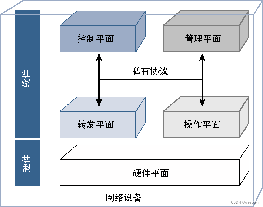
The software used by traditional network devices to implement network functions usually includes multiple roles. We can classify these roles into functional planes that work independently. These functional planes interact through proprietary or open APIs (Application Program Interface, application programming interface) . From a high-level perspective, these roles can be divided into the following four categories.
- Control plane: The main function is to determine the path of data flowing through the device, decide whether to allow data to penetrate the device, the queuing behavior of data, and various operations required by the data, etc. This role is called the control plane.
- Forwarding plane: The function of this part of software is to forward, queue and process data on the device according to the instructions of the control plane. This role is called the forwarding plane or data plane. Thus, the control plane's responsibility is to determine what to do with the data coming into the device, while the data plane's responsibility is to perform specific actions based on the control plane's decisions.
- Management plane: The control plane and forwarding plane are responsible for processing data traffic, while the management plane is responsible for network device configuration, fault monitoring and resource management.
- Operation plane: The operating status of equipment is monitored by the operation plane, which can directly view all equipment entities. The management plane directly cooperates with the operation plane, and uses the operation plane to retrieve the health status information of the device, and is also responsible for pushing configuration updates to manage the running status of the device.
For traditional network equipment, these planes are fully coupled together and communicate through proprietary interfaces and protocols, as shown in the figure below.
The SDN control plane abstract model supports users to control the network through programming on the control plane without caring about the details of the data plane implementation. Through statistical analysis of network status information, an abstract model of a global and real-time network status view is provided. The network control plane can prioritize routes according to the global network status, improve the security of the network system, and enable the network to have stronger management and control capabilities. and security.
To better explain these concepts, let's take a router as an example. The management plane responsible for router configuration provides a mechanism to define parameters such as hostname, interface IP address to use, routing protocol configuration, thresholds and classifications for QoS (Quality of Service), and the operation plane is responsible for Monitor interface status, CPU consumption, memory utilization, etc., and transmit the status information of these resources to the management plane for fault monitoring. The routing protocol (defined by the management plane) running on the router constitutes the control plane, which can predetermine the data flow to build a routing lookup table (called RIB [Routing Information Base, routing information base]), and map this data to the router's specific outgoing interface. The forwarding plane then uses this routing lookup table and determines the path for data to traverse the router.
Because the control plane is integrated in the device software, the network architecture has a distributed control plane, each node will perform its own control plane computing operations, and these control planes can exchange information with each other. For example, routing protocols running on each device exchange information to determine the topology of the entire network or learn routing information from each other. Although the management plane is also localized accordingly, NMS (Network Management System, Network Management System) adds a layer of management layer on the management plane, thus realizing the centralization of management functions.
Usually, protocols such as Syslog, SNMP (Simple Network Management Protocol, Simple Network Management Protocol) and NetFlow are used to perform monitoring operations, while configuration operations are completed using proprietary CLI, API, SNMP or scripts.
The following figure shows a schematic diagram of the deployment architecture of traditional network devices:

Programmability is at the heart of SDN. Programmers can write programs to control various network devices (such as routers, switches, gateways, firewalls, servers, wireless base stations) as long as they master the programming method of the network controller API, without knowing the specific configuration commands of various network devices. syntax, semantics. The controller is responsible for converting API programs into instructions to control various network devices. New network applications can also be easily added to the network through API programs. An open SDN architecture makes the network universal, flexible, secure, and supports innovation.
3. Introduction to SDN
SDN is not a protocol, but an open network architecture.
SDN is a structure that changes the traditional tightly coupled data plane and control plane into a structure that decouples and separates the data plane and control plane, and centralizes the network control plane functions of routers to the SDN controller. SDN routers are programmable switches. The SDN controller realizes the control of router data plane functions by issuing routing information and control commands.
SDN centrally controls network logic through standard protocols, realizes flexible control and management of network traffic, and provides a good platform for core network and application innovation.
In an SDN network, SDN is not intended to replace the control plane of routers and switches, but to strengthen the control plane with a view of the entire network, and determine the routing and grouping of each node according to dynamic traffic, delay, quality of service and security status Forwarding strategy, and then push the control command to the control plane of the router and the switch, and the control plane controls the packet forwarding process of the data plane.
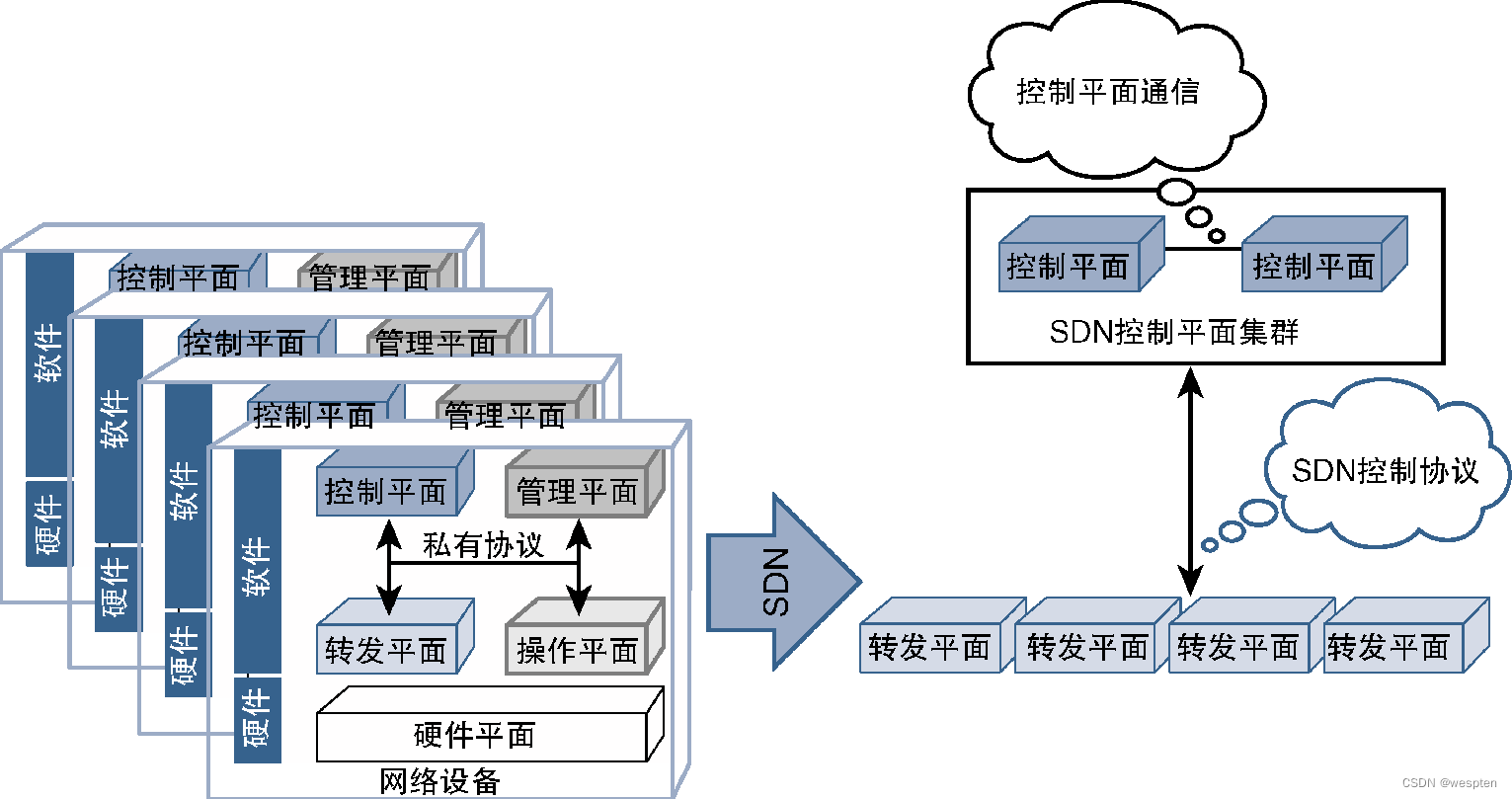
Although the goal of SDN is to separate the control plane from the forwarding plane, it is not mandatory to limit the centralized control plane to a single node. In order to achieve scalability and high availability, the control plane is allowed to be extended horizontally to form a control plane cluster. The modules containing the cluster function can pass BGP (Border Gateway Protocol, Border Gateway Protocol) or PCEP (Path Computational Element Communication Protocol, path Computing unit communication protocol) and other protocols to communicate to achieve a single centralized control plane.
The following figure shows the basic concept of SDN and the differences with the traditional network architecture. It should be noted that since the focus of SDN is the control plane and forwarding plane, the figure does not emphasize the relationship between these planes and the hardware plane or operation plane and Interaction issues between management planes.
In the implementation of SDN, the control plane can be managed through the application program. The application program can interact with the control plane and the management plane, extract device information and device configuration from the management plane, and extract network topology and traffic path information from the control plane. Therefore, the application The program has a complete and unified view of the network and uses this information to make processing decisions that can be passed to the control plane or management plane, as shown in the figure below.

The figure also shows the concepts of northbound and southbound protocols and APIs. The meanings of these terms are related to the environment in which they are used. The figure shows the application scenarios of SDN control plane and management plane. At this time, the southbound protocol refers to It is the communication from the control plane or management plane to the bottom plane. The interface provided by the management plane and the control plane to the upper plane (such as the application layer) is called northbound API or northbound protocol.
A typical example of this type of application is on-demand bandwidth. Applications can monitor traffic in the network and provide additional traffic paths during certain hours of the day or when predetermined thresholds are exceeded. The management plane must provide applications with information about network interfaces. The control plane provides real-time forwarding topology, and applications use this information to determine whether additional traffic paths need to be provided for specific traffic. User-defined policies can be used to preset thresholds for the application that trigger the appropriate action, which the application communicates by instructing the management plane to provide a new traffic path and telling the control plane to start using that traffic path.
4. Advantages of SDN
When SDN was first introduced, its benefits were not strong enough for vendors or service providers to firmly move in this direction. At that time, the network expansion deployment plan still adopted a partially automated configuration and management mechanism, and the tightly coupled method of the control plane and the data plane did not become a major bottleneck for network expansion. technology.
Later, the network gradually faced the demand for exponential scale growth, which caused a large number of limiting factors in the expansion mechanism of the traditional network. NFV is one success story of the networking industry pioneering innovation and adopting new technologies to break free from vendor lock-in, and SDN is another. From academia to real-world application deployment, SDN did not take too much time. Since SDN can realize a flexible, scalable, open and programmable network, it has been deployed more and more widely.
Some of the important advantages of SDN are discussed in detail below, all of which are closely related to reducing the cost of network operation.
1. Programmability and automation
The ability to control the network through applications is an important advantage of SDN. The current network needs to have stronger network recovery capabilities, large-scale scalability, faster deployment mechanisms, and the ability to optimize operating costs. However, due to manual processing The process cannot provide a fast processing mechanism, so the operation of the entire network has to slow down, and the maximum use of automation tools and applications has become a must to meet the needs of the network. Automation and programmability are required to support the on-demand configuration of the network , Monitoring and analysis of device data, but also need to make real-time changes according to traffic load conditions, network interruptions, and known and unknown events that occur in the network. In the traditional sense, the solutions provided by manufacturers are mainly for their own devices or OS (Operating System, operating system), and sometimes provide limited support for external devices (if any), according to the logic and constraints to make decisions.
SDN solutions couple applications to the network, solving the problems of manual control and management processes. Since SDN puts intelligence on a centralized control device (that is, the SDN controller), programs and scripts that automatically respond to expected and unexpected events can be built directly in the controller. As an option, the application can also run on the controller, and use the northbound API to transfer the logic to the controller and finally to the forwarding device. Applications can handle failures and increasingly management needs, enabling rapid resolution and recovery from failures. This approach minimizes operational costs by significantly reducing service downtime, shortening configuration time, and increasing the ratio of equipment to network operations personnel.
2. Support centralized control
After the control plane is centralized, all important information can be obtained more easily, and the implementation of the control logic is also relatively simple. SDN can unify network views, simplify network control logic, and reduce operational complexity and maintenance costs.
3. Multi-vendor and open architecture
Because SDN uses standardized protocols, it breaks the dependency on vendor-specific control mechanisms. Device access and device configuration methods provided by traditional vendors are proprietary methods, not easy to program, and there are many obstacles in developing applications and scripts to automate some configuration and management processes, especially in the hybrid vendor ( Even in a mixed OS) environment, applications must account for changes and differences in device interfaces. Furthermore, if there are differences (possibly parsing differences) in how vendors implement standard control plane protocols, then this can lead to interoperability issues. These challenges have long existed in traditional networks, but SDN frees up the control plane of devices, leaving only the data plane, thus potentially solving the problem of control plane interoperability in mixed-vendor deployment environments.
4. Simplify network equipment
The control plane of network devices usually takes up a lot of network resources (especially network devices running multiple protocols), and transfers various information (such as internal routes, external routes and labels, etc.) between these protocols, and then stores them locally This information, while also running other protocol logic to leverage the data for path computation, all of these operations impose unnecessary overhead on the device and limit its scalability and performance. Since SDN strips these overheads from the equipment, allowing the network equipment to focus on the main responsibility (forwarding data), the processing resources and memory resources of the equipment are released, thus greatly reducing the equipment cost, simplifying the software implementation, and thus obtaining more benefits. Good scalability to achieve the best utilization of equipment resources.
3. Principles of SDN Implementation
As mentioned earlier, the core idea of SDN is to separate the control plane and separate the control plane from the forwarding plane. A straightforward way to achieve this goal is to implement the control plane functionality on an external device (called an SDN controller), leaving the forwarding plane functionality on the device in the data path.
However, as you learn more and more about the concept of SDN, you will find that there are many ways to achieve the basic goals of centralizing control and simplifying the data plane.
1. Introduction to SDN Controller
The SDN controller is an independent device that realizes the function of the SDN control plane, and is responsible for transmitting the decision information of the control plane to the network device. At the same time, the SDN controller can also retrieve information from network devices to make sound control plane decisions. The SDN controller communicates with network devices through the SDN control protocol.
From the perspective of geographical location, SDN controllers do not need to be deployed in the same geographical location as network devices, as long as they can communicate with the network devices they control. At present, the industry provides a variety of open source and commercial SDN controllers, and the relevant content of these SDN controllers will be discussed in detail later.
2. SDN implementation model
From a technical point of view, it is not always feasible for vendors to completely separate the control plane of the network equipment and let the network equipment perform pure forwarding functions. Therefore, vendors have adopted different methods to implement SDN, which is different from the SDN implementation we have discussed so far. Mechanisms are not completely consistent. Service providers also face many practical difficulties, and it is difficult to completely migrate their networks to SDN, so it is possible to adopt some alternative solution to deploy SDN, as long as these alternative implementation solutions can fully enjoy the benefits brought by SDN, they can Realizing the separation of the control plane and the forwarding plane is an effective way to implement SDN.
Common SDN implementation methods mainly include the following three types.
1. Open (Classic) SDN
This method is a classic implementation way to realize the separation of the control plane and the forwarding plane. Since the network equipment developed by the supplier is temporarily unable to achieve this goal, this method uses the SDN Support Layer (SDN Support Layer) to replace the local control plane to realize the SDN support capability.
The new SDN support layer can work with the SDN controller and the forwarding plane of the device, so that the network device has the ability to communicate with the SDN controller through the SDN protocol, and can directly control the forwarding plane, as shown in the following figure.

2. Hybrid SDN
Many vendors have adopted SDN implementations that modify the control plane of devices through the SDN support layer, and claim that their devices are already SDN-enabled. But this does not mean that the local control plane of the device no longer exists, local intelligence can still work with the control plane implemented by the external controller.
For this implementation, because the device will run its own (distributed) local control plane, and the external SDN controller will enhance the intelligence of the device by modifying the routing parameters used by these protocols or directly modifying the forwarding plane, so the The implementation method is called hybrid SDN, as shown in the figure below.

Note that the main difference in a hybrid SDN implementation compared to a classic SDN implementation is that the device still uses a local control plane.
3. Realize SDN through API
Some vendors implement SDN by providing APIs for deploying, configuring, and managing devices. Applications can control the forwarding plane of the device through the API, which is equivalent to the southbound API used between the controller and the network device. However, since the API can be plugged directly into the application, such an SDN implementation may not require an SDN controller using standard southbound protocols.
Compared with the private CLI (Command-Line Interface, command-line interface) that suppliers have been using, this implementation is to change to a more collaborative and open direction, but it is difficult to achieve true openness, because these APIs It is likely that multi-vendor compatibility will not be achieved, thus not really addressing the privacy issue. Applications using this API-based implementation of SDN must know which vendor's equipment they are communicating with in order to be able to use the correct API.
The argument in favor of this approach to SDN is that it allows applications to influence forwarding decisions, and that APIs are publicly available to anyone who wants to build applications and consume them, thus achieving the core goals of SDN. While this approach allows network programmability, it lacks flexibility (due to private southbound APIs). Some vendors address the flexibility issue by offering their own controllers that use a private southbound API (for network devices) and a standard northbound API.
The following figure shows the implementation of SDN through API:

4. Realize SDN through overlay
Another way to separate the control plane from the network is to create a separate overlay network on top of the existing network, where the underlying network still has the control plane managed locally in the traditional way. However, for an overlay network, the underlying network essentially just provides connectivity and forwards data.
For network users, the underlying network and its topology and control plane are transparent, and the overlay network is the network that interacts with users. Users in this implementation mode can manage the overlay network through an external controller, and do not need the devices constituting the underlying network to support any SDN functions. The implementation of the SDN network meets the basic requirements of SDN, and the only constraint is that the underlying equipment must support the protocol for implementing the overlay network. The concept of a virtual network was discussed above, and a virtual network is actually an overlay network.
Technical solutions using this SDN implementation mainly include VXLAN (Virtual Extensible LAN) supported by a large number of suppliers and NVGRE (Network Virtualization using Generic Routing Encapsulation) supported by Microsoft. .
3. SDN protocol content
Regardless of the method used to implement SDN, some type of protocol must be used to complete the communication and information exchange between forwarding devices, applications, and controllers. From the perspective of the SDN controller, these protocols can be divided into northbound protocols and southbound protocols. As mentioned above, the southbound protocol is used for communication between control plane devices (such as SDN controllers or applications) and the forwarding plane, while the northbound protocol is used for communication between applications and SDN controllers.
1. Southbound Agreement
Southbound protocols can be divided into two categories. One is that the control plane can directly communicate with the forwarding plane, and the other is that the control plane indirectly affects the forwarding plane by changing device parameters through the management plane. Protocols that directly interact with the forwarding plane are called SDN control plane protocols, and protocols that use the management plane to change the forwarding plane are simply called management plane protocols.
The following figure shows the schematic diagram of SDN protocol classification:

2. SDN control plane protocol
The SDN control plane protocol operates on the network device as a low-level protocol, and the device hardware can be programmed to directly control the data plane. Common SDN control plane protocols mainly include OpenFlow, PCEP (Path Computation Element Communication Protocol, Path Computation Element Communication Protocol), and BGP Flow-Spec.
A brief analysis of these agreements will be made below.
1)OpenFlow
The communication process between the control plane and the forwarding plane of the traditional network equipment provided by the equipment manufacturer takes place in the same equipment, and these equipment use proprietary communication protocols and internal process calls. For the SDN environment, since the control plane and the forwarding plane are separated, a standard protocol supporting multiple suppliers is required to complete the communication process between them. Therefore, OpenFlow came into being. OpenFlow is the industry's first open source control protocol for communication between SDN controllers and network devices and programming the forwarding plane.
OpenFlow has gradually matured from the initial laboratory version, and currently provides product-level software of version 1.3 and above.
OpenFlow is responsible for maintaining information called a flow table on the device, which contains information about how to forward data. The SDN controller can program the forwarding plane of the OpenFlow-supporting switch through the OpenFlow protocol by changing the flow table on the device.
To program forwarding information and set paths in the network, OpenFlow supports two modes of operation, passive and active. The passive mode is the default operation mode for implementing SDN by using OpenFlow, assuming that the network device has no intelligence or does not run related functions of the control plane.
In passive mode, the first packet of data traffic received by all forwarding nodes is sent to the SDN controller, which uses this information to program the data flow traversing the entire network. Create flow tables in all subsequent devices and switch data traffic accordingly. In active mode, the SDN controller will pre-configure some default flow values, and after the switch starts up, the traffic flow will be pre-programmed.
When the SDN controller and the switch exchange information flows through the network, it is recommended to perform OpenFlow communication through a secure channel, such as SSL (Secure Socket Layer, Secure Socket Layer) or TLS (Transport Layer Security, Transport Layer Security).
The following figure shows the architecture of OpenFlow:

OpenFlow mainly focuses on the relationship between the control plane and the data plane, but if the management plane and operation plane of the device must still be managed in the traditional way, then the programmability advantages that OpenFlow brings to SDN will be weakened. The original OpenFlow was developed for switches, with less consideration for management functions. In order to obtain the full benefits of programmability, it is required that the management plane should also have interfaces that can be used by applications.
Therefore, two different protocols can be used to improve the management and configuration capabilities of OpenFlow: OF-CONFIG (OpenFlow Configuration, OpenFlow configuration) management protocol and OVSDB (Open vSwitch Database, open virtual switch database) management protocol.
2)PCEP
PCEP (Path Computation Element Communication Protocol, Path Computation Element Communication Protocol) is a protocol that works between two devices, one of which uses TE (Traffic Engineering, Traffic Engineering) for forwarding, and the other device is responsible for execution All calculations required to determine traffic engineering paths. PCEP is defined by RFC 4655, which defines the device running the TE protocol as PCC (Path Computation Client, Path Computation Client), and defines the device that performs all computing functions as PCE (Path Computation Element, Path Computation Unit), PCE and The agreement between PCC is called PCEP.
PCC can be any traditional routing device that has enabled the ability to work with PCE. In the traditional sense, routers perform their own computing operations and exchange information with each other, while routers in the PCEP model (acting as PCC) perform traffic forwarding and labeling. Operations such as addition and processing leave all calculation and path decision-making processes to the PCE. If there are multiple PCEs working together, PCEP can also be used as a communication protocol between these PCEs. If you want to learn LSDB (Link State Data Base, link state database) information from the network, then you can establish a passive IGP relationship between the PCE device and the device in the network, but because doing so will limit the PCE's cognition of the network area boundary, Therefore, an alternative solution called BGP LS (BGP Link State, BGP Link State) is proposed. BGP LS is a new BGP extension protocol that can provide LSDB information to PCE.
Since the design of PCEP is based on the traffic engineering use case of SDN, protocols such as RSVP-TE, GMPLS (Generalized MPLS, Generalized MPLS)-based TE, and SR-TE (Segment Routing TE, Segment Routing TE) are adopted. In these scenarios, The roles of PCEP, PCC and PCE are the same.
For example, the PCC can request the PCE to perform path computation operations under certain constraints, and the PCE can return possible paths satisfying the constraints.
3)BGP-FS
BGP-FS (BGP Flow Spec, BGP flow specification) is a supplementary protocol of the BGP protocol, which defines the method for BGP routers to advertise flow filtering rules to upstream BGP peer routers. Specific actions to take on matched traffic (including dropping those matched traffic).
BGP-FS is a standard protocol defined in RFC 5575 and supported by a large number of vendors. BGP-FS defines a new BGP NLRI (Network Layer Reachability Information, network layer reachability information), which can be used to create flow specifications. Essentially, a flow specification is a matching condition, such as source address, destination port, QoS value, and packet length. For matching traffic, the system can perform operations such as rate limiting, QoS classification, discarding, and redirection to a VRF (Virtual Routing and Forwarding, virtual routing and forwarding) instance.
For SDN scenarios, the SDN controller can establish a BGP neighbor relationship with the forwarding device. As long as all devices support BGP-FS, the controller can send traffic filtering rules to these devices through BGP-FS to control the forwarding behavior. . In fact, the original purpose of BGP-FS is to redirect or drop DDoS (Distributed Denial of Service) attack traffic. In this scenario, the controller (after detecting the attack) instructs the router facing the attack traffic to drop the matching traffic. Or divert this traffic to a traffic scrubbing device.
3. SDN management plane protocol
Management plane protocols are responsible for handling device configuration operations, which indirectly affect the forwarding plane. Since management plane protocols assume a hybrid SDN implementation, network devices all run their own control plane protocols that are influenced by external applications using management plane protocols.
A brief analysis of these agreements will be made below.
1)NETCONF
NETCONF (Network Configuration Protocol, Network Configuration Protocol) is an IETF (Internet Engineering Task Force, Internet Engineering Task Force) standard protocol (defined in RFC 6242), and many network vendors have already supported this protocol to support the programming interface of network devices.
NETCONF adopts a client-server model, where an application acts as a client, configuring parameters for a device acting as a server or retrieving operational data from a server. Configuration data or operational data exchanged through NETCONF are in a predefined format described by the YANG data model. SDN controllers such as Cisco NSO (Network Service Orchestrator, Network Service Orchestrator), ODL (Open Daylight), Cisco OSC (Open SDN Controller, Open SDN Controller) developed by Tail-f, and Juniper's Contrail all use NETCONF as the South to the agreement.
YANG is the abbreviation of Yet Another Next Generation, which is a data modeling language discussed earlier. Although YANG was originally developed to work with NETCONF, its practical application is not limited to this.
2)RESTCONF
RESTCONF is an alternative protocol to NETCONF that also uses the data modeling language YANG to parse configuration and operational data exchanged between devices and applications. The operation of RESTCONF is similar but not identical to NETCONF. RESTCONF is derived from REST (Representational State Transfer, representational state transfer) API, and CSP (Cloud Service Provider, cloud service provider) usually uses REST API to program its own computing infrastructure.
RESTCONF uses similar principles and operations as REST API to communicate with network devices, providing an alternative solution to NETCONF that uses the YANG model to access configuration and operation data. Since RESTCONF has many similarities with REST API (the service provider may have adopted the REST API to manage its computing resources), using RESTCONF can provide a very convenient public interface for the service provider's computing and network infrastructure, such as supporting OPTIONS, GET , PUT, POST, and DELETE operations.
REST is an acronym for Representational State Transfer. The REST architecture defines a communication mechanism for stateless communication between two entities in a client-server relationship. APIs that conform to the REST architecture are called RESTful APIs. Many times Also shortens the term RESTful API to REST API.
A common transport protocol based on REST communication is HTTP. REST uses a set of actions (called REST methods) to define its own operations. Common operations mainly include POST (create entries), GET (retrieve entries or data), DELETE (from the server Delete entry or data in the ) as well as PUT (replace existing data or entry) and PATCH (modify existing data on the server).
When encoding these actions and their associated information, REST prefers JSON (JavaScript Object Notation, JavaScript Object Notation), but XML or other methods are also possible, as long as the server can decode the information and understand the operation request.
3)OpenConfig
OpenConfig is a technical framework that supports network devices to implement vendor-neutral programming interfaces. It was initiated by the network operator forum established by Google, AT&T, BT, etc., hoping to promote the industry to create a practical use case model that can be configured in a programmable way and monitor network devices.
OpenConfig adopts the YANG model as its standard for data transmission. Although it does not specify any underlying protocol for operation, some manufacturers have adopted NETCONF to support the OpenConfig framework. In addition, OpenConfig supports network monitoring capabilities by supporting Streaming Telemetry data from devices.
Compared to traditional network monitoring methods such as SNMP, Syslog, and CLI, stream telemetry is a new way to collect data from network devices. Traditional methods are mainly based on polling or events to collect data, while data flow telemetry uses the information flow of network devices based on the push model to send the necessary operating status and data information to the central server, or it can be programmed to send data periodically Or send data based on specific events.
4)XMPP
Some SDN controller manufacturers (such as Juniper Contrail and Nuage Network) have begun to use XMPP (eXtensible Messaging and Presence Protocol, eXtensible Messaging and Presence Protocol) as a communication protocol between centralized controllers and network devices. XMPP is a An open source, free and extensible communication protocol that can provide XML-based real-time data exchange capabilities.
The development purpose of XMPP is to serve as an alternative solution for instant messaging systems developed by manufacturers. The main functions and characteristics of XMPP are as follows.
- open and free.
- Protocol based on IETF standards.
- Security, supports TLS (Transport Layer Security, Transport Layer Security) and SASL (Simple Authentication and Security Layer, Simple Authentication and Security Layer).
- Decentralization (all organizations can implement their own XMPP system and enhance it according to specific needs).
- Flexible and extensible, custom functionality can be created using XML.
5)I2RS
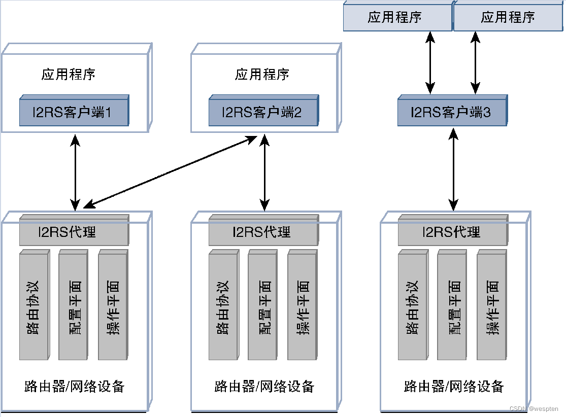
I2RS (Interface to the Routing System, routing system interface) is a working group of IETF that supports the implementation of hybrid SDN. Its purpose is to provide a method to programmatically access, query and configure routing infrastructure on network devices. The position of I2RS is that there is no need to move the control plane completely out of the network equipment, as with the original SDN proposal. I2RS proposes a way to influence distributed routing decisions, monitor devices and push policies to devices, addressing issues such as lack of device programmability, insufficient automation capabilities, and vendor lock-in.
I2RS defines a proxy and a client. The I2RS agent runs on the network device and communicates with LDP, BGP (Border Gateway Protocol, Border Gateway Protocol), OSPF (Open Shortest Path First, open shortest path first), IS-IS (Intermediate System to Intermediate System, intermediate system to intermediate system ), RIB manager, and routing components such as the operation plane and configuration plane of the device to interact.
The I2RS proxy can provide read and write access capabilities for the I2RS client running on an independent device, allowing the I2RS client to control routing parameters or retrieve routing information by querying the I2RS proxy. In addition, the I2RS client can also subscribe to event notifications from the broker, so changes in any subscribed routing components can be delivered from the broker to the client in a push model.
The proxy defined by the I2RS architecture is required to support and process requests from multiple external clients. The I2RS client can either be embedded code in the application or be located between the routing device and the application, as shown in the figure below.
4. Northbound protocol
The northbound protocol is the interface between the SDN controller and upper-layer applications, as shown in the figure below.

Applications typically perform service orchestration functions or make and implement decisions based on application-defined logic or policies. Communication between an SDN controller and an application is no different than communication between two software entities, and thus does not require any special new protocols. Many protocols in use today enable northbound communication, such as RESTful APIs or libraries in programming languages such as Python, Ruby, Go, Java, C++, etc.
5. Rediscuss NETCONF, RESTCONF and YANG
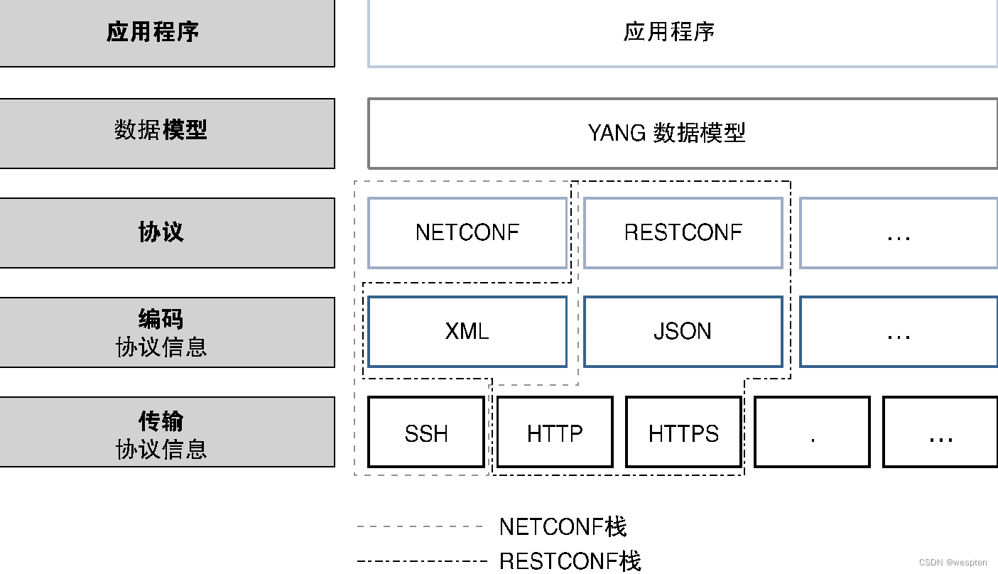
As mentioned earlier, both NETCONF and RESTCONF use the data modeling language YANG for information exchange. No discussion of these protocols would be complete without an analysis of the encoding techniques and transport mechanisms they use. The following will first analyze the relationship between these protocols.
As can be seen from the figure below, data (including operation data, configuration data, and user data) plus programming logic and analysis modules constitute the recipe of the application (note: the recipe file contains information about the given software), if the application If the program wants to configure network devices, it can use a data modeling language such as YANG to construct configuration information.
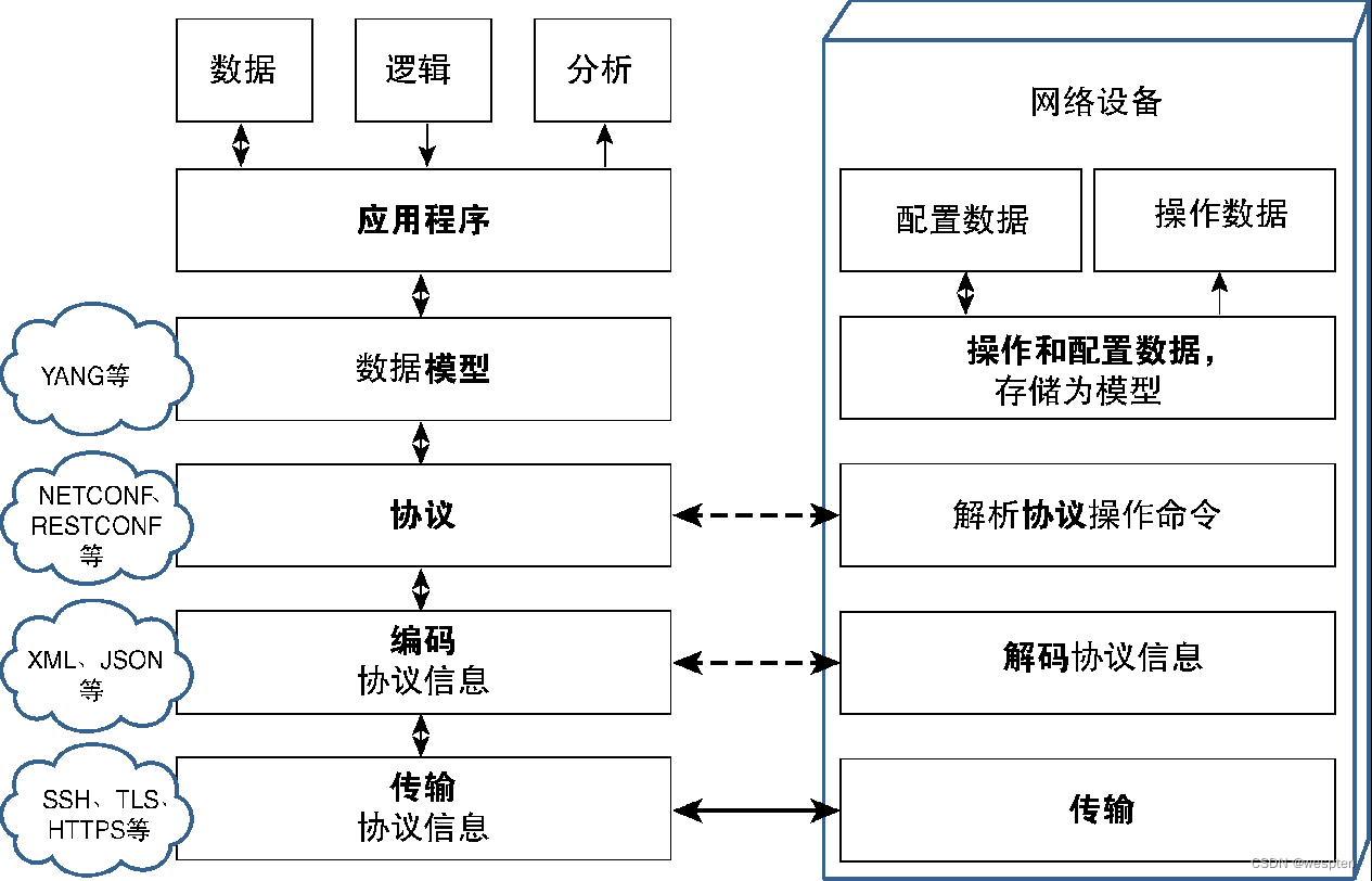
After the configuration information is constructed, the configuration protocol (such as NETCONF) can use the data to define the type of operation to be performed. For example, after delivering the configuration data, NETCONF can execute the edit-config operation). Next, the operation and data mode information of the protocol must be encoded, and finally the transmission protocol (such as SSH [Secure Shell, secure shell], HTTPS and TLS, etc.) is used to transmit the information.
Network devices need to have the ability to communicate using the same transport method. Similarly, network devices need to decode these protocol message data and pass them to the protocol code to determine the type of operation that must be performed. Network devices are required to understand the data modeling language used and recognize configuration and operational data within a predefined structure. Since the data model used by both the application and the device is the same, parameters and fields related to the data being exchanged can be easily parsed.
The differences between data models, protocols, and codecs can be challenging for the first time.
For example, while YANG data modeling can be expressed in JSON format, it should not be confused with protocol encoding. To better understand these concepts, use an analogy with people's everyday interactions.
- Transmission medium: air.
- Coding: phonemes and sounds.
- Transmission medium: air.
- Coding: phonemes and sounds.
- Protocol: The language used (eg English).
- Data model: grammatical structure (words in a language have no meaning if they are not formed into correct sentences).
- Application: Tongue and ear, the language and auditory organs of human beings.
- Data Logic Analysis: The Human Brain.
On this basis, we can further analyze NETCONF and RESTCONF. Both are very popular and widely used configuration protocols that leverage cross-platform, cross-vendor standard applications to configure network devices.
Both NETCONF and RESTCONF use YANG as the data modeling language, and both are standardized through RFCs. NETCONF tends to use XML as the encoding technique, while RESTCONF often uses JSON-based and XML-based encoding techniques.
At the transport level, the NETCONF standard recommends adopting a secure, authenticated transport protocol that can provide data integrity and security. Although it has certain flexibility, SSH is still listed as one of the mandatory options. The common transmission protocol of RESTCONF is HTTP, but many transmission protocols such as HTTPS are also used.
The diagram below lists the relationship between these modules and common options for RESTCONF and NETCONF.
6. More information about the YANG model
Ideally, the YANG model of all functional properties and operational data can be fully standardized. In fact, through the continuous efforts of the IETF, a common standard YANG model has been provided for different functional features and configurable parameters. Although these IETF YANG models can achieve seamless work across vendors, the disadvantage is that they cannot support vendors to target configuration parameters. Or various enhanced functions for manipulating data.
As can be seen from the figure below, many vendors have developed (or modified based on the standard model) separate YANG models. These models are usually called native YANG models, which are more suitable for the vendor's own implementation. These YANG models will be released to the public repository for import and use by application developers. While this approach deviates from standard approaches, it is very realistic and retains flexibility and openness.
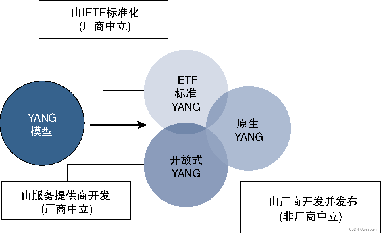
The third type of YANG model is the YANG model promoted by service providers. Under the leadership of the OpenConfig working group, service providers believe that the standardization time of IETF is difficult to meet their needs, and sometimes they are too affected by manufacturers, so service providers Vendors have also started to develop and release their own YANG models to fill the gap.
The YANG models mentioned above are all network element-level models, which can represent the configuration information of functional characteristics or the structure of operation data (such as the bit rate of the interface or the routing scale of the protocol). These YANG models all work at the network element level.
It is worth mentioning that the YANG model can also define a complete network service. This type of service-level YANG model can describe the structure and parameters of the entire service (such as L3VPN service or VPLS service). The orchestrator can use this model to implement the entire service. Although IETF drafts define many such YANG models, in many cases vendors or providers are developing their own models to meet specific service deployment needs.
The following figure shows the relationship between these two types of YANG models:

4. Detailed explanation of SDN controller
The main role of the SDN controller and the various protocols used have been introduced above. Next, the common SDN controllers available at present will be discussed, including open source SDN controllers and commercial SDN controllers provided by network equipment suppliers.
All SDN controllers should have the following functions:
- Provide the ability to communicate with various network devices, which can be realized by supporting multiple SDN southbound protocols.
- Provide open and/or well-documented northbound APIs to develop applications capable of interacting with SDN controllers.
- Maintain a global view of the network.
- Provides network event monitoring capabilities and the ability to define response actions in response to these events.
- Provides the network with the ability to perform path computation and decision making.
- Provides high availability capabilities.
- Provides modularity and flexibility mechanisms that allow the network to be programmed and customized to meet changing requirements or emerging protocols. It is imperative to ensure the scalability of the SDN controller, capable of growing as demand grows.
Some of the common SDN controllers currently available are discussed in detail next.
1. Open source SDN controller
There are many open source SDN controllers available from vendors and the open source community. Similar to other open source software, these controllers do not have any licensing costs, and anyone can take the code and use it as is or modify it as needed. Of course, these advantages all depend on the support and development capabilities of the open source community.
Some common open source SDN controllers are discussed below:
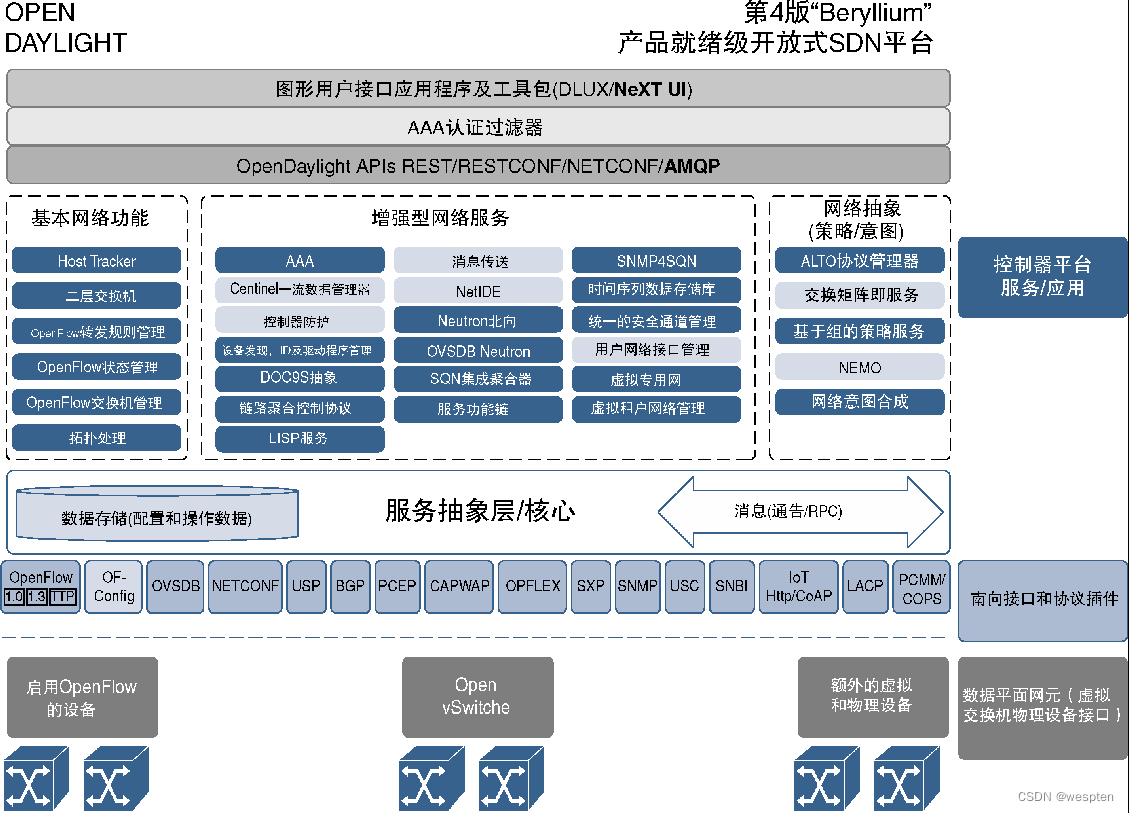
1. ODL(OpenDaylight)
The OpenDaylight Foundation is a forum mainly established by network providers to provide an open SDN platform and support multi-vendor network environments. The foundation is responsible for developing and maintaining the OpenDaylight SDN controller, which has become the de facto standard for open source SDN platforms in the networking world.
ODL adopts micro-service architecture, which has the characteristics of modularization and flexibility, and only needs to install the necessary protocols and services. ODL supports a variety of common southbound protocols (such as OpenFlow, PCEP, BGP, NETCONF, SNMP, and LISP [Location/ID Separation Protocol, Location/ID Separation Protocol]) and northbound APIs (such as RESTCONF), for many southbound protocols The support capability of ODL makes ODL very suitable for semi-open deployment environments, because these deployment scenarios may require the use of specific protocols. ODL is a pure software product that runs on top of Java as a Java virtual machine.
The following figure shows the ODL architecture diagram:
Since ODL is open source software, many suppliers (such as HP, Cisco, Oracle, etc.) are contributing their own software to the ODL code, mainly to support the interaction between ODL and their own devices. There are also some suppliers who develop their own ODL products on the basis of open source ODL, support more additional functions, and provide technical support as commercial products.
The version of ODL is named after the periodic table of elements. The first version, Hydrogen, made its debut in early 2014. The subsequent versions are Helium, Lithium, and Beryllium. So far, ODL has provided a fifth available version called Boron.
2. Ryu
Ryu is an open source SDN controller supported by the open source community. It is written entirely in Python, based on a component approach, and has a well-documented API, making it easy to develop any application to interact with it. Ryu can support major southbound APIs such as OpenFlow, OF-CONFIG, NETCONF, and BGP through the southbound library.
Ryu supports multi-vendor network equipment and has been deployed in the data center of NTT (Nippon Telegraph and Telephone, Nippon Telegraph and Telephone Company).
The following figure shows the deployment architecture based on the Ryu SDN controller:

3. ONOS
ONOS (Open Network Operating System, Open Network Operating System) is a distributed SDN operating system that can provide rich high availability and carrier-level SDN. ONOS emerged as an open source software approach in 2014, aiming to provide service providers with an open source platform for building software-defined networks. At present, ONOS has been widely supported by a large number of service providers, suppliers and other partners, and a large number of new members continue to join the ONOS community.
The figure below shows a schematic diagram of the ONOS architecture, which emphasizes the distributed core of ONOS, which is the fundamental reason why ONOS has high availability and flexibility to meet the carrier-level standards.
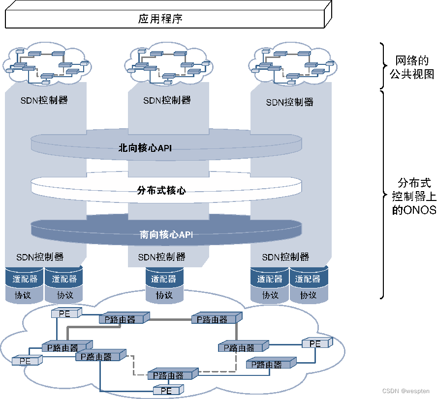
The distributed core layer is located between the northbound core API and the southbound core API. The purpose of these two core APIs is to provide protocol-independent APIs for the distributed core from their respective directions. The distributed core is responsible for the coordination of the entire cluster, processing state management and data management operations initiated from the northbound and southbound cores, ensuring the coordinated work of various controllers across the network, while maintaining a public view based on the entire network view, while Not just an isolated view based on visibility, all applications interacting with ONOS can have a public view of the network, which is also the core advantage of the ONOS distributed architecture.
ONOS adopts pluggable adapters on the southbound core API and supports a variety of popular SDN southbound protocols, so it is extremely flexible. The northbound API allows applications to interact with and use ONOS without having to understand the deployment of distributed ONOS.
The version name of ONOS is named after a bird, and the logo of ONOS is also a bird graphic.
So far, the latest version of ONOS is called Hummingbird. One of the common ONOS applications is to include ONOS in a project called CORD (Central Office Re-architected as a Datacenter). The purpose of CORD is to accelerate the adoption of SDN and NFV technologies by suppliers.
4. OpenContrail
OpenContrail is an open source SDN platform developed by Juniper, which aims to implement SDN through the overlay model. OpenContrail adopts network virtualization technology to decouple the forwarding function (such as MPLS or VXLAN) of the overlay network from the data forwarding function, and the control function is handled by the SDN controller.
Currently, OpenContrail complies with Apache 2.0 and supports additional functions such as virtual routers and common northbound APIs.
2. Commercial SDN controller
Many SDN controllers have commercial versions. These commercial SDN controllers come not only from network equipment suppliers, but also from many new entrants in the industry. They hope to gain network market share by providing better and more profitable SDN controllers . As mentioned above, many suppliers implement their own SDN controllers based on ODL and provide enhanced functions, evolution routes, and technical support. Of course, some suppliers also develop their own SDN controllers from scratch.
Common commercial SDN controllers are as follows:
1. VMware NSX
VMware NSX was the first SDN controller developed by a vendor, originally developed by a startup called Nicira, which was later acquired by VMware. The NSX platform uses an overlay network to implement SDN. It can create a VXLAN-based overlay network and also supports routing, firewall, switching, and other network functions. The NSX SDN platform can be used with any hardware and hypervisor to provide end users with all network logic functions, such as logical load balancers and logical routers, while also providing flexible programmable networks.
2. Cisco SDN Controller
Cisco has developed a variety of SDN controllers to meet the needs of different market segments. Initially, Cisco developed an open Cisco XNC (eXtensible Network Controller, extensible network controller), which can support southbound communication through Cisco's onePK protocol, and later joined other suppliers and became a founding member of ODL one. Cisco supports a commercial version of ODL called Cisco OSC (Open SDN Controller, Open SDN Controller). OSC is built on ODL and supports standard southbound and northbound APIs and related protocols.
Cisco's SDN controller solution for data centers and enterprises is called APIC (Application Policy Infrastructure Controller, Application Policy Infrastructure Controller), and the enterprise version of APIC is APIC-EM (APIC Enterprise Module, APIC Enterprise Module).
The data center version of the APIC is called APIC-DC (APIC Data Center, APIC Data Center) and is part of the Cisco ACI ecosystem, which uses Cisco proprietary solutions. The Cisco APIC-DC is the core component of the ACI solution, supporting functions such as network programmability, management and deployment, policy enforcement, and network monitoring. APIC-DC provides GUI and CLI interfaces to realize northbound interaction, and supports proprietary protocol iVXLAN (implementing SDN through VXLAN overlay network) and standard OpenFlex protocol (developed by Cisco and become an open source protocol) for southbound communication.
In addition, Cisco also provides an open and standardized SDN controller called Cisco VTS (Virtual Topology System, virtual topology system), which is used for the management and configuration of overlay networks. VTS uses MP-BGP EVPN (Multi-Protocol BGP Ethernet Virtual Private Network, multi-protocol BGP Ethernet virtual private network) provides SDN overlay function. Cisco VTS supports REST-based northbound API to integrate with other OSS/BSS, and also supports rich southbound protocols, such as RESTCONF/YANG, Nexus NX-OS API, etc.
In the VxLAN-based network deployment solution, the Layer 2 address is carried on the Layer 3 transmission system. There are two ways to learn the Layer 2 MAC address of the terminal host: using the flooding and learning mechanism of the data path or exchanging the MAC address by using the control protocol. MP BGP EVPN uses the control protocol mode, and MP BGP provides the function of exchanging MAC addresses between different VxLAN endpoints.
3. Juniper Contrail
The commercially supported version of the open source OpenContrail SDN platform provided by Juniper is Juniper Contrail, as shown in the figure below.

Like OpenContrail, the commercial version implements SDN by supporting an overlay model, working with an existing physical network and deploying a network virtualization layer on top of it. Contrail supports southbound communication using XMPP as well as NETCONF, BGP and Juniper's virtual router (vRouter).
Juniper exited the ODL project in 2016 and currently supports Juniper Contrail and OpenContrail as its SDN controllers.
4. Big Network Controller
Big Switch Networks is one of the few companies that entered the SDN controller market early and contributed 3 important projects to the SDN open source community.
- Floodlight: Open source SDN controller.
- Indigo: Supports OpenFlow in physical and virtual environments.
- OFTest: A framework for testing OpenFlow conformance on switches.
In terms of business, Big Switch's SDN controller has developed from the original Floodlight project to a market-oriented Big Network controller. This controller supports standard southbound protocols (such as OpenFlow), adopts the classic SDN implementation method, and can communicate with physical Devices and virtual devices work together.
5. Nokia Cloud VSP
Nokia provides SDN controller solutions through Nuage VSP (Virtual Service Platform, virtual service platform). This product was originally developed by Nuage Networks, was later acquired by Alcatel-Lucent, and is now part of Nokia.
VSP mainly includes three components. VSC (Virtual Services Controller, Virtual Service Controller) is the main SDN controller, which is used to program the data forwarding plane and supports the OpenFlow communication protocol. The VSC communicates with the northbound VSD (Virtual Service Directory, virtual service directory) through XMPP, and the VSD is a policy engine. Similar to Open vSwitch, Nuage also has a VRS (Virtual Routing and Switching, virtual routing and switching) platform, which is integrated with the Hypervisor that provides network functions.
6. SD-WAN controller
As mentioned earlier, SDN is gradually penetrating into all levels of the network, and one of the important application areas is SD-WAN. At present, several suppliers have clearly provided usable SD-WAN controllers. The controllers are all similar in architecture, so they are described here in general terms.
At present, the enterprise WAN market has just begun to adopt SDN technology. In addition to traditional suppliers, there are many new entrants trying to occupy this market. The SD-WAN controllers provided by large companies on the market include Cisco’s APIC-EM, Riverbed’s SteelConnect and Viptela's vSmart Controller.
The main functions of these products are as follows:
- Cisco APIC-EM, the feature-rich SD-WAN solution is part of the Cisco IWAN (Intelligent WAN, Intelligent WAN) solution.
- Works with any WAN link technology.
- Leverage DMVPN for site-to-site communication.
- Riverbed SteelConnect。
- Utilize the application database directory to direct traffic on different WAN links, bringing value-added services to customers using cloud application products such as MS Office365, Salesforce and Box.
- Using Riverbed's SteelHead CX platform to provide SaaS services can dynamically create virtual machines closer to branches or end users, thereby providing advantages such as low latency, low jitter, and high-speed access.
- Viptela vSmart Controller。
- The SD-WAN solution is part of the Viptela SEN (Secure Extensible Network) platform, which also includes the vManage application for managing the network and vEdge routers.
- Simplify deployment and management operations, and realize plug-and-play of access devices.
- The control plane and data plane communicate through a proprietary protocol.
- The controller and configuration management software are free, and customers only pay for the edge hardware system.
- Use L3VPN for inter-site communication.
5. SDN Application Cases
SDN was originally considered to be a solution dedicated to data center scalability and traffic control problems. Later, this new technology gradually entered many network fields and achieved certain applications in these fields.
Considering that the protocols and technologies used by SDN in different network fields are different due to different specific solutions, here we will analyze the role of SDN in these fields from five different network fields, as shown in the figure below.

1. SDN in the data center (SDN DC)
While data centers have been around since the days of mainframes, they have grown exponentially in size and capacity over the past decade or so. The emergence of the Internet and the cloud and the trend of service providers maintaining online businesses to meet consumer demand have greatly promoted the explosive growth of data centers, resulting in large-scale data centers with thousands of servers installed, which are deployed on tens of acres On the land, several megawatts of electricity resources are consumed.
1. Issues and Challenges
The development of data centers is the main driving force for server virtualization. Although virtualization has improved the space utilization rate, energy consumption level and cost efficiency of the computer room, it has also brought new and severe challenges to the network architecture interconnecting these virtual servers.
One of the challenges is that the scalability of VLAN (Virtual LAN, virtual LAN) is limited to 4096. Virtual servers are usually located in the same Layer 2 domain. VLANs need to be used to isolate these virtual servers to support multi-tenant applications, and enterprises The proliferation of cloud-hosted services has also created the need to stretch enterprise VLAN domains across multiple data centers, putting enormous pressure on available VLAN space.
In order to solve this problem, a VXLAN (Virtual Extensible LAN, Virtual Extensible LAN) protocol is introduced. VXLAN can provide layer-2 adjacency for virtual servers through a layer-3 network. The overlay network established by VXLAN using VXLAN ID can be expanded to a maximum of 16 million network segments, thus solving the scalability problem mentioned above. However, VXLAN also brings new challenges, namely the management, monitoring and programming of the overlay network.
The following figure shows a VXLAN-based overlay network:

2. SDN solutions
The endpoint of the VXLAN overlay network (that is, the VTEP [VXLAN Tunnel End Point, VXLAN tunnel end point]) is usually located on the ToR (Top of Rack, Top of Rack) switch or the virtual switch of the host. In both cases, the VTEP needs to be programmed and communicated with Tenant virtual machines are associated.
Virtual machines in large-scale data centers are deployed using orchestration tools, such as OpenStack, which can deploy VMs in an automated manner, so virtual machines can be deployed on any physical server. However, in order to connect to the network through VXLAN, it is necessary to provide a corresponding mechanism to view the entire network. At this time, SDN is used, because SDN has a complete network view, and can also coordinate with virtual development tools. For the forwarding plane (located in the ToR or virtual switch) for programming VTEP and VXLAN information.
As can be seen from the figure below, the SDN control communicates with the switch and creates a VTEP interface based on the virtual machine configured on the server served by the switch.
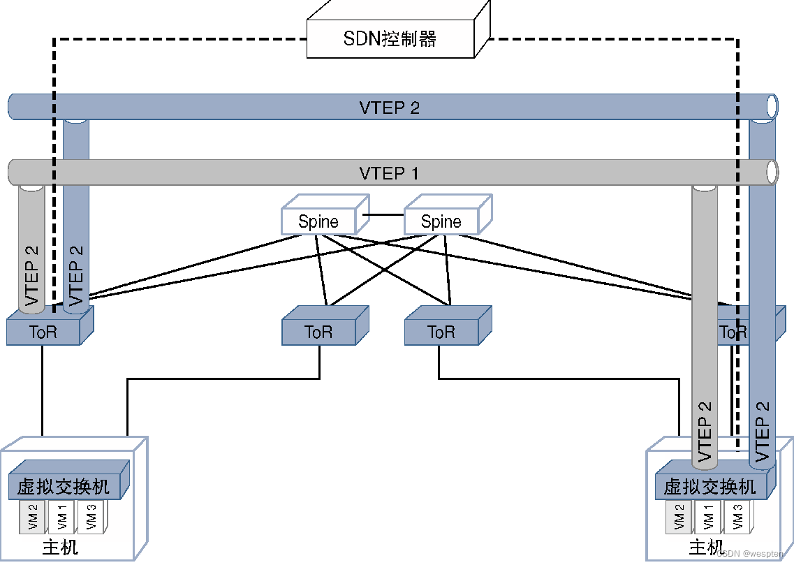
Since virtual machines may be moved or removed between physical servers, there may be a need to reprogram or delete VTEP information, which is also handled by the SDN controller.
2. SDN in service provider network (SP SDN)
From a high-level perspective, the routing devices in the SP (Service Provider, service provider) network can be divided into PE (Provider Edge, provider edge) and P (Provider, provider) routers. PE routers are directly connected to customer networks, so PE routers have a large number of interfaces, and perform various operations such as classification, QoS, access control, fault detection, and routing. These routers usually carry a large amount of customer routing information and ARP cache to form a service provider network. borders. PE routers usually aggregate traffic to P routers through high-bandwidth upstream links.
The functional characteristics of the P routers are not complicated, and the number is relatively small, but the P routers need to be interconnected through large-bandwidth links provided by geographically dispersed POP points. For most SP networks, services such as voice, video, data, and Internet generally use public core links and core routers, and these core links carry the aggregation of a large number of customers served by service providers. Traffic, any interruption of large-bandwidth links will have a serious impact on a large number of users, so in order to avoid failures and provide carrier-class availability, physical redundancy is usually deployed for these core links and the core routers interconnected through these links mechanism.
1. Issues and Challenges
Since SP traffic faces a large number of redundant links, nodes, and paths, the shortest available path between nodes may not usually be the path with the best cost per bit, or may not be able to carry all the traffic at once. Therefore, a common practice for SPs is to use traffic engineering technology to direct traffic to specific paths based on factors such as importance, cost, delay, and network status, thereby optimizing network costs and achieving better performance.
The figure below shows a generic view of an SP network and illustrates how traffic engineering tunnels can be used to direct traffic from the best path to the user's preferred path.
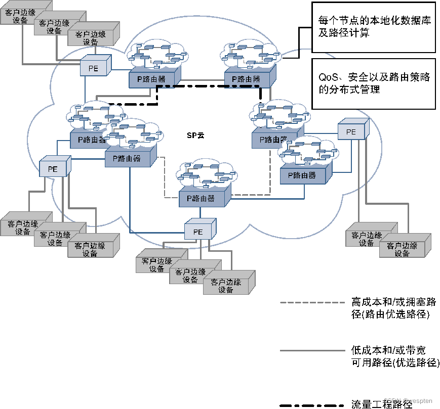
As mentioned above, the optimal routing path may not be the preferred traffic path (considering factors such as cost, delay, bandwidth availability, etc.), and the behavior of routing protocols will be changed to meet specific needs through specific traffic engineering techniques. MPLS-TE (MPLS Traffic Engineering, MPLS traffic engineering) is a commonly used technology to achieve such goals, and SR-TE (Segment Routing Traffic Engineering, segment routing traffic engineering) has also been widely used.
For these two protocols, not all nodes have end-to-end views such as network link bandwidth, link preference, shared fault groups (such as links sharing the same transmission equipment), and switching information of traffic engineering paths. Coordination between nodes using special protocols or protocol extensions is required to exchange this information and determine the complete traffic engineering path.
Each node performs path calculations and makes decisions, so the required data must be persisted on all nodes. Since these operations all consume a large amount of CPU resources and memory, and this distributed implementation mechanism also needs to perform end-to-end coordination operations, these overheads will occupy a large amount of device resources.
Another challenge for SP networks is the extent of impact on the network and services in the event of a potential failure. Although FRR (Fast Re-Route, fast rerouting) and other mechanisms can be deployed, when network capacity planning and QoS guarantee requirements are added, the entire network design work will become very complicated and difficult to optimize.
2. SDN solutions
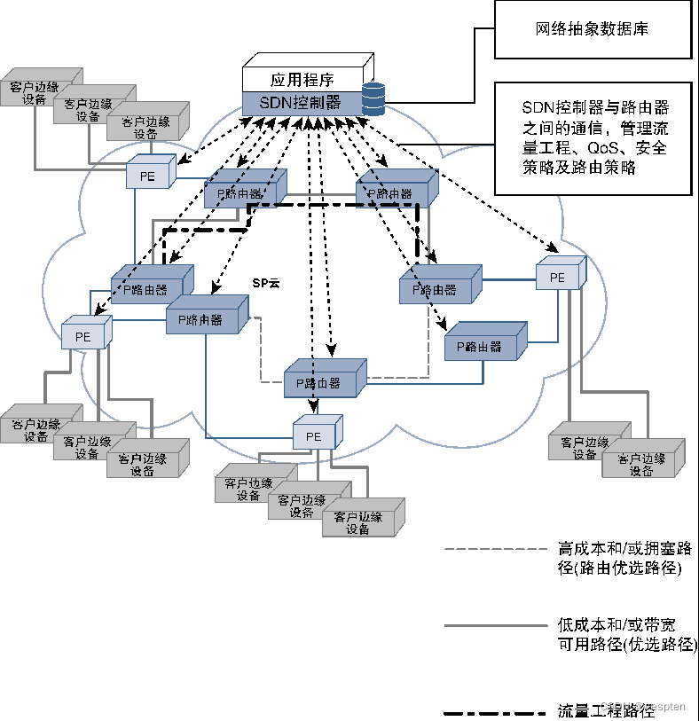
Traffic engineering management and design challenges across networks can be effectively addressed by using a centralized controller because it has a network-wide link-state view and can also track bandwidth allocation and allow the controller to handle the decision-making process.
SDN is perfect for this scenario. For SDN-based solutions, routers do not need to make decisions or keep databases required for decisions, thus greatly reducing the memory and CPU resource overhead of routers. The centralized SDN controller can completely go beyond the basic decision-making criteria based on traffic and link utilization, and interact with high-level applications to implement policy-based traffic rerouting, such as pre-carrying out traffic rerouting before the maintenance window arrives, according to a day Change the direction of traffic at specific times or events in the network, or dynamically change the bandwidth allocation scheme for specific traffic flows to meet temporary needs.
A centralized controller is also useful for managing feature-rich PE routers. When configuring new customers on the PE router, you can configure consistent QoS, security, scalability, and connectivity experiences for these customers according to SLA (Service Level Agreement) requirements. Specific data streams have a higher preference), then configuration change data can be easily and consistently pushed to all edge routers in the SP network through the centralized SDN controller, as shown in the figure below.
Another major advantage of the SDN solution is to improve the security and high availability of the SP network. If the service provider network is suffering from a large-traffic DDoS (Distributed Denial-of-Service) attack (attacking the SP network or customers hosted on the SP network), then the centralized SDN controller can be used to block the attack Traffic deviates from the standard routing path and is redirected to centralized or distributed traffic cleaning devices, thus effectively protecting the SP infrastructure.
3. SDN in wide area network (SD WAN)
The networks of enterprises and their business customers are distributed in different geographical locations, and many branches must be connected to the network of the headquarters. These sites are connected to different offices through dedicated WAN (Wide-Area Network, wide area network) circuits (such as T1 or T3) or dedicated lines provided by VPN (Virtual Private Network, virtual private network) service providers. The prices of these links or services All are very expensive, greatly increasing the operating expenses of the enterprise network. In order to reduce costs, many enterprises use new technologies such as DMVPN (Dynamic Multipoint VPN) or MPLS VPN to transfer these network connections to secure Internet links. After the data encryption protection mechanism is added, the dynamically established overlay network can use the shared Internet link to provide services for the enterprise's private traffic.
However, Internet connections may not have guaranteed SLAs, and even with encryption, may not be suitable for transmitting highly sensitive corporate data, so while this approach reduces the bandwidth requirements of the dedicated link, it does not completely eliminate the need for a private WAN. link requirements. Traffic can be directed to Internet links or dedicated WAN links based on SLA needs or data sensitivity requirements.
In addition to the main leased line link, using this shared Internet provider link, customers can connect different branches and headquarters in a cost-effective manner, as shown in the figure below.
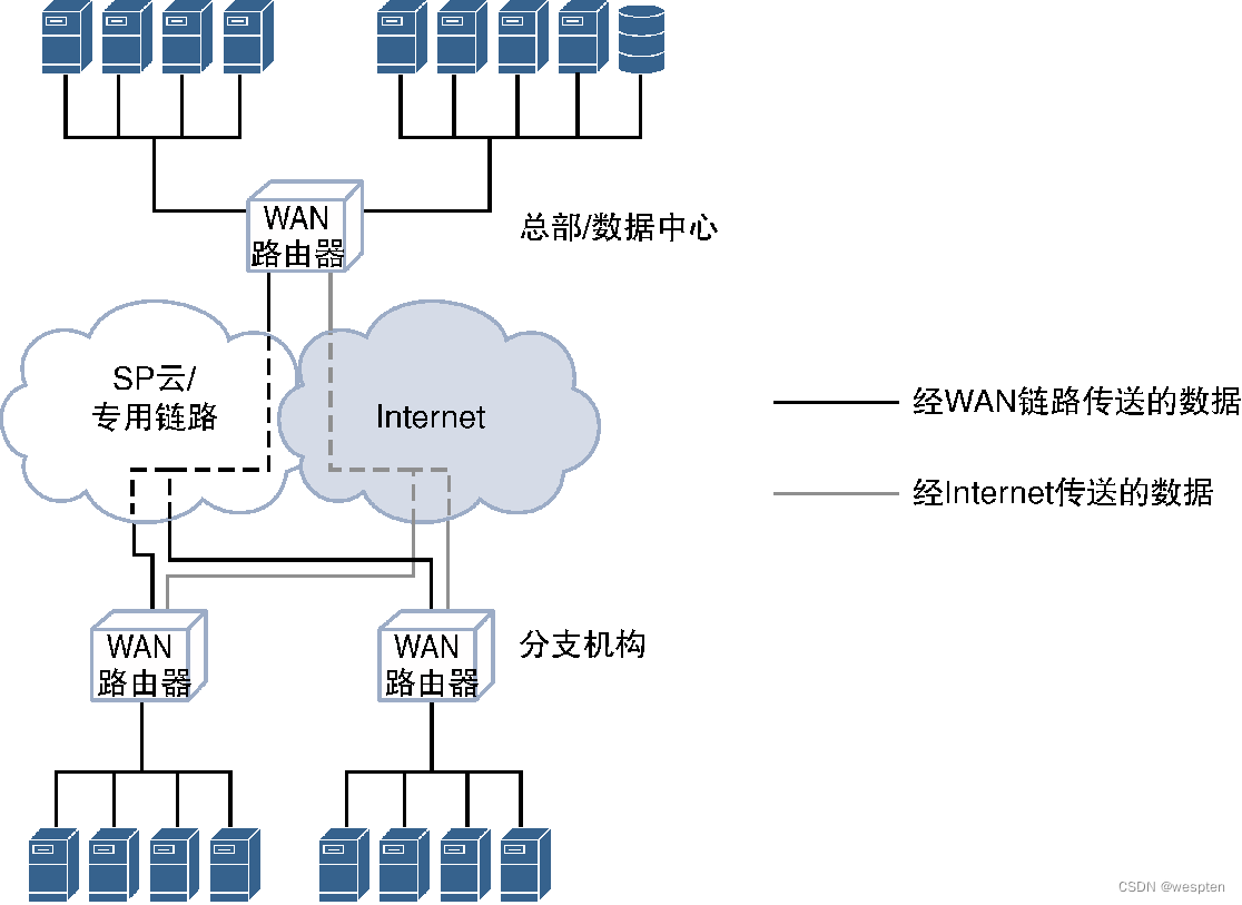
1. Issues and Challenges
For large-scale WAN deployments with hundreds or thousands of sites, maintaining interconnectivity between branches while using separate leased and interconnect links is a complex task. Task. Additionally, the need to manage traffic policies at each site location for the types of traffic that can be directed onto the Internet link constitutes a significant administrative overhead alone.
Optimizing these policies based on real-time metrics or dynamically adjusting them frequently is not trivial. While the relationship between cost and performance is clear, it's impossible to pursue such an effect without a management system that can centrally manage traffic flow and configure WAN routers.
2. SDN solutions
Using the SDN model of centralized network topology, the WAN with multiple links can be abstracted into a centralized management system (called a controller), and the controller can monitor the SLA on the Internet link and instruct the branch or headquarters Use the correct link to transmit data, and manage the traffic flow according to the type and sensitivity of the traffic, so that different traffic uses the dedicated line circuit and the Internet link respectively.
Another advantage is that it can improve the link utilization of the remote router and make effective routing decisions for the traffic flow leaving the source router. Therefore, SDN solutions can effectively save operating costs, which is extremely difficult to achieve with traditional solutions. We call this solution the SDN solution for WAN, or SD WAN for short. Common commercial SD WAN products mainly include Viptela's vSmart, Cisco's IWAN, or Riverbed's Steel-Connect.
The following figure shows a schematic diagram of the SD WAN solution:

It can be seen that the centralized SDN WAN controller is responsible for managing WAN routers, monitoring uplink performance and centrally managing traffic policies to change traffic paths based on factors such as link performance, traffic characteristics, and time.
4. Enterprise SDN
An enterprise network usually consists of network devices connected across local LANs and WANs. Depending on the size of the enterprise, the LAN can connect computers, printers, voice/video terminals, and other network devices wirelessly and wiredly.
If you want to connect remote branch offices or data centers, you can configure a dedicated WAN link or Internet link for the WAN connection. Enterprise networks typically deploy multiple services, such as voice networks for internal and external communications, data networks to connect local users, and data storage in private data centers or public clouds. In addition, large enterprise networks often segregate enterprise networks based on departmental differences such as engineering, finance, marketing, sales, and partners.
The following figure shows the network deployment of a typical enterprise network:

1. Issues and Challenges
For the actual network environment, it may be necessary to access the enterprise network from the LAN, or it may be necessary to access the enterprise network from the WAN. At this time, different control strategies must be deployed for the enterprise network. It is very important for network architecture. In addition, after an enterprise deploys a private cloud-based network architecture, the original network access control mechanism, firewall policy, and security measures must be adjusted and improved in a targeted manner, so as to fully enjoy the benefits of the private cloud deployment solution.
With the continuous emergence of a large number of new business agility models (such as BYOD [Bring Your Own Device, bring your own device office]) and the massive popularity of computing devices (such as laptops, mobile devices, and tablets, etc.), and access from any device The capabilities of enterprise networks continue to grow, and enterprise IT departments must support all demands without compromising the network.
In essence, the security policy of network access is a dynamic policy, which is extremely complex. For example, different security processes need to be deployed when users access devices (such as laptops running multiple operating systems). The network transport layer needs to adopt VPN and security encryption mechanisms, while data center servers need to deploy data privacy protection mechanisms. User policies need to be deployed on all user access points, and QoS policies must also be deployed on the entire network.
Since the enterprise network deploys the network transmission mechanism of wireless and mobile devices, and the network access is flexible and changeable, all these policies must be deployed on the access port at the edge of the network to which the user is connected.
2. SDN solutions
Leveraging SDN's centralized view of the network and its ability to program the entire network from a single source can address the challenges facing enterprise networks.
BYOD allows employees to bring their own personal devices, such as laptops or smartphones, to the office and have the same access to the corporate network as corporate-provided devices. Sometimes people refer to BYOD as IT consumerization.
For BYOD, after these devices are connected to the network, the SDN controller can detect them, and then issue appropriate configuration files according to the user or device type, so as to enforce the corresponding access policies on the devices, and at the same time, through appropriate The policy mechanism programs the network edge and the transport layer.
Through this method of creating dynamic policies from a centralized source, enterprise customers can allow their users/employees or partners to access the corporate network from any location without being limited to a specific physical office/desktop. Without the SDN model, IT staff would have to dynamically configure QoS/security policies on the network for each device or user, which would be an extremely tedious task. This traditional approach to dynamic provisioning is nearly impossible for an enterprise with thousands of employees spread across multiple locations.
In addition, SDN can also play a very important role in protecting the enterprise network from DDoS or other security attacks. As long as the attack signature is detected or learned from any source, the SDN controller can prevent attacks on the entire network, thereby Provide security protection for enterprise data.
A common case is to use BGP-FS to process DDoS attack traffic. As long as the SDN controller recognizes the attack traffic, the BGP server running on the SDN controller can find the attack traffic, and then the BGP server can use BGP-FS to request The edge device such as dropping or directing (for cleaning) all the traffic that matches the characteristics of the attack traffic. If there is no such method, RTBH (Remote Triggered Black Hole) can only be implemented by injecting static routes (which can only be matched according to the traffic destination) to adjust the routing of each edge device. Attack traffic is directed to the scrubbing center.
At present, more and more enterprise networks are gradually adopting this new SDN network architecture. SDN technology brings advantages such as self-service IT services to enterprises, and also reduces operating costs, and significantly enhances security and compliance.
5. Transmission SDN
The transmission network can provide a layer of connectivity infrastructure for the network POP (Point Of Presence, Access Point). CSPs usually use the transmission network to interconnect data centers, and network service providers use the transmission network to build networks between core routers.
The transmission network may belong to the same provider or an independent transmission network provider, usually including components such as optical fiber links, optical switches, optical multiplexers (MUX) and demultiplexers (DEMUX), and optical regenerators (REGEN), and have A large number of logical circuits that share a physical medium are separated by different wavelengths (usually called Lambdas), and these wavelengths/Lambdas can be separated or inserted into the transmission network at the ingress or egress of the logical network.
The following figure shows a simplified transmission network diagram:

The current transmission network has integrated MUX and DEMUX functions into a single device that can be reconfigured to determine the upper and lower wavelengths, called ROADM (Reconfigurable Optical Add-Drop Multiplexer, reconfigurable optical add-drop multiplexer).
The function of ROADM in the transmission network is very similar to that of the switch (Layer 2 switch, even label switching router) in the IP network. Since the optical link carries multiple wavelengths each time and uses the wavelength to determine the corresponding switching operation, the network composed of ROADM, REGEN, and optical links is also called a switched optical network based on WDM (Wave Division Multiplexing, wavelength division multiplexing). Web or WSON.
1. Issues and Challenges
Just as the switch maintains the MAC table or the MPLS router maintains the LFIB (Label Forwarding Information Base, label forwarding information base) table, the ROADM also maintains the corresponding table to determine how to switch, add and drop wavelengths from the composite optical signal.
Historically, the wavelength switching decision process was manually managed locally by the device, resulting in a long time spent configuring new circuits. In order to automate this process and allow devices to exchange control plane information, some independent protocols have been developed. Among them, it is worth mentioning GMPLS (Generalized MPLS) of IETF and ASON (Automatically Switched Optical Network) of ITU (International Telecommunication Union, International Telecommunication Union). The method is different.
GMPLS is based on MPLS-TE and other related protocols. The purpose is to generalize the MPLS protocol and work with optical networks. ASON is a new automated control plane architecture developed for optical networks. Since different vendors support these two methods to varying degrees, and there are many interoperability issues between different vendors, when adopting vendor heterogeneous deployment solutions, end-to-end information exchange and cross-transport There are still many challenges in the wavelength allocation and management of the network. Similarly, even in the homogeneous deployment of suppliers, there are certain restrictions on information exchange, and there is no centralized exchange, which faces similar inefficiency problems to the SP core network.
Note: wavelength selection is a very important processing step in the optical transmission network. It is necessary to select an available wavelength that can reach the destination according to the requirements. You can first select a wavelength from the starting node, and then convert it into a another wavelength. However, this implementation adds complexity and cost to the network due to the limited rate of switching and processing operations of the electronics, and also has a severe impact on transmission rates. Therefore, the network should maintain as much end-to-end optical operation as possible, enabling the use of higher power transmitters and better quality fiber to avoid regeneration.
In addition to wavelength availability, other factors affecting wavelength selection include signal attenuation or impairment and signal error rate. Exchange decisions. Unless all this information about the transport network is available, no device (ROADM or switch) can make optimal, fast and automated decisions about circuit switching.
2. SDN solutions
The centralized control plane solution provided by SDN can use the extracted network information to solve the various challenges mentioned above. The controller implementing the transmission SDN function can extract the wavelength and signal information from the optical equipment, so as to have a complete view of the available wavelength and the quality of the signal received at each hop, so that the optimal network can be calculated between the source end and the destination end. Optical signal exchange path, and program the ROADM, switch and relay equipment (signal regenerator) along the way.
The use of SDN in the transmission network not only greatly reduces the configuration time (from weeks to minutes), but also provides the possibility of rapid service recovery, detection and repair of service degradation, and optimal utilization.
Since each supplier may receive information or send instructions through different interfaces, it is necessary to develop a common YANG model to achieve this purpose and provide corresponding common interfaces. Efforts in this area also include OpenFlow, and many vendors support OpenFlow in their own implementations. In terms of standard formulation, OIF (Optical Interworking Forum, Optical Interworking Forum) has released a general API framework for transporting SDN, and proposed a follow-up evolution plan.
Standardization work in this area also includes PCEP protocol extensions, which have been proposed to ensure interoperability between PCEP and GMPLS networks, and as a protocol mechanism to consider the health of WSON networks when implementing path selection decisions.
6. SDN realizes virtualized network function NFV
SDN and NFV are two completely independent innovative technologies, but many of the goals of SDN are consistent with NFV, so the two can promote each other and cooperate with each other.
For traditional network equipment provided by vendors, the control plane, data plane, and hardware plane are all tightly integrated, as shown in the figure below.

There is no way to scale these planes independently, so the architecture does not have the flexibility to deploy new types of services or change their functionality. As can be seen from the figure, SDN and NFV work in two different dimensions. The focus of SDN is to realize the separation of the control plane and the forwarding plane, and to manage, control and monitor the forwarding plane through an independent control plane.
The focus of NFV is to separate network functions from hardware devices provided by suppliers, which helps to run software that implements network functions through general-purpose hardware.
Both SDN and NFV can provide flexible, scalable, elastic and agile network deployment mechanisms. Although these two technologies can be deployed independently, SDN principles can also be applied by virtualizing network functions and separating the control plane from the forwarding plane. in NFV.
The following figure reflects the synergistic relationship between the two. At this time, NFV uses commercial hardware and implements the forwarding plane of network functions, while the control plane functions are completed by the SDN controller. Applications can provide the glue for SDN and NFV to work together, maximizing the benefits of both technologies to enable a new network environment.
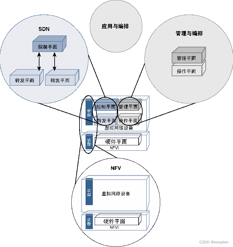
As can be seen from the figure below, after SDN, NFV, and applications cooperate with each other, they can fully meet the cloud expansion requirements in terms of on-demand expansion, optimization, deployment, and speed.
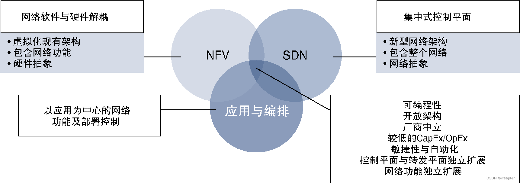
Service providers are all moving in this direction, hoping to improve their business advantages and rapidly deploy new services to end users. As the industry positively shifts, mainstream suppliers and new entrants are supporting this development and looking to become key players in new market segments.
Since both SDN and NFV provide a large number of open source tools, it is necessary to carefully evaluate these joint research projects to better use these tools. A typical case is the joint development of ON.Lab (Open Networking Lab, Open Networking Lab) and AT&T The research project named CORD (Central Office Re-Architected as Datacenter, End Office Re-Architected as Datacenter), the project will be introduced in detail below to show and explain the collaborative relationship between NFV, SDN and applications.
1. CORD: a collaborative case of SDN and NFV
CORD is a research project jointly initiated by AT&T Labs and ON.Lab. It hopes to provide a new system architecture for the transformation and upgrading of traditional telecom end offices. This platform can provide scalable and agile deployment solutions for next-generation network services. CORD takes SDN and NFV as the core components of the architecture, adopts open orchestration tools and programmability of applications, and combines related concepts of data center deployment architecture.
This combination of SDN and NFV provides a perfect technology integration case for the design, implementation and deployment of new network services. Both SDN and NFV are based on open source software and can break the boundaries of suppliers. This is well reflected in the CORD project. In essence, the core of the CORD project is to run on the general hardware of the supplier. implemented by open source software.
The entire CORD architecture includes hardware, software, and service orchestration functions. ONOS is used as the SDN controller, and network services are implemented by VNFs running on COTS hardware. OpenStack is responsible for performing NFVI orchestration functions. Finally, the open cloud operating system XOS combines these components in Together, realize the creation, management, operation and provision capabilities of network services.
The following figure shows a schematic diagram of the CORD architecture:
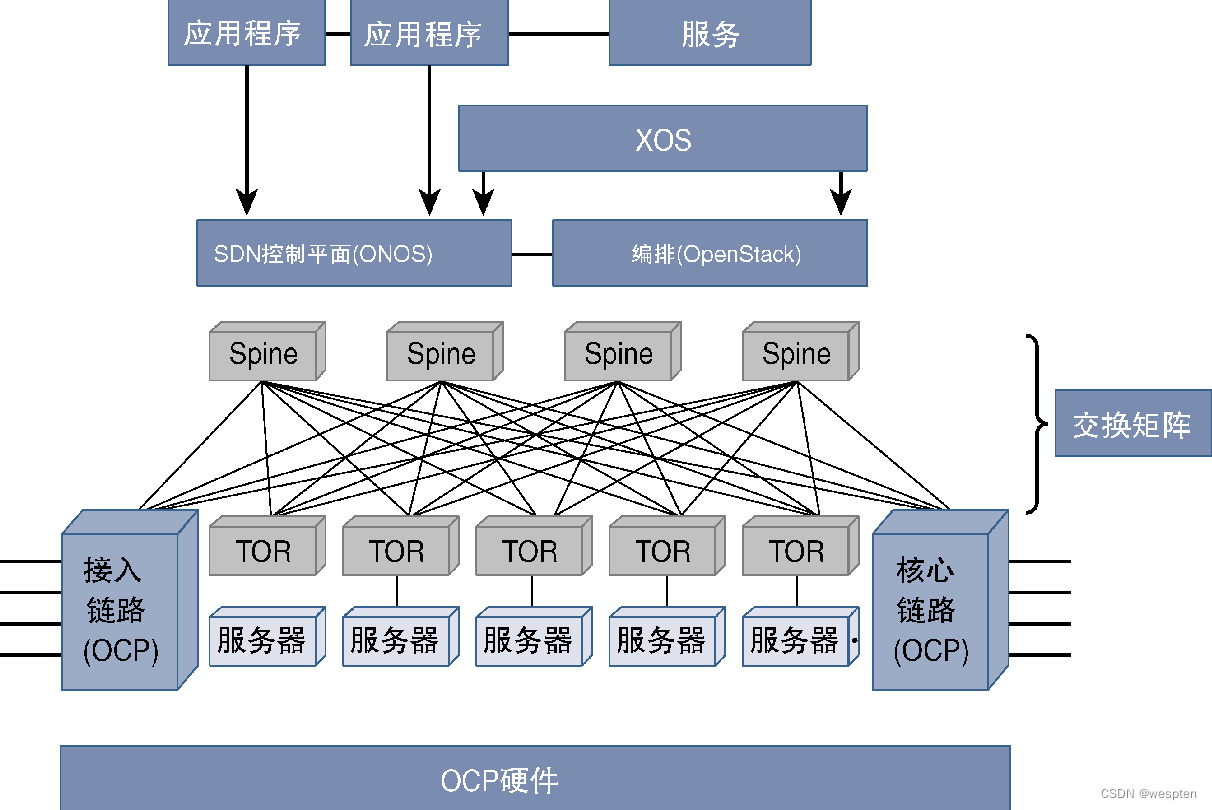
As can be seen from the figure, CORD's commercial server and underlying network adopt the spine-leaf architecture of the data center.
SDN controllers and applications perform control plane functions, while XOS and OpenStack perform service orchestration and NFVI orchestration functions, respectively.
The Open Compute Project was originally initiated by Facebook to develop effective design specifications for data center infrastructure resources (computing, storage, networking, switching matrix, power, and cooling, etc.). After two years of hard work, the project has greatly improved the energy efficiency level of Facebook's data center in Oregon, and the cost-effectiveness has improved significantly. Later, Intel, Rackspace, and other companies also participated in the project and called it the Open Computing Project.
The industry has begun to use the CORD infrastructure to actively explore the application demonstration of CORD in specific fields. For example, mobile providers are exploring the use of CORD for 5G mobile services, called M-CORD. M-CORD applies NFV by virtualizing MME (Mobility Management Entity, Mobility Management Entity), SGW (Serving Gateway, Service Gateway) and other modules into corresponding virtual equivalent components, and optimizes network utilization by using methods such as SD-WAN rate, directing traffic to the cache server or the Internet as needed. Other areas of exploration include E-CORD (Enterprise CORD, Enterprise CORD). E-CORD uses the concepts of vFW, vLB, and SDN to customize on-demand networks to enhance the programmability and adaptability of enterprise networks.
Next, introduce the application of CORD in the field of home broadband access. The traditional end office architecture that provides users with broadband access services originated in the TDM (Time-Division Multiplexing) era. With the rapid increase in access requirements, especially to provide users with Gigabit access services through technologies such as G.fast and GPON (Gigabit Passive Optical Network, Gigabit Passive Optical Network), it is necessary to adjust the design mode of traditional end offices to To meet the needs of various new service provision. The goal of CORD is to build a scalable, flexible and effective infrastructure to effectively provide various new services while reducing operating costs and equipment costs.
The following figure shows the system architecture diagram of a traditional PON (Passive Optical Network, Passive Optical Network) network. The optical fiber connecting users in the PON network (no matter where it is terminated) is a passive device, and multiple users share the same path to the connection. the uplink of the ingress port.
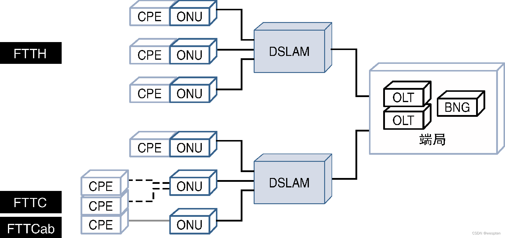
PON access technology can extend the optical fiber to the user's home. This access method is usually called FTTH (Fiber To The Home, fiber-to-the-home). At this time, user data can directly enter the optical fiber link and communicate with other FTTH users. Data is multiplexed on the same fiber link. There are many forms of optical fiber access in actual deployment. For example, only fiber optics are deployed near homes, and then twisted-pair cables are used to provide home users with access capabilities. This method is called FTTC (Fiber To The Curb, Fiber To The Curb).
Others include FTTB (Fiber To The Basement, Fiber To The Building), which is similar to FTTC but used for multi-building access, and uses DSL (Digital Subscriber Line, Digital Subscriber Line) technology from the user's home to the nearest telecommunications junction box. FTTCab (Fiber To The Cabinet, Fiber To The Cabinet). Regardless of the access method, the overall system architecture is basically consistent with the previous description.
The key components in the PON deployment scheme are as follows:
- CPE (Customer Premises Equipment, client equipment) is located at the front end of the user, and can provide functions such as network access, local network management, and network connection through the ONU (Optical Network Unit, Optical Network Unit). The function of the ONU is to carry out optical and electrical signals conversion.
- Although the location of the ONU may vary due to different FTTx deployment schemes, for all scenarios, the data from the user (or multiple users) ONU will be in the DSLAM (DSL Access Multiplexer, DSL access multiplexer) The WDM (Wave Division Multiplexing, wavelength division multiplexing) technology is used for multiplexing on the upper side, and the DSLAM transmits the multiplexed signals to the CO (Central Office, end office).
- The CO is the converging end of a large number of DSLAM optical fiber connections, and these optical fiber links are all terminated on OLT (Optical Line Terminator, optical line terminal) equipment. The role of the OLT is the same as that of the ONU, but in reverse order. Next, the BNG (Broadband Network Gateway, Broadband Network Gateway) device authenticates the user, after which the user can access any network connected to the CO.
These two technologies, G.fast and GPON, are currently the cutting-edge technologies for achieving Gigabit access for home users. G.fast is the follow-up product of VDSL (Very high-speed DSL, ultra-high-speed DSL), which can provide a gigabit/second access rate, which is much faster than VDSL.
GPON is another home broadband access technology that provides gigabit access speeds to users, and adopts the point-to-multipoint deployment scheme of FTTH. Service providers who want to make full use of existing copper wire resources to provide broadband access services for home users are more willing to adopt G.fast technology and deploy optical fibers as close to the edge of users as possible (for example, FTTCab extends optical fibers to the junction box) , and then use G.fast technology to connect users to where the fiber is located. However, G.fast can only work within a few hundred meters of the fiber termination point.
For the two technologies of G.fast and GPON, the fiber going to the end office must be shared among users.
When transforming such a network through the CORD architecture, it is necessary to replace the CPE with a vCPE (virtual CPE, virtual CPE), and replace the OLT with a vOLT (virtual OLT, virtual OLT). At this time, the following NFV technologies are used.
- Virtualization of CPE is relatively simple. CPE virtualization can use non-intelligent devices to replace CPE, and ONT functions can also be implemented in the same device. vCPE can run new services and various new user functions in the end office.
- The virtualization of the OLT is relatively complicated, because the role of the OLT in the hardware platform is very important. Although it is also possible to decouple the hardware and software of the OLT, it is necessary to create special hardware for the VNF of the vOLT. The solution proposed for this is to cooperate with the OCP (Open Compute Project) to develop hardware devices with open specifications. Although the hardware is purpose-built for OLT virtualization, it is not tied to any specific vendor, but fully supports open specifications that anyone can manufacture and copy, so its use does not violate NFV rules.
- There is no need to virtualize the functionality of the BNG through the vBNG VNF. At this time, SDN technology needs to be used. The SDN controller (hosted on ONOS) manages the traffic flow in the switch matrix and transmits it to the core network. This function is completed by BNG in traditional networks. The identity authentication and IP address allocation functions of BNG are performed by vOLT complete. Therefore, the function of vBNG is jointly completed by SDN-based flow control equipment and other VNF equipment.
- The OpenStack orchestrator manages the NFV infrastructure, ONOS manages the traffic flow through the fabric (as mentioned earlier), and XOS works with ONOS and OpenStack to enable broadband access services.
The following figure shows the CORD implementation architecture diagram of the broadband network:

CORD solutions address similar challenges currently faced by various application areas such as wireline, mobile, commercial VPN services, IoT [Internet of Things, Internet of Things], and cloud, and can meet various new and growing service needs , Rapid realization of various innovative services. With the technical advantages of SDN and NFV, CORD provides network providers with an innovative platform that is highly scalable and has both technical and business advantages.
2. NFV deployment security mechanism
How to combine SDN and applications to solve the security problem of NFV? For this dynamic application environment, security measures must be designed to be able to quickly respond to security threats and achieve a high level of robustness. For the three areas of SDN, NFV, and applications, not only must security policies be deployed for each area, but a common security policy must also be deployed for these three areas to ensure network security.
The figure below gives some examples of security considerations that need to be considered for these areas in a virtualized network.
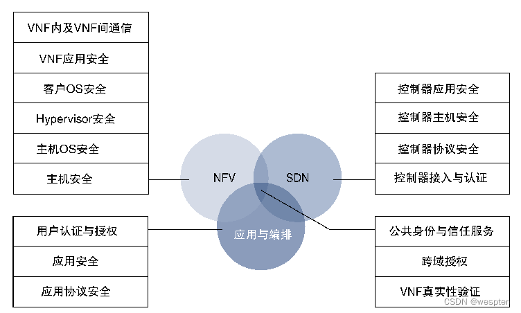
Some essential security measures are discussed next:
- Intra-VNF and inter-VNF communication: There are two paths for communication traffic between VNFs, one of which is inside the same server and uses a virtual link. Another path is between servers, using physical infrastructure. For these two situations, corresponding security measures need to be defined for internal and inter-VNF communication to ensure traffic security.
- NFV infrastructure: The host OS (Operating System, operating system), Hypervisor, firmware, and BIOS security patches need to be updated in a timely manner to plug security vulnerabilities in the infrastructure. It is necessary to strengthen security prevention and control of external infrastructure access behaviors to prevent TCP (Transmission Control Protocol, Transmission Control Protocol) synchronous attacks, large-traffic DDoS (Distributed Denial of Service, distributed denial of service) and other attacks.
- SDN protocol security: The traffic from the SDN controller to the NFV infrastructure needs to be secured. Appropriate security measures must be taken to deploy secure encryption and authorization policies. For example, although OpenFlow does not mandate security as a required field, using TLS (Transport Layer Security, Transport Layer Security) mode can provide device authentication measures for switches or end-device access controllers, and can also be encrypted in an encrypted format. Protects control protocol messages between controllers and switches to prevent eavesdropping and man-in-the-middle attacks.
- SDN controller security: Since SDN is an application program running in a host or VM (Virtual Machine, virtual machine) environment, the security measures described in NFV infrastructure can be used to strengthen the security of the host or VM. For SDN applications, it is necessary to assess the vulnerability of these applications and take appropriate security measures. Taking the ODL (Open Daylight) controller as an example, since the controller is a Java-based application, all security holes in Java must be evaluated and patched, so as to ensure that the ODL controller is free from attacks.
- User and administrator authorization policies: User and administrator authorization policies must be defined for a multi-domain architecture consisting of computing infrastructure, VNFs, orchestrators, SDN components, hypervisors, and applications, each of which may belong to Different administrative or operational groups. If the NFV infrastructure needs to host tenant-based networks for customers, then the authentication and authorization operations for these tenants must be consolidated to provide the necessary security to meet the customer's access policies.
- Common security policy: Due to the close interaction between multiple domains, a single user may need to access multiple domains with different permissions. As a result, security policies must be adapted to this flexibility, such as SSO (Single-Sign-On, single sign-on) identity authentication and auditing.
3. Implementation of virtualized network functions
Traffic in a network may need to go through a series of network functions as it enters, traverses, and leaves the network. These network functions may vary due to a number of design factors related to traffic. It is regarded as a chain of functions linked together, and the network services formed by these network functions are displayed through the combined effect of these network functions, so the design pattern of arranging the data packet path to traverse these network functions in a specific order is called Service function chaining, or service chaining for short.
In order to reflect the forwarding path, a similar line graph in the figure below is usually called a network forwarding graph.
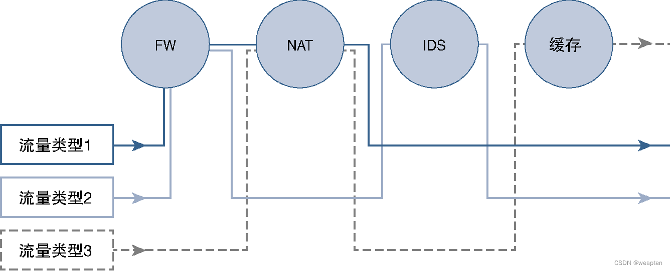
Previously, the concept of service chain was introduced by taking the mobile network as an example. Here, the definition and implementation of service chain architecture and related standards in NFV scenarios are introduced.
1. Service Chaining in Traditional Networks
Service chaining is not a new concept. Traditional networks have implemented service function chains through the physical and logical connections of network devices. However, traditional networks are very rigid. If you want to make any changes to paths based on traffic categories, or add (delete) Any new network function block must change the service chain, which is extremely challenging in practical applications.
If new network functionality requires the addition of new hardware, it takes a lot of time and resources to install the physical equipment and configure the transmission links. Another possible approach is to use an overlay network, especially when hardware resources already exist, by configuring the overlay network to reroute the service path, thereby adding the required functional blocks. While an overlay network can address some of the physical network limitations of service chaining, it also increases configuration complexity and still depends on the underlying network topology.
The following figure is an example. Two types of traffic are configured for different service chains using Layer 2 VLANs. No matter what method is used to add new network functions, new services cannot be deployed during network operation.
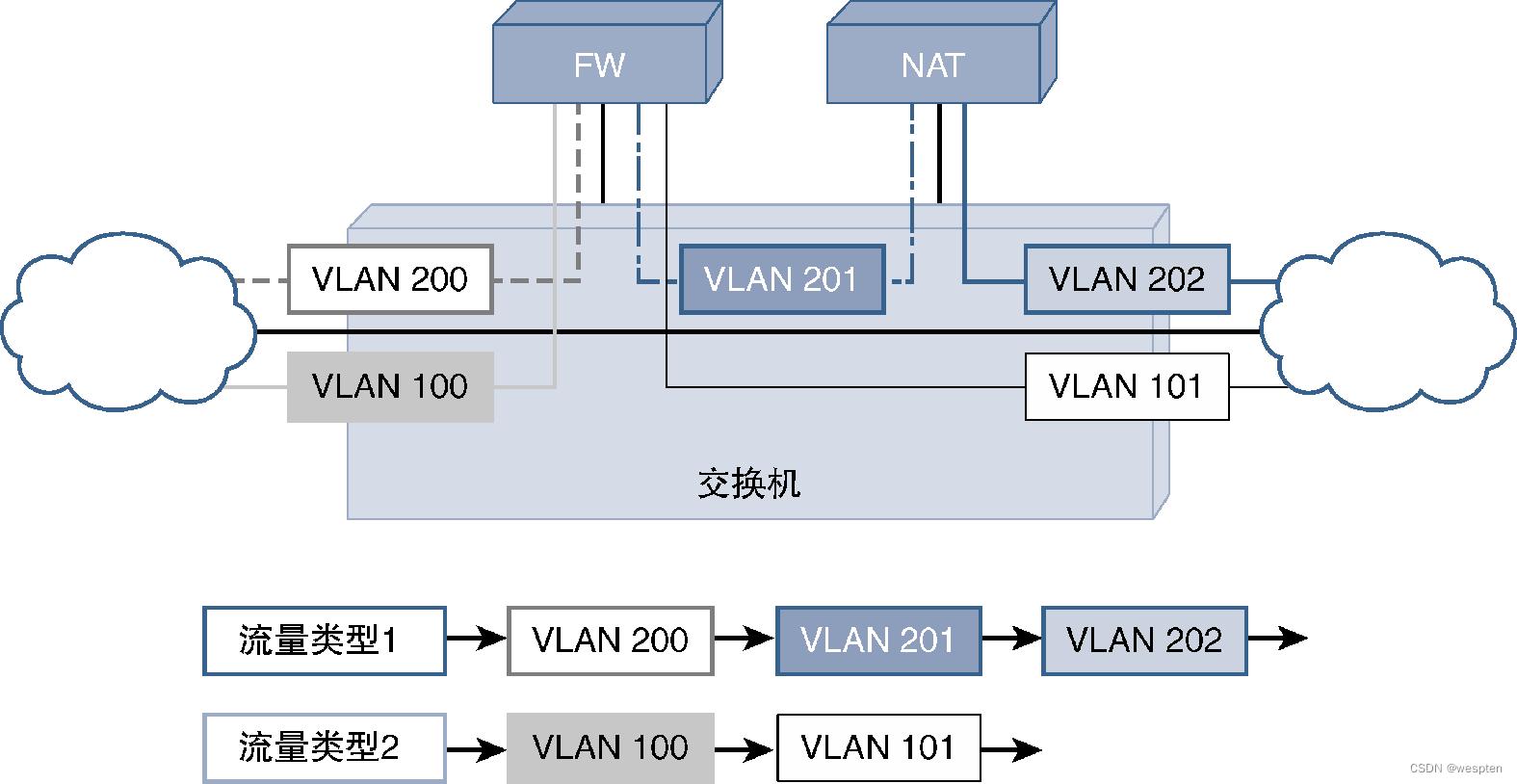
Doing so not only results in lost revenue, but also places severe constraints on the scale of cloud service deployments that vendors hope to meet in a faster and more flexible manner.
There is another challenge in using physical or overlay network technology to implement service chaining, that is, it cannot provide application-level granularity, support all transmission media, or realize the interconnection of different overlay networks. Paths (intermediate nodes or end nodes can use the data path to influence packet processing decisions) carry information at the application level.
2. Service function chain to meet cloud expansion requirements
For an agile and flexible network architecture that can adapt to business changes in a shorter period of time to meet market needs, an SFC (Service Function Chaining) architecture that can support new services is required, and these services must be able to be inserted dynamically, and Minimal or no disruption to existing networks. Given that the industry is moving toward virtualization, the architecture must also be able to do so across virtual, physical or hybrid networks.
In addition, service function chaining technology also needs to carry information from applications and be able to parse them. Some standards and use cases have emerged to meet the above needs, and these standards and use cases are discussed in detail below.
In order to realize the service chain function meeting the above target requirements in a unified and compatible way in the whole network, IETF (Internet Engineering Task Force, Internet Engineering Task Force) has been trying to define a service chain architecture, defined in the architecture With a variety of functional modules, the service chain realized in the case of cooperative work can well meet the cloud expansion requirements and the aforementioned goals.
The following diagram gives a high-level view of the architecture and the related components:

Each functional module shown in the figure is a logical functional module, and some or all of the functions may be performed by a single physical device, a virtual device, or a hybrid device. The specific functions of these components will be introduced in detail below.
1) SFC domain
If the network supports the end-to-end service function chain function and is located under a single management domain, then the SFC architecture refers to the network as an SFC-enabled domain (or SFC domain for short). An SFC domain has entry nodes and exit nodes, which form the boundaries of the SFC domain. After the data packet enters the SFC domain, the SFC will classify it and guide it to the correct network function. When the data packet leaves the exit node, it will delete all the information related to the SFC, and then forward it to the external network.
Therefore, the SFC domain is only a part of the entire network, used to perform network functions related to specific services, and has a corresponding control mechanism that can select traffic that needs to traverse these network functions according to rules.
2) Classifier
The definition of the classifier is very simple and intuitive, which is to classify the data entering the SFC domain. The traffic classification operation can be based on the source end or the destination end very simply, and a very complicated classification policy can also be defined. The classifier will add the SFC header to the data packet to ensure that the traffic can be transmitted along the correct path in the network according to the classification rules (such as service policy or other matching conditions).
Like all policies, the policies mentioned here are also a set of rules, consisting of matching conditions and matching actions. The policy in the SFC scenario can match the information in the network layer, and then decide which group of network functions should be performed on the data packet according to the matching situation. Since matching rules can also match application layer information, the traffic path determination mechanism of SFC is very flexible and fine-grained.
3) Service Function (SF)
SF (Service Function, service function) is a logical function module that performs network services or network functions on data packets. SF can interact with the application layer or the layers below, and can include various services such as firewall, DPI (Deep Packet Inspection, deep packet inspection), cache or load balancing.
Ideally, the device performing the service function supports SFC, which means it can understand and process the SFC header. However, the SFC architecture also allows SFs that do not support SFC, that is, the SF cannot process data packets carrying SFC information. In this case, it is necessary to use the Service Function Proxy (Service Function Proxy) to process the SFC data that enters and exits the SF that does not support the SFC function. Bag.
4) Service Function Path (SFP)
SFP (Service Function Path, Service Function Path) is specification information that defines classified traffic paths in the SFC domain. Taking urban bus lines as an example, if passengers take a bus heading for a specific route, they will pass through the exact station and route. Passengers can also get off at a station in the middle according to their needs, and then take a connecting journey on a different line bus.
Similarly, SFC is not a linear chain that strictly defines all hops, but only some hops can be defined, and traffic can be flexibly adjusted to new traffic paths as needed.
The following diagram graphically explains the concept of an SFC path:

5) Service Function Chaining or Service Chaining (SFC)
SFC is a logical abstraction about the complete topology of network services and the parameters or constraints associated with the traffic path. Therefore, SFC is not a logical functional module, but a unified view of logical functional modules such as SFP, SF, and SFC domains. . Still taking the previous bus lines as an example, SFC can be regarded as all bus stations and bus line operation diagrams in all areas of the city, while SFP is one of the bus lines.
6) Service function chain encapsulation
After the classifier identifies the traffic that needs to be forwarded to the service chain path, it will add additional header information to the data frame. This additional header is the service function chain encapsulation. At present, there are many possible encapsulation headers, and overlay network technologies such as Layer 3 VPN and SR (Segment Routing, segment routing) can realize the service chain encapsulation function.
These overlay technologies all rely on the existence of the IP network. IETF is promoting the standardization of the new SFC encapsulation format based on NSH (Network Service Header), which can work with various underlying networks. Have
7) Reclassification and forking
The marking action of the classifier on the SF header is based on the information available when the packet enters the SF domain, although some up-to-date information about the packet (especially based on the SF in the path) may require the path to be modified and the traffic to be diverted on other paths, At this time, the intermediate service function is used to reclassify the data packets, and then update or modify the SF path.
This information results in updating the information embedded in the packet, or updating the packet's SF header, or both. We refer to this SFP update that leads to a new path as branching. For example, if the rules of the firewall SF require that traffic originating at a certain time of day cannot go to the game server, then this traffic will be sent to the parental control function.
8) Service Function Forwarder (SFF)
SFF (Service Function Forwarder) is responsible for viewing the SF header and determining the forwarding method of the data packet carrying the service header, so as to ensure that the data packet can traverse the specified network service. After the data packet is processed by the service function, it will be sent back to the SFF, and the SFF will forward the data packet to the next network service. Like other functional modules, SFF is also a logical unit that can reside within the service function or on an external ToR (Top of Rack, Top of Rack) switch.
One SF domain can have multiple SFFs. The following figure is a schematic diagram of the operation of the SFF function.

The SFF in the figure sends two different types of classified traffic to different SFs, and the SFs return them to the SFFs after processing them. Similar goals have been achieved by using VLAN (Virtual LAN, virtual LAN) overlay technology before, but for this case (that is, the work to be done by the service chain), the configuration process is very complicated and difficult to track, we only need to use the SFC architecture and use Classifier, SF header, and SFF can easily achieve the above goals.
9) Service Function Proxy (SF Proxy)
If the network service cannot handle the service function chaining information, then simply placing the SF proxy in the traffic path to and from the service function ensures that the SF is still part of the SF domain.
The SF agent will delete the service function header, and then send the decapsulated traffic to the service function according to the SFC header information, and then send the data packet back to the SF agent after processing the service, and the SF agent will reinsert the service function header and path information, And forward the traffic to SFF for subsequent operations.
The disadvantage of this method is that the service function can only perform local network functions, but cannot perform any operations that may affect subsequent SF path changes.
10) Service function control plane
The service function path is constructed by the service function control plane responsible for the service overlay path. This overlay path can be a fixed path that provides a static flow for data packets, or a dynamic path based on network deployment characteristics, or a static path and a dynamic path. The combination. The service function control plane supports a distributed model and a centralized model, and the centralized controller in the centralized model is called a service function controller.
11) Service function controller
The concept of SDN is very suitable for SFC, which can define service paths in a centralized controller to abstract network information and apply policies through the application layer and centralized control functions. The logic module that realizes this function is called a service function controller.
For networks supporting SDN, the SF controller can be integrated with the SDN controller.
3. Network Services Header (NSH)
NSH (Network Service Header, Network Service Header) provides a protocol standard for SFC encapsulation, which is managed by the IETF and supported by a large number of suppliers. NSH mainly includes two components: the first component is responsible for providing information about the service path adopted by the traffic flow in the network, and the second component carries additional information related to the payload in the form of metadata. Applications and higher-level protocols can utilize NSH's metadata component to send information along the service path that is useful for the service path selection decision process and for other special processing that may need to be performed on packets.
The NSH protocol header includes three parts: basic header, service path header, and context header, as shown in the figure below.
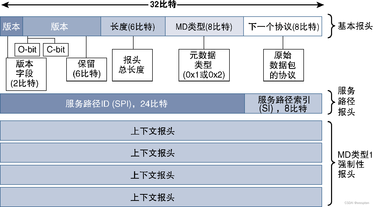
1) Basic header
The basic header is a 4-byte header containing the following fields.
- The 2-bit version field is reserved for backward compatibility with future versions.
- A 1-bit O-bit field, which indicates whether the data packet contains O&M (Operational and Maintenance, operation and maintenance) information. If the O-bit in the NSH header is set, then the payload of the packet should be checked by SF and SFF.
- 1-bit C-bit field, which indicates that there is at least one TLV (Type-Length-Value, Type-Length-Value) containing key information in the latter part of the header. The purpose of this bit is to simplify the data packet parsing program or hardware. Just simply check whether the C-bit is set (without parsing TLV data) to determine whether there is key TLV information.
- 6-bit field, reserved for future use. The 6-bit length field indicates the length of the NSH header.
- 8-bit field field, reserved field. Used to define the metadata type or options used. Currently NSH defines two types of metadata: Type 1 and Type 2. The header format of NSH type 1 metadata is fixed, which helps service forwarding operations to maintain predictable forwarding performance, and also facilitates optimal implementation of hardware. All NSH implementations must support this type of metadata. The second option is Type 2 metadata. Type 2 metadata is of variable length and can carry custom information, such as application-level listeners, TLV, etc. The protocol expects NSH implementations to support Type 2 metadata. The basic header information only identifies the metadata type, and the content about the metadata information itself is located in other header fields.
- The last 8 bits of the basic header are used to identify the original protocol of the packet.
The allowed inner packet protocol values for the protocol are shown in the following table:

2) Service path header
The service path header contains information about the service path, and is a 4-byte header, including the following fields.
- The SPI (Service Path Identifier, service path identifier) field is the main part of the header, using 24 bits of the 32 bits. The SPI uniquely identifies the service path that the packet will use within the SFC domain. If the service function path is explained by taking the bus line as an example, then the SPI is the line number of the bus.
- The SI (Service Index, service index) field uses the remaining 8 bits to indicate the position of the data packet in the service path. Every time a data packet passes through a node with the SFC function enabled, the service path will be decremented by 1, so the SF where the data packet is located can be accurately determined by checking the SPI and SI values. SI works similarly to the TTL (Time To Live) value in the IP header to detect loops.
3) Context header
The context header contains metadata and other information embedded by or based on higher-level information. The length of this header depends on whether the metadata used is type 1 or type 2. If type 1 metadata is used, then four 4-byte context header blocks will be added to the NSH header; if type 2 metadata is used data, the header can be of variable length or not exist at all.
4) NSH MD type
As described in the basic header, the NSH header supports two different MD (MetaData, metadata) options, and the context header will also change with the type of MD. For type 1, the data in the context header is opaque and has no specific format, and the data contained in the 4 fields can be any metadata the implementation chooses. The NSH standard recommends but does not require the use of the following 4 context header fields.
- Network platform context: information about network devices, such as port speed and type, QoS (Quality of Service, quality of service) marking, etc.
- Network Shared Context: Data available to network nodes that will be useful when passed to other nodes in the network. For example, the information of the client associated with the interface, the location information of the node, and the like.
- Service Platform Context: Network service information that can be used by network nodes, which can be shared with other nodes. For example, the type of hashing algorithm used to load balance traffic.
- Shared Service Context: Contains metadata useful for implementing network services in the network. If special treatment is to be applied to traffic traversing the network (possibly based on the level of service the user has purchased), then this information can be embedded as metadata in headers that propagate to all NSH-enabled devices.
If a type 2 MD is used, then there can be any number of context headers (the length field of the basic header will be very useful in this case, because the length of the NSH header is variable in this case).
Unlike the mandatory Type 1 Context header, the NSH standard defines a specific format for the optional Type 2 header, as shown in the figure below.

TLV is an acronym for Type-Length-Value (Type-Length-Value), which is widely used in various network protocols. By definition, a TLV encapsulates data with a type field that acts as a key, a variable-length value field, and a length field that indicates the size of the value field. This is a general method of passing variable-length key-value (key-value) pairs of information through the protocol.
The TLV format is adopted, in which the type field is 8 bits, the length field is 5 bits, the value field is 32 bits, and the reserved field is 3 bits (for future use). In addition, a 2-byte TLV category (Class ) field, the role of the TLV category field is to specify the category of the TLV field, such as the standard information of the supplier to which the TLV belongs or the TLV implementation being used.
The value of the type field remains open and can be defined by the implementation of the specific NSH protocol, but its high-order bits have a certain special meaning. This bit indicates that the nodes that the data packet passes must process and understand the TLV. Therefore, it is mandatory for the SFC to understand TLVs with a value of 128 to 255 in the type field, and those with a value of 0 to 127 in the type field can be ignored.
The NSH header is located between the original Layer 2 or Layer 3 header and the data payload, as shown in the figure below.

In order to provide functions such as service visibility, service assurance, and troubleshooting, NSH provides O-bit in the header to support O&M functions.
The setting of the NSH service path can be distributed, and each network node can define the service path, or a centralized controller can be used to realize the centralized setting method, and the centralized controller with network viewing ability defines the service path, and through The classifier inserts the NSH service path into packets from the service domain.
5) Metadata
A major advantage of SFC is the ability to convey and use application-level information in the form of metadata. From the general definition of metadata, the term metadata refers to the set of information related to data. For SFC scenarios, metadata provides contextual information related to data traversing the SFC domain. The role of the SFC classifier is to insert metadata in service headers (such as NSH context headers), and SFC can extract this information from higher-level protocols (such as information in HTTP headers or URLs).
For example, a classifier can use metadata to tag video traffic according to different destinations, placing traffic destined for preferred streaming content on high-quality service paths. After the metadata is inserted into the SFC protocol header, the nodes in the path (SFF, SF, etc.) read, process and respond to the data and perform appropriate predefined actions.
Different methods can be used to exchange metadata information between components of the service function chain, and the common methods are as follows.
- In-band signaling, such as NSH, MPLS labels, and segment routing labels.
- Application layer headers, such as HTTP.
- Consistent out-of-band signaling, such as RSVP (Resource Reservation Protocol, resource reservation protocol).
- Inconsistent out-of-band signaling, such as OpenFlow and PCEP (Path Computation Element Protocol, Path Computation Element Protocol).
- Mixed in-band and out-of-band signaling, such as VXLAN (Virtual Extensible LAN, Virtual Extensible LAN).
- in-band signaling
If the metadata is carried in the packet as part of the packet, then it is called in-band signaling. The metadata at this time may be part of the header or part of the payload.
The figure below shows a schematic diagram of the metadata signaling flow. The web service header is a good example of in-band signaling.
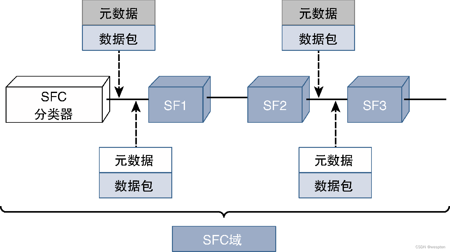
Metadata in the application layer header: the metadata in the application layer header can be transmitted in the application layer header, as long as the service function that can use the seven-layer information can use the information. Common use cases for application layer metadata include the HTTP <meta> tag and SMTP X metadata.
Consistent out-of-band signaling: If metadata information is carried in a separate channel and that data is transmitted in a different stream (even if both packet streams are on the same path), then it is consistent out-of-band signaling, as shown in the following figure Show.
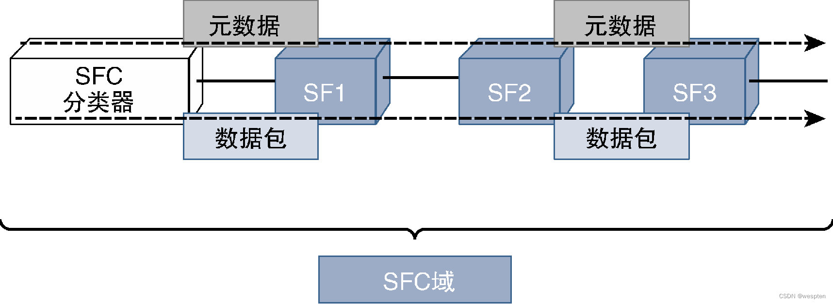
FTP (File Transfer Protocol, file transfer protocol) is a typical example of using this type of signaling, port 21 is used for control signaling, and port 22 is used for data transmission.
Non-consistent out-of-band meta-signaling, although the meta-data in the previous signaling mode is carried by other streams than the data stream, the paths of the two packet streams are still the same. For non-coherent out-of-band signaling, metadata signaling takes a different path than data traffic flow.
The signaling control plane in the signaling model example in the figure below interacts with nodes and is responsible for managing metadata. Common cases of using this type of signaling mainly include BGP (Border Gateway Protocol, Border Gateway Protocol), route reflector, PCEP, and OpenFlow.

Hybrid in-band and out-of-band signaling, the metadata signaling of the network may be mixed metadata signaling including in-band signaling and out-of-band signaling.
As can be seen from the figure below, the hybrid signaling model is a combination of the in-band model and the out-of-band model. Common cases of using this type of signaling include VXLAN and L2TP (Layer 2 Tunneling Protocol, Layer 2 Tunneling Protocol)
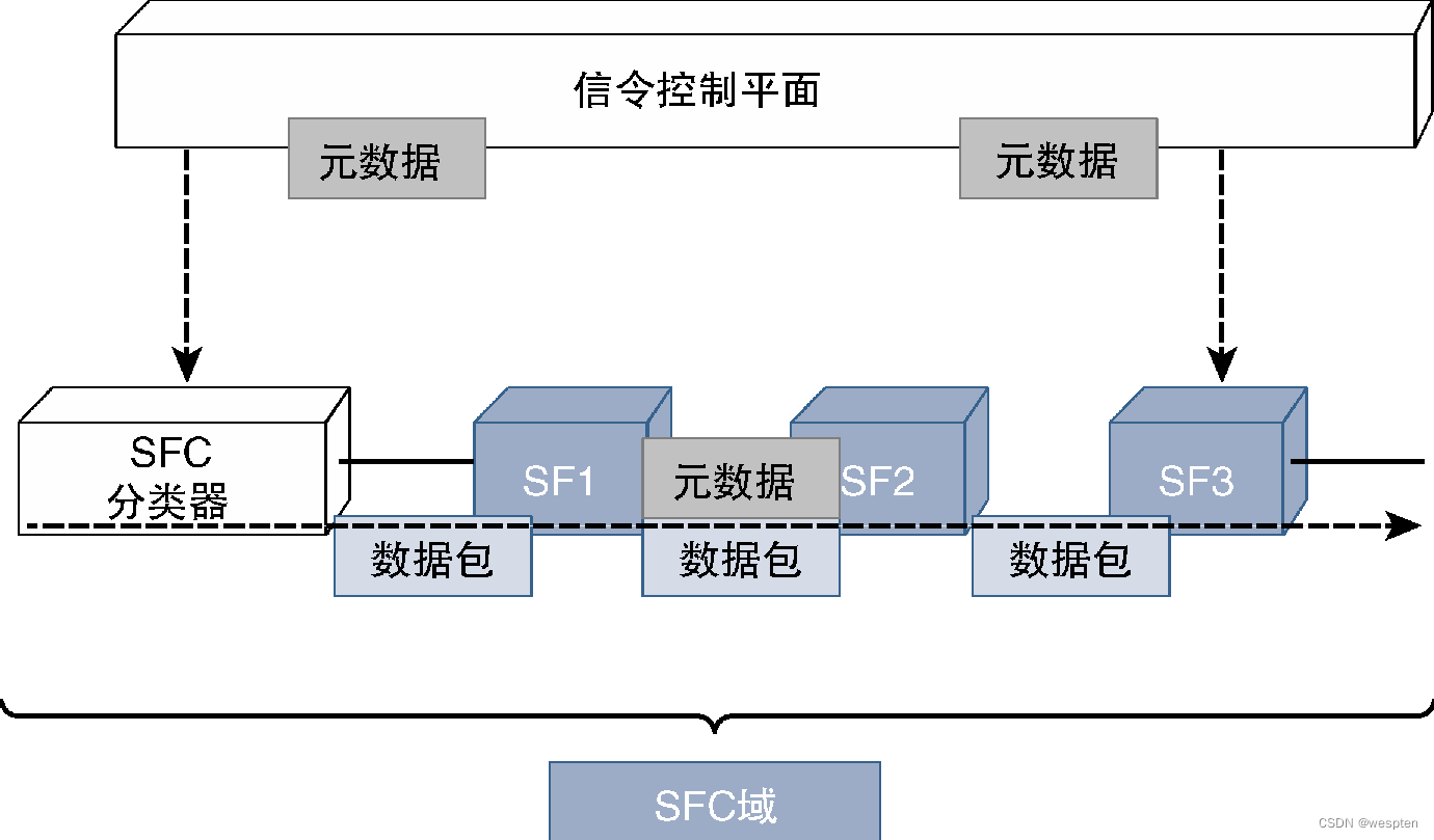
4. Other SFC protocols
Although NSH supported by the IETF is an emerging standard for SFC, metadata communication can be implemented in a variety of ways, so SFC can be implemented through a variety of protocols, including some protocols that have existed for a long time, such as MPLS-TE, VXLAN or SR -TE (Segment Routing Traffic Engineering, segment routing traffic engineering).
The figure below shows an example of implementing SFC with SR-TE, where the centralized SDN controller acts as SFC and communicates with devices in the network through PCEP.

The SFC classifier attaches the SR (Segment Routing, segment routing) label stack to the data packet according to the predefined policy based on the traffic type, and the traffic carrying the SR label will be directed to the device that performs the specified function (acting as SF) (according to outermost label). After the SF has processed the packet, it will be directed to the next hop according to the next SR label.
If the SFC controller determines that the processing operation of the SF requires recalculation of the path, it can instruct the SF to insert a new set of labels on the existing label stack.
5. Service Chaining Use Cases
The advantage of service chaining is that traffic paths can be controlled through traffic classification (based on high-level protocol information), and network designers, service providers, and end users can all benefit from it.
For network designers, the service chain provides a powerful flow control mechanism, which can realize complex and fine-grained application-aware policies, improve network usage efficiency, and thus well adapt to different times of the day, demand fluctuations, and network failures. Scenes.
Enterprises can use metadata information to provide users with very refined service levels and provide new innovative services. The possible applications are as follows.
- Video traffic from a home surveillance system can be classified and encrypted before it is sent to cloud storage or streamed remotely.
- It can provide network security services, divert browser traffic to DPI (Deep Packet Inspection, deep packet inspection) devices that can identify and warn of malware, and allow voice, video, and other data traffic to bypass DPI.
- Service providers can offer an optional solution for SD-WAN (Software-Defined Wide-Area Network). For SD-WAN solutions, enterprises need to implement their own SD-WAN solutions and use them for communication between different office locations to optimize WAN links. If an enterprise does not want to maintain its own SD-WAN solution, but wants to achieve the same effect, then it is possible for the service provider to classify the traffic through SFC and based on destination, source, application type and other metadata information Traffic is marked by which different service paths can be established for the traffic.
- End users can benefit from the new flexible services demonstrated in the above application examples. SFC, combined with NFV, also allows users to modify their service agreements as needed, utilizing service portals provided by service providers through which users can add, delete or modify network functions they wish to include in service packages.
The following takes the parental control Internet service as an example to analyze the way to create, design and deploy new services using the SFC concept.
- Requirement: The service should allow parents to restrict their children's access to the Internet from Internet-connected devices.
- Design: The browser of each device will send metadata identifying information such as OS version and hardware, and the browser can send additional metadata through plug-ins to simplify the identification of Internet devices to children's devices. Service providers design classifiers to use specific metadata matching strategies to mark the SFC header of traffic, and route traffic identified as originating from children's devices to the firewall, while traffic from other devices does not need to pass through the filtering device.
- Implementation: The service provider provides a service portal through which parents can specify time- and destination-aware filters and define device profiles that can be mapped to different service policies.
4. Programmability of virtualized network
In order to take full advantage of the technical advantages of NFV and SDN, it is necessary to maximize network programmability to configure, manage, and maintain the network. These technologies and the increasing popularity of open software architectures have laid a solid foundation for the realization of programmable networks.
For completeness, the following step-by-step describes how to exploit and leverage the programmability of a virtualized network during the deployment and operation phases of an NFV network.
First, it is assumed that the NFV infrastructure components (computing, storage, and network) and the underlying network providing connectivity have been deployed in place. The following figure shows the event flow in the application scenario of NFV, SDN, and application convergence. The steps listed in the figure are aimed at In explaining how the application is involved and the complete implementation steps.
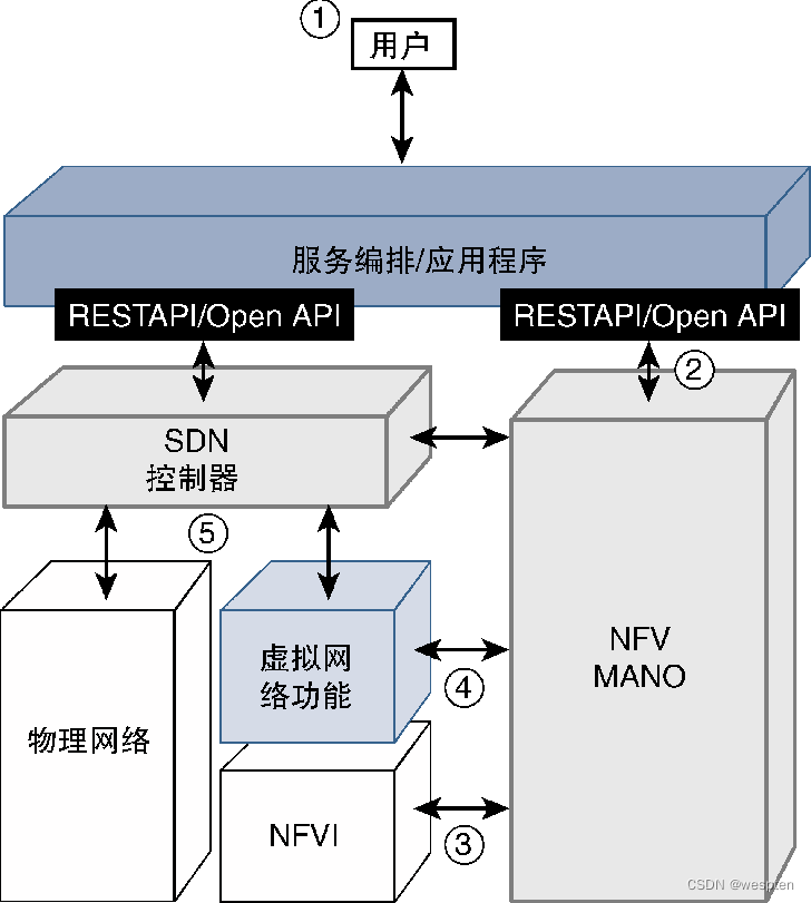
The detailed steps are as follows:
Step 1: Start the network design and implementation process from the application layer. The application layer is located at the top layer of the layered architecture and communicates with NFV-MANO and SDN controllers.
The application layer may consist of a single application, or it may consist of a set of independent applications that work together and take on the role of a service orchestrator, network monitoring and management system. The application program can be written in any language, as long as it can use the northbound protocol of MANO and SDN modules to communicate, generally using Python, C ++, Java and Go languages, and the northbound protocol is usually released by the developers of SDN and MANO tools REST API or Open API.
Step 2: According to the service description, the application communicates with MANO to instantiate the virtual machine and VNF required by the network service. Various functional modules of MANO, such as VIM and infrastructure can create virtual machines, and VNFM is responsible for creating VNF resources, etc. These modules communicate through the reference points defined by ETSI.
Step 3: After the VNFs are created, use VLD (Virtual Link Descriptor, virtual link descriptor) information to interconnect these VNFs. The interconnection of VNFs involves the programming of virtual switches.
Step 4: Once the VNFs are deployed and connected, it is time to create the topology for the virtual network services that make up the data plane of the network. The data plane can be a pure Layer 2 network, a VXLAN-based network, a Layer 3/IP-based network, or an MPLS-based network. At this point the network is ready to perform various functions such as firewall, load balancing, NAT, etc. While the network uses the actual physical network (which constitutes NFVI) as its underlay network, the network itself can also be used as the underlay network for the service layer (using service function chains to provide overlay services).
Step 5: The application at this point interacts with the SDN/SF controller and uses the controller to deploy the appropriate service path for the traffic according to the defined policies.
The SDN southbound protocol used for communication from the controller to the VNF is commonly used NETCONF, RESTCONF, and gRPC, and other protocols can also be used, such as XMPP, PCEP, OpenFlow, or Open API used by Juniper Contrail.
In this way, the initial deployment stage of the network is completed. At this time, the network layer can fully provide services, and the application program can also assume the role of network monitoring, and can monitor the network at different levels, such as monitoring the status of VNF and parameters related to functions, Monitor the status of VNFs and virtual machines, monitor infrastructure, and more. Applications can be programmed to make autonomous decisions based on information in monitoring data. Next, the following example will illustrate the benefits of doing so.
Traffic routing may need to be changed to handle a specific traffic flow, a surge in bandwidth demand, or a network failure. This decision to change traffic routing can be done by logic in the application and then passed to the device through the SDN controller.
NFV MANO can detect an increase in demand (anticipated demand or unexpected demand) that causes VNF resource overload, and then trigger the VNF’s resiliency mechanism based on this information. While these can be done through MANO's functional modules, these cases can also be handled by the application's decisions based on global policies.
Errors in VNF (or host) code can potentially impact the network. If applications can programmatically and intelligently identify and repair errors, then error conditions can be automatically repaired and the network restored or secured.
In addition, the application allows users, OSS/BSS (Operational and Business Support System, Operational and Business Support System), and other applications to interact with it and ask it to change network services, scale or topology. The application translates these requirements into explicit change requirements before sending instructions to MANO or SDN to implement those changes.
The above steps not only explain the role of applications and how programmability is used during network deployment and network operation, but also illustrate how networks are structured in multiple logical layers.
The diagram below details this logical layering concept and also shows the relationship between these topological layers and the 5 phases.
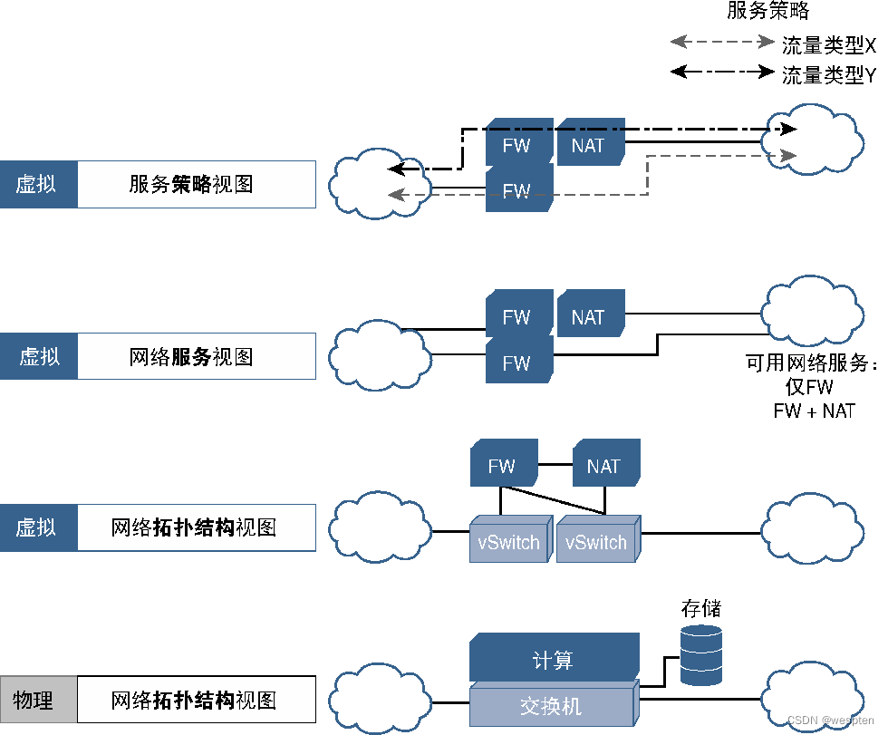
It can be seen from the figure that the physical infrastructure provides a topology view and serves as the original underlying network of NFV. The NFV network is created on top of the infrastructure and presents a virtual network topology view. This is a full-featured network, all VNFs are all interconnected in an expected topology to provide corresponding services. End users do not care about the interconnection method of VNFs, but only care about the content provided by the service, and the virtual network service view is displayed.
Finally, if SFC is deployed, the service topology is viewed as a logical network that provides traffic with a set of different services (based on traffic type, metadata, or other high-level information), implemented as traffic forwarding and processing policies, called Virtual Service Policy View.