One: get basic project template file
First we create a computer anywhere in a folder named "template to create a register", and then create two folders below it, as follows:
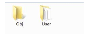
Obj folder: c storing compile a list of inventory produced / assembler / linker and debug information, hex files, preview information, package library and other documents.
User Folder: used to store user-written main.c, STM32F1 startup files, stm32f10x.h header files. We need to register the required basic engineering template file main.c, STM32F1 stm32f10x.h startup file and header files into the User folder.
After you copy the User folder in the file as follows:

Two: Create a project register
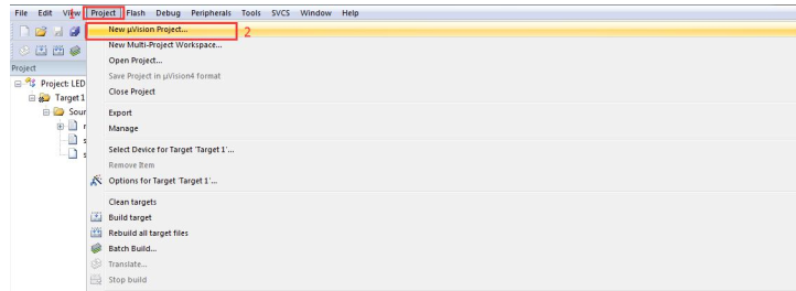
(1) Create a new project
Open KEIL5 software, create a new project, the project name according to your preference name, but be aware that the use of English, if a Chinese name some strange errors may occur, here we named Template, saved directly under the "Register template to create a" folder. Specific steps are as follows:
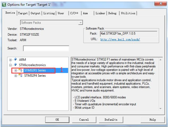
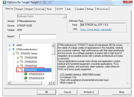
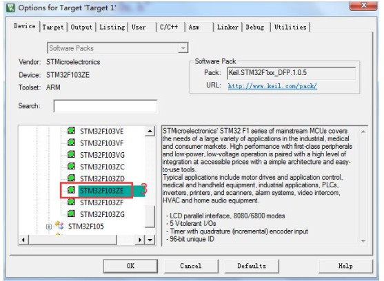
(2) Select the CPU model
The CPU based on the specific model you use to select a development board, we in the S & P PZ6806L and PZ6806D development board uses a chip STM32F103ZET6. If there is no CPU model you want, or do not have a model, then you certainly are not added when you install KEIL5 chip package software, KEIL5 comes KEIL4 not as many MCU models, KEIL5 need to add, specific operation is as follows:
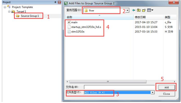
(3) add files to the project
Add in the new project file, the file from the "Register template to create a" folder under the acquisition, double-click the Group folder path of the file will be added, and then select the file. Steps are as follows:
(4) arranged Magic Wand
这一步的配置工作非常重要, 很多人自己编写程序编译后发现找不到 HE文件, 还有的人做后面 printf 实验时打印不出信息, 这些问题都是在这个地方没有配置好导致的。
(1) Target 中选中微库“Use MicroLib” , 主要是为了后面 printf 重定向输出使用。 其他的设置保持默认即可, 配置如下:

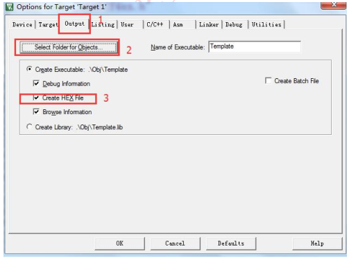
(2) Output 选项卡中把输出文件夹定位到我们工程目录下的 Obj 文件夹,如果想在编译的过程中生成 hex 文件, 那么那 Create HEX File 选项勾上。 配置如下:
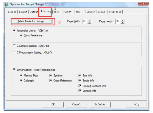
(3) Listing 选项卡中把输出文件夹也定位到我们工程目录下的 Obj 文件夹。 其他设置默认, 配置如下:
(4) ARM 仿真器配置
只有当你的仿真器安装好驱动并且连接了电脑和板子, 那么就可以开始配置。 如果使用我们公司的 ARM 仿真器可以直接插上电脑, 电脑会自动安装驱动无需手动安装, 而且将 ARM 仿真器的 USB 一端连接电脑, 另一端连接开发板上的JTAG 接口, 开发板即可供电, 只要在 KEIL 软件内进行相应的配置即可下载程序和仿真。 具体的配置如下(我们已经将 ARM 仿真器连接开发板) :
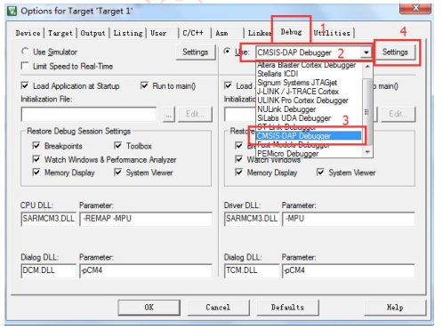
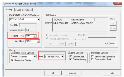
选择好 CMSIS-DAP Debugger 型号后点击 Settings, 会弹出如下界面, 如果你的型号没有选择错误的话, 自动会识别你的 ARM 仿真器 ID 了, 然后即可设置SW 或者 JTAG 模式以及复位的方式, 大家可以选择性使用 SW 或者 JTAG 模式。 如果使用 SW 模式的话, 必须勾选前面的 SWJ 复选框。 具体设置步骤如下:
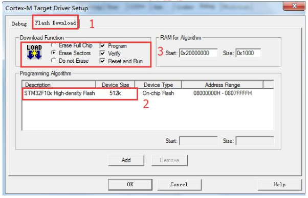
(5)芯片型号选择
同样在上一步的那个 Debug 选项卡内进行设置, 点击 Settings, 选择 FlashDownload 选项卡, 我们使用的芯片是 STM32F103ZET6,其 Flash 为 512K。 在框 3中的 Reset and Run 选项中, 如果勾上的话, 当程序下载进去后自动复位运行,如果不勾上, 程序下载进去后需按下开发板上复位键才能运行。 通常我们选择勾上。 具体配置如下:
最后点击 OK 按钮即可。然后进行编译, 编译后结果 0 错误 0 警告, 表明我们创建的寄存器模板完全正确。 如下:

到这一步我们的寄存器模板才算真正创建好。 在前面配置魔术棒时, 已经配置好了 ARM 仿真器, 将ARM 仿真器与开发板上的 JLINK/JTAG 接口连接好后,点击标号 1 即可将程序下载到开发板内。