1, briefly osi seven layer model and TCP / IP five layer model
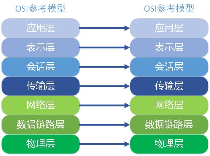
A, OSI reference model
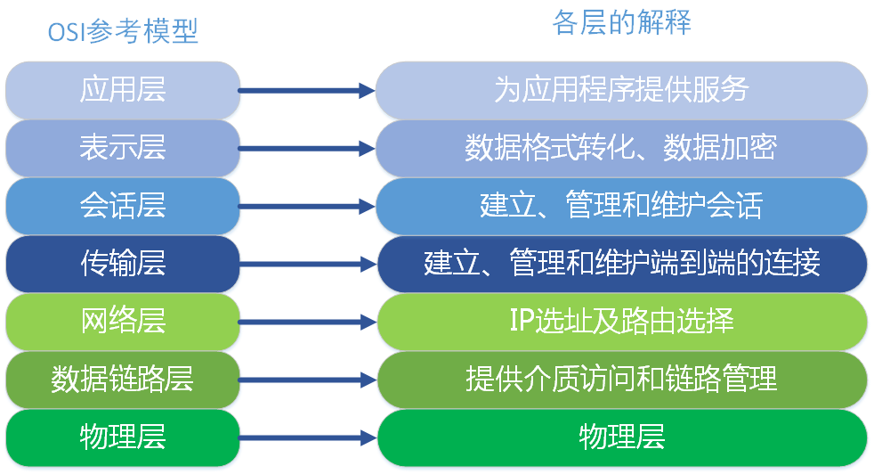
The data link layer is divided into two sublayers: a logical link control sublayer (LLC) sublayer and the media access control (MAC).
The MAC sublayer handles CSMA / CD algorithm, error checking data, framing and the like; LLC. Sublayer defines the last field enables to share a data link layer protocol. In actual use, LLC sublayer is not necessary.
This did not find the right example
<7> physical layer
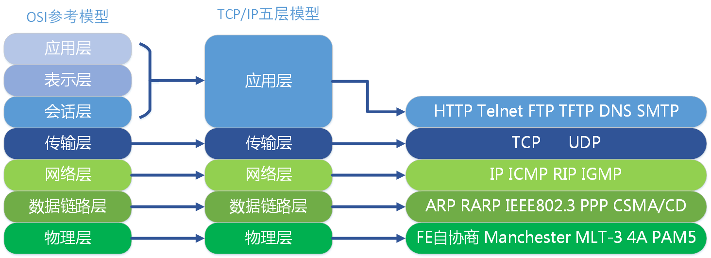
Two, TCP / IP five layer model


2, summary description of TCP three-way handshake fourth wave
Background Description
By introducing an IP layer on the network model, we know that the network layer, can achieve communication between two hosts. But this is not specific, because, really is an entity that communicates process in the host, a host is a process with a process to another host in the exchange of data.
Although the specific application can process IP protocol data packets to the destination host, but was not delivered to the host. The communication should be the end of the communication between the application process.
UDP, before transferring the data do not need to establish a connection, the remote host after receiving the UDP packets do not need to give any confirmation. Although UDP does not provide reliable delivery, but it is precisely because of this, and eliminating a lot of overhead, making it faster, such as some of the real-time requirements of the service, it is often using UDP. Application layer protocol corresponds mainly DNS, TFTP, DHCP, SNMP, NFS, etc.
TCP, connection-oriented service, you must first establish a connection, data transfer is complete to release the connection before transmitting data. Therefore, TCP is a reliable transport service, but precisely because of this, inevitably increased the number of overhead, such as confirmation and flow control. Corresponding to the application layer protocols include SMTP, TELNET, HTTP, FTP and the like.
Commonly known port number
| application | FTP | TFTP | TELNET | SMTP | DNS | HTTP | SSH | MYSQL |
|---|---|---|---|---|---|---|---|---|
| Well-known port | 21,20 | 69 | 23 | 25 | 53 | 80 | 22 | 3306 |
| Transport Layer | TCP | UDP | TCP | TCP | UDP | TCP | TCP | TCP |
TCP Overview
TCP connection as the most basic objects, each TCP connection has two end points, such breakpoints we call socket (socket), which is defined as the port number of the IP address that is spliced to form the socket, For example, if the IP address 192.3.4.16 and the port number is 80, then the socket is obtained 192.3.4.16:80.
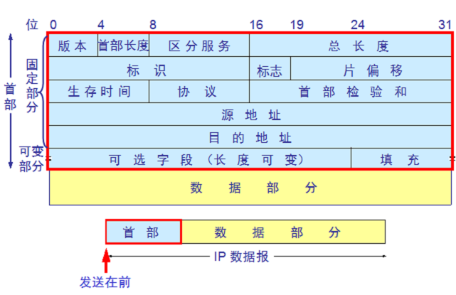
TCP packet header
1, the source and destination ports, each with 2 bytes are written into the source and destination ports;
2, the serial number, 4 bytes, the byte stream transmitted TCP connection in each byte are numbered sequentially. For example, the sequence number field value of the packet period is 301, and the data carried by the total of 100 fields, is clearly the next segment (if there is any) should start from the data number 401;
3, acknowledgment number, 4 bytes, it is desirable first data byte received counterpart next packet sequence number. For example, B received a packet sent from A, which is the sequence number field 501, and the data length is 200 bytes, B which indicates the correct receipt of data up to 700 A number transmitted. Thus, B expects to receive next data number A is 701, then B in acknowledgment sent to the A segment of the acknowledgment number is set to 701;
4, the offset data, four bits, it is noted that the TCP packet data at the start of how close the TCP segment;
5, reservations, accounting for 6, reserved for future use, but should have bit 0;
6, the URG emergency, when URG = 1, indicates that the urgent pointer field is valid. In this segment tells the system there is urgent data;
7, the ACK acknowledgment, only when ACK = 1, the acknowledgment number field is valid. TCP provides a connection is established in all the packets of the ACK transmission must be set to 1;
8, PSH push, when two interactive communication application process, the application process may wish to be able to receive an end of the other response immediately after typing a command, this time will PSH = 1;
9, the RST reset, when RST = 1, show serious error occurs in the TCP connection, the connection must be released, and then re-establish the connection;
10, sync SYN, when used to synchronize the serial connection is established. When SYN = 1, ACK = 0, indicates that the packet is a connection request, the connection if agreed, the response message should make SYN = 1, ACK = 1;
11, termination of the FIN, for releasing the connection. When FIN = 1, data indicating the sender of this message has been sent, and release requirements;
12, the window occupies 2 bytes, referring to notify the recipient, sending the newspaper text you need much space to accept;
13, and inspection, occupies 2 bytes, and header checksum data two portions;
14, urgent pointer, 2 bytes indicating the number of bytes of urgent data segment newspaper;
15, options, variable length, defined a number of other optional parameters.
TCP connection establishment (three-way handshake)
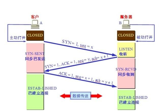
Note: The client and server are in the very beginning CLOSED state. Active open connection to the client, the server is passive open connection.
1, TCP server process to create a Transmission Control Block TCB, always ready to accept connection requests from the client process, the server at this time to enter the LISTEN (monitor) state;
2, TCP client process is to create a transmission control block the TCB, and then sent to the server connection request packet, which is the same portion of the header in the packet SYN = 1, while selecting an initial sequence number seq = x, In this case, TCP client end process enters the SYN-sENT (sent synchronous state) state. TCP predetermined, the SYN segment (SYN = 1 segment) can not carry data, but requires a number consumed.
3, TCP server receives a request message, if you agree connections, is a confirmation message. Confirmation message should ACK = 1, SYN = 1, confirmation number is ack = x + 1, but also to initiate a sequence number seq = y for themselves, this time, TCP server process into the SYN-RCVD (received synchronization )status. This message can not carry data, but also have to consume a number.
4, TCP client after receiving confirmation process, but also to give an acknowledgment to the server. Acknowledgment message ACK = 1, ack = y + 1, their sequence number seq = x + 1, In this case, TCP connection is established, the client enters the ESTABLISHED (connection established) state. TCP predetermined, the ACK segment may carry data, but does not carry data if the number is not consumed.
5、当服务器收到客户端的确认后也进入ESTABLISHED状态,此后双方就可以开始通信了。
为什么TCP客户端最后还要发送一次确认呢?
1、一句话,主要防止已经失效的连接请求报文突然又传送到了服务器,从而产生错误。
2、如果使用的是两次握手建立连接,假设有这样一种场景,客户端发送了第一个请求连接并且没有丢失,只是因为在网络结点中滞留的时间太长了,由于TCP的客户端迟迟没有收到确认报文,以为服务器没有收到,此时重新向服务器发送这条报文,此后客户端和服务器经过两次握手完成连接,传输数据,然后关闭连接。此时此前滞留的那一次请求连接,网络通畅了到达了服务器,这个报文本该是失效的,但是,两次握手的机制将会让客户端和服务器再次建立连接,这将导致不必要的错误和资源的浪费。
3、如果采用的是三次握手,就算是那一次失效的报文传送过来了,服务端接受到了那条失效报文并且回复了确认报文,但是客户端不会再次发出确认。由于服务器收不到确认,就知道客户端并没有请求连接。
TCP连接的释放(四次挥手)
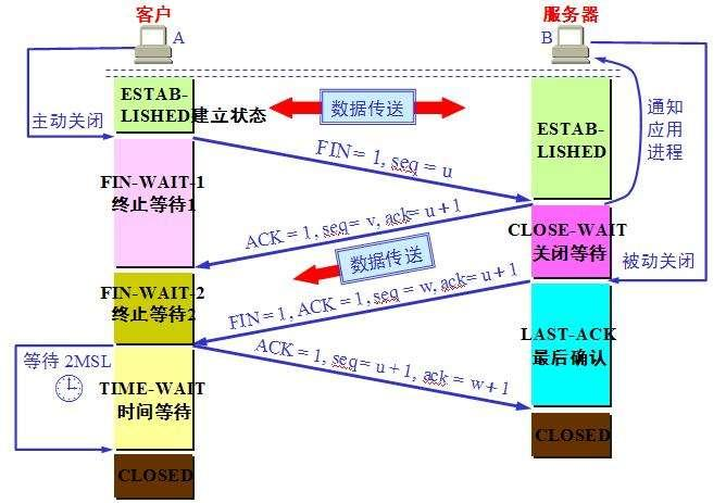
1、数据传输完毕后,双方都可释放连接。最开始的时候,客户端和服务器都是处于ESTABLISHED状态,然后客户端主动关闭,服务器被动关闭。
2、客户端进程发出连接释放报文,并且停止发送数据。释放数据报文首部,FIN=1,其序列号为seq=u(等于前面已经传送过来的数据的最后一个字节的序号加1),此时,客户端进入FIN-WAIT-1(终止等待1)状态。 TCP规定,FIN报文段即使不携带数据,也要消耗一个序号。
3、服务器收到连接释放报文,发出确认报文,ACK=1,ack=u+1,并且带上自己的序列号seq=v,此时,服务端就进入了CLOSE-WAIT(关闭等待)状态。TCP服务器通知高层的应用进程,客户端向服务器的方向就释放了,这时候处于半关闭状态,即客户端已经没有数据要发送了,但是服务器若发送数据,客户端依然要接受。这个状态还要持续一段时间,也就是整个CLOSE-WAIT状态持续的时间。
4、客户端收到服务器的确认请求后,此时,客户端就进入FIN-WAIT-2(终止等待2)状态,等待服务器发送连接释放报文(在这之前还需要接受服务器发送的最后的数据)。
服务器将最后的数据发送完毕后,就向客户端发送连接释放报文,FIN=1,ack=u+1,由于在半关闭状态,服务器很可能又发送了一些数据,假定此时的序列号为seq=w,此时,服务器就进入了LAST-ACK(最后确认)状态,等待客户端的确认。
5、客户端收到服务器的连接释放报文后,必须发出确认,ACK=1,ack=w+1,而自己的序列号是seq=u+1,此时,客户端就进入了TIME-WAIT(时间等待)状态。注意此时TCP连接还没有释放,必须经过2∗ *∗MSL(最长报文段寿命)的时间后,当客户端撤销相应的TCB后,才进入CLOSED状态。
6、服务器只要收到了客户端发出的确认,立即进入CLOSED状态。同样,撤销TCB后,就结束了这次的TCP连接。可以看到,服务器结束TCP连接的时间要比客户端早一些。
为什么客户端最后还要等待2MSL?
MSL(Maximum Segment Lifetime),TCP允许不同的实现可以设置不同的MSL值。
第一,保证客户端发送的最后一个ACK报文能够到达服务器,因为这个ACK报文可能丢失,站在服务器的角度看来,我已经发送了FIN+ACK报文请求断开了,客户端还没有给我回应,应该是我发送的请求断开报文它没有收到,于是服务器又会重新发送一次,而客户端就能在这个2MSL时间段内收到这个重传的报文,接着给出回应报文,并且会重启2MSL计时器。
第二,防止类似与“三次握手”中提到了的“已经失效的连接请求报文段”出现在本连接中。客户端发送完最后一个确认报文后,在这个2MSL时间中,就可以使本连接持续的时间内所产生的所有报文段都从网络中消失。这样新的连接中不会出现旧连接的请求报文。
为什么建立连接是三次握手,关闭连接确是四次挥手呢?
1、建立连接的时候, 服务器在LISTEN状态下,收到建立连接请求的SYN报文后,把ACK和SYN放在一个报文里发送给客户端。
2、而关闭连接时,服务器收到对方的FIN报文时,仅仅表示对方不再发送数据了但是还能接收数据,而自己也未必全部数据都发送给对方了,所以己方可以立即关闭,也可以发送一些数据给对方后,再发送FIN报文给对方来表示同意现在关闭连接,因此,己方ACK和FIN一般都会分开发送,从而导致多了一次。
如果已经建立了连接,但是客户端突然出现故障了怎么办?
TCP还设有一个保活计时器,显然,客户端如果出现故障,服务器不能一直等下去,白白浪费资源。服务器每收到一次客户端的请求后都会重新复位这个计时器,时间通常是设置为2小时,若两小时还没有收到客户端的任何数据,服务器就会发送一个探测报文段,以后每隔75秒发送一次。若一连发送10个探测报文仍然没反应,服务器就认为客户端出了故障,接着就关闭连接。
那么问题来了
为什么需要第三次握手?
第三次握手失败了怎么办?
三次握手有什么缺陷可以被黑客利用,用来对服务器进行攻击?
怎么防范这种攻击?
接下来进行一一解答。
1,为什么需要第三次握手?
答:如果没有第三次握手,可能会出现如下情况:
如果只有两次握手,那么server收到了client的SYN=1的请求连接数据包之后,便会分配资源并且向client发送一个确认位ACK回复数据包。
那么,如果在client与server建立连接的过程中,由于网络不顺畅等原因造成的通信链路中存在着残留数据包,即client向server发送的请求建立连接的数据包由于数据链路的拥塞或者质量不佳导致该连接请求数据包仍然在网络的链路中,这些残留数据包会造成如下危害危害:当client与server建立连接,数据发送完毕并且关闭TCP连接之后,如果链路中的残留数据包才到达server,那么server就会认为client重新发送了一次连接申请,便会回复ACK包并且分配资源。并且一直等待client发送数据,这就会造成server的资源浪费。
2,第三次握手失败了怎么办?
答:当client与server的第三次握手失败了之后,即client发送至server的确认建立连接报文段未能到达server,server在等待client回复ACK的过程中超时了,那么server会向client发送一个RTS报文段并进入关闭状态,即:并不等待client第三次握手的ACK包重传,直接关闭连接请求,这主要是为了防止泛洪攻击,即坏人伪造许多IP向server发送连接请求,从而将server的未连接队列塞满,浪费server的资源。
3,三次握手有什么缺陷可以被黑客利用,用来对服务器进行攻击?
答:黑客仿造IP大量的向server发送TCP连接请求报文包,从而将server的半连接队列(上文所说的未连接队列,即server收到连接请求SYN之后将client加入半连接队列中)占满,从而使得server拒绝其他正常的连接请求。即拒绝服务攻击
怎么防范这种攻击?
1,缩短服务器接收客户端SYN报文之后的等待连接时间,即SYN timeout时间,也就是server接收到SYN报文段,到最后放弃此连接请求的超时时间,将SYN timeout设置的更低,便可以成倍的减少server的负荷,但是过低的SYN timeout可能会影响正常的TCP连接的建立,一旦网络不通畅便可能导致client连接请求失败
4,SYN cookie + SYN proxy 无缝集成(较好的解决方案)
SYN cookie:当server接收到client的SYN之后,不立即分配资源,而是根据client发送过来的SYN包计算出一个cookie值,这个cookie值用来存储server返回给client的SYN+ACK数据包中的初始序列号,当client返回第三次握手的ACK包之后进行校验,如果校验成功则server分配资源,建立连接。
SYN proxy代理,作为server与client连接的代理,代替server与client建立三次握手的连接,同时SYN proxy与client建立好了三次握手连接之后,确保是正常的TCP连接,而不是TCP泛洪攻击,那么SYN proxy就与server建立三次握手连接,作为代理(网关?)来连通client与server。(类似VPN了解一下。)
5,为什么要四次挥手
答:前两次挥手是为了断开client至server的连接,后两次挥手是为了断开server至client的连接,如果没有第四次挥手,会出现如下状况:
server发送FIN数据包并携带ACK至client之后直接断开连接,如果client没有收到这个FIN数据包,那么client会一直处于等待关闭状态,这是为了确保TCP协议是面向连接安全有保证锝。
上面解释了为什么不是三次挥手,同理,两次挥手也是不安全的。不能保证server与client都能正确关闭连接释放资源,而不会造成资源浪费。
6,四次挥手之后client为什么还要等待2MSL的时间才释放资源关闭连接?
答:
如果client第四次挥手的确认报文段没有被server接收,那么server便会重发第三次挥手的FIN报文段,因此client要停留2MSL的时长来处理可能会重复收到的报文段。
让之前建立的client-server通信过程中或者是挥手过程中由于网络不通畅产生的滞留报文段失效。如果不等待2MSL,那么建立新连接之后,可能会收到上一次连接的旧报文段,可能会造成混乱。
3、描述TCP和UDP区别
TCP的优点: 可靠,稳定 TCP的可靠体现在TCP在传递数据之前,会有三次握手来建立连接,而且在数据传递时,有确认、窗口、重传、拥塞控制机制,在数据传完后,还会断开连接用来节约系统资源。
TCP的缺点: 慢,效率低,占用系统资源高,易被攻击 TCP在传递数据之前,要先建连接,这会消耗时间,而且在数据传递时,确认机制、重传机制、拥塞控制机制等都会消耗大量的时间,而且要在每台设备上维护所有的传输连接,事实上,每个连接都会占用系统的CPU、内存等硬件资源。 而且,因为TCP有确认机制、三次握手机制,这些也导致TCP容易被人利用,实现DOS、DDOS、CC等攻击。
工作在传输层
面向连接协议
全双工协议
半关闭
错误检查
将数据打包成段,排序
确认机制
数据恢复,重传
流量控制,滑动窗口
拥塞控制,慢启动和拥塞避免算法
UDP的优点: 快,比TCP稍安全 UDP没有TCP的握手、确认、窗口、重传、拥塞控制等机制,UDP是一个无状态的传输协议,所以它在传递数据时非常快。没有TCP的这些机制,UDP较TCP被攻击者利用的漏洞就要少一些。但UDP也是无法避免攻击的,比如:UDP Flood攻击……
UDP的缺点: 不可靠,不稳定 因为UDP没有TCP那些可靠的机制,在数据传递时,如果网络质量不好,就会很容易丢包。 基于上面的优缺点,那么: 什么时候应该使用TCP: 当对网络通讯质量有要求的时候,比如:整个数据要准确无误的传递给对方,这往往用于一些要求可靠的应用,比如HTTP、HTTPS、FTP等传输文件的协议,POP、SMTP等邮件传输的协议。 在日常生活中,常见使用TCP协议的应用如下: 浏览器,用的HTTP FlashFXP,用的FTP Outlook,用的POP、SMTP Putty,用的Telnet、SSH QQ文件传输 ………… 什么时候应该使用UDP: 当对网络通讯质量要求不高的时候,要求网络通讯速度能尽量的快,这时就可以使用UDP。 比如,日常生活中,常见使用UDP协议的应用如下: QQ语音 QQ视频 TFTP ……
有些应用场景对可靠性要求不高会用到UPD,比如长视频,要求速率
工作在传输层
提供不可靠的网络访问
非面向连接协议
有限的错误检查
传输性能高
无数据恢复特性
TCP与UDP区别总结:
1、TCP面向连接(如打电话要先拨号建立连接);UDP是无连接的,即发送数据之前不需要建立连接
2、TCP提供可靠的服务。也就是说,通过TCP连接传送的数据,无差错,不丢失,不重复,且按序到达;UDP尽最大努力交付,即不保   证可靠交付
3、TCP面向字节流,实际上是TCP把数据看成一连串无结构的字节流;UDP是面向报文的
   UDP没有拥塞控制,因此网络出现拥塞不会使源主机的发送速率降低(对实时应用很有用,如IP电话,实时视频会议等)
4、每一条TCP连接只能是点到点的;UDP支持一对一,一对多,多对一和多对多的交互通信
5、TCP首部开销20字节;UDP的首部开销小,只有8个字节
6、TCP的逻辑通信信道是全双工的可靠信道,UDP则是不可靠信道
4、总结ip分类以及每个分类可以分配的IP数量
我们知道在互联网上,如果想要被其他终端访问,就需要给每台主机(或路由器)的每一个接口分配一个在全世界范围内是唯一的标识符,这就是我们所说的唯一的IP地址。IP协议就是使用这个地址在主机之间传递信息,这是Internet能够运行的基础。
注意:由于现在我们依然使用的是IPv4地址,以下介绍内容以IPv4为基础。
ip地址
一、什么是ip地址?
简介( IPv4):
IPv4地址由四段组成,每个字段是一个字节,即4个字节、每个字节有8位, 最大值是255(=256:0~255)。 全世界范围是唯一的
32 位(4个字节 * 8位)的标识符。 IP地址由两部分组成,即网络地址和主机地址,二者是主从关系:

网络号 net-id,它标志主机(或路由器)所连接到的网络,网络地址表示其属于互联网的哪一个网络
主机号 host-id,它标志该主机(或路由器),主机地址表示其属于该网络中的哪一台主机。
两级的 IP 地址可以记为: IP 地址 ::= { <网络号>, <主机号>} 简而言之就是:IP地址 = 网络号+主机号
二、我们先来简单看一下互联网如何通过ip地址访问的?这个过程是怎样的呢?
通过路由器,路由设备当中有一张路由表,该路由表记录了所有ip地址的位置,这样就可以进行包的转发了,如果我们不区分网络地址,那么这张路由表当中就要保存有所有IP地址的方向,这张路由表就会很大,所以我们的ip地址由网络号和主机号组成。
如果不分网络号和主机号呢?
不区分的话,那路由器的路由表就都是32位地址,这样一来路由器维护的路由表会很大,转发速度会变慢(因为查询变慢)。而且为了终端可以相互访问,所有的路由器就要求要有全Internet的地址,所有人的路由器都要有足够的内存来存下全网地址。这样的建造成本会是现在的几千几万倍,甚至更高,估计路由器都买不起了。所以有了网络地址,就可以限定拥有相同网络地址的终端都在同一个范围内,那么路由表只需要维护这个网络地址的方向,就可以找到相应的终端了。既降低了成本又简化了过程,前人真是太聪明了啊。
ip地址分类
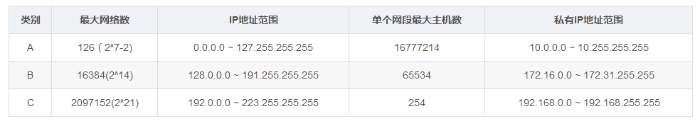
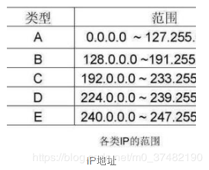
IP地址编址方案:IP地址编址方案将IP地址空间划分为A、B、C、D、E五类,其中A、B、C是基本类,D、E类作为多播和保留使用。
其中A、B、C3类(如下表格)由InternetNIC在全球范围内统一分配,D、E类为特殊地址。
A类地址
一个A类IP地址是指, 在IP地址的四段号码中,第一段号码为网络号码,剩下的三段号码为本地计算机的号码。如果用二进制表示IP地址的话,A类IP地址就由1字节的网络地址和3字节主机地址组成,网络地址的最高位必须是“0”。A类IP地址中网络的标识长度为8位,主机标识的长度为24位,A类网络地址数量较少,有126个网络,每个网络可以容纳主机数达1600多万台。
A类IP地址 地址范围1.0.0.0到127.255.255.255 (二进制表示为:00000001 00000000 00000000 00000000 - 01111111 11111111 11111111 11111111)。最后一个是广播地址。
A:0-127,其中0代表任何地址,127为回环测试地址,因此,A类ip地址的实际范围是1-126.
A类IP地址的默认子网掩码为255.0.0.0,每个网络支持的最大主机数为256的3次方-2=16777214台。
B类地址
一个B类IP地址是指,在IP地址的四段号码中,前两段号码为网络号码。如果用二进制表示IP地址的话,B类IP地址就由2字节的网络地址和2字节主机地址组成,网络地址的最高位必须是“10”。B类IP地址中网络的标识长度为16位,主机标识的长度为16位,B类网络地址适用于中等规模的网络,有16384个网络,每个网络所能容纳的计算机数为6万多台。
B类IP地址地址范围128.0.0.0-191.255.255.255(二进制表示为:10000000 00000000 00000000 00000000----10111111 11111111 11111111 11111111)。 最后一个是广播地址。
B:128-191,其中128.0.0.0和191.255.0.0为保留ip
实际范围是128.1.0.0–191.254.0.0
B类IP地址的子网掩码为255.255.0.0,每个网络支持的最大主机数为256的2次方-2=65534台。
C类地址
一个C类IP地址是指,在IP地址的四段号码中,前三段号码为网络号码,剩下的一段号码为本地计算机的号码。如果用二进制表示IP地址的话,C类IP地址就由3字节的网络地址和1字节主机地址组成,网络地址的最高位必须是“110”。C类IP地址中网络的标识长度为24位,主机标识的长度为8位,C类网络地址数量较多,有209万余个网络。适用于小规模的局域网络,每个网络最多只能包含254台计算机。
C类IP地址范围192.0.0.0-223.255.255.255(二进制表示为: 11000000 00000000 00000000 00000000 - 11011111 11111111 11111111 11111111)。
C:192-223,其中192.0.0.0和223.255.255.0为保留ip
实际范围是192.0.1.0–223.255.254.0
C类IP地址的子网掩码为255.255.255.0,每个网络支持的最大主机数为256-2=254台
D类IP地址
D类IP地址在历史上被叫做多播地址(multicast address),即组播地址。在以太网中,多播地址命名了一组应该在这个网络中应用接收到一个分组的站点。多播地址的最高位必须是“1110”,范围从224.0.0.0到239.255.255.255。
E类IP地址
240.0.0.0~255.255.255.255
特殊网址
每一个字节都为0的地址(“0.0.0.0”)对应于当前主机;
IP地址中的每一个字节都为1的IP地址(“255.255.255.255”)是当前子网的广播地址;
IP地址中凡是以“11110”开头的E类IP地址都保留用于将来和实验使用。
IP地址中不能以十进制“127”作为开头,该类地址中数字127.0.0.1到127.255.255.255用于回路测试,如:127.0.0.1可以代表本机IP地址,用“http://127.0.0.1”就可以测试本机中配置的Web服务器。
网络ID的第一个8位组也不能全置为“0”,全“0”表示本地网络。
地址区别
公有地址
公有地址(Public address)由Inter NIC(Internet Network Information Center因特网信息中心)负责。这些IP地址分配给注册并向Inter NIC提出申请的组织机构。通过它直接访问因特网。
私有地址
私有地址(Private address)属于非注册地址,专门为组织机构内部使用。
以下列出留用的内部私有地址
A类 10.0.0.0–10.255.255.255
B类 172.16.0.0–172.31.255.255
C类 192.168.0.0–192.168.255.255
查询设置本机的IP
开始 -> 运行 -> cmd -> ipconfig /all 可以查询本机的 ip 地址,以及子网掩码、网关、物理地址(Mac 地址)、DNS 等详细情况。
设置本机的IP地址可以通过:网上邻居-> 属性 -> 本地连接 -> 属性 -> TCP/IP 就可以开始设置了。
注意事项
随着公网IP地址日趋紧张,中小企业往往只能得到一个或几个真实的C类IP地址。因此,在企业内部网络中,只能使用专用(私有)IP地址段。在选择专用(私有)IP地址时,应当注意以下几点:
1、为每个网段都分配一个C类IP地址段,建议使用192.168.2.0–192.168.254.0段IP地址。由于某些网络设备(如宽带路由器或无线路由器)或应用程序(如ICS)拥有自动分配IP地址功能,而且默认的IP地址池往往位于192.168.0.0和192.168.1.0段,因此,在采用该IP地址段时,往往容易导致IP地址冲突或其他故障。所以,除非必要,应当尽量避免使用上述两个C类地址段。
2、可采用C类地址的子网掩码,如果有必要,可以采用变长子网掩码。通常情况下,不要采用过大的子网掩码,每个网段的计算机数量都不要超过250台计算机。同一网段的计算机数量越多,广播包的数量越大,有效带宽就损失得越多,网络传输效率也越低。
3、即使选用10.0.0.1–10.255.255.254或172.16.0.1–172.31.255.254段IP地址,也建议采用255.255.255.0作为子网掩码,以获取更多的IP网段,并使每个子网中所容纳的计算机数量都较少。当然,如果必要,可以采用变长子网掩码,适当增加可容纳的计算机数量。
4、为网络设备的管理WLAN分配一个独立的IP地址段,以避免发生与网络设备管理IP的地址冲突,从而影响远程管理的实现。基于同样的原因,也要将所有的服务器划分至一个独立的网段。
需要注意的是,不要以为同一网络的计算机分配不同的IP地址,就可以提高网络传输效率。事实上,同一网络内的计算机仍然处于同一广播域,广播包的数量不会由于IP地址的不同而减少,所以,仅仅是为计算机指定不同网段,并不能实现划分广播域的目的。若欲减少广播域,最根本的解决办法就是划分VLAN,然后为每个VLAN分别指定不同的IP网段。
5、总结IP配置方法
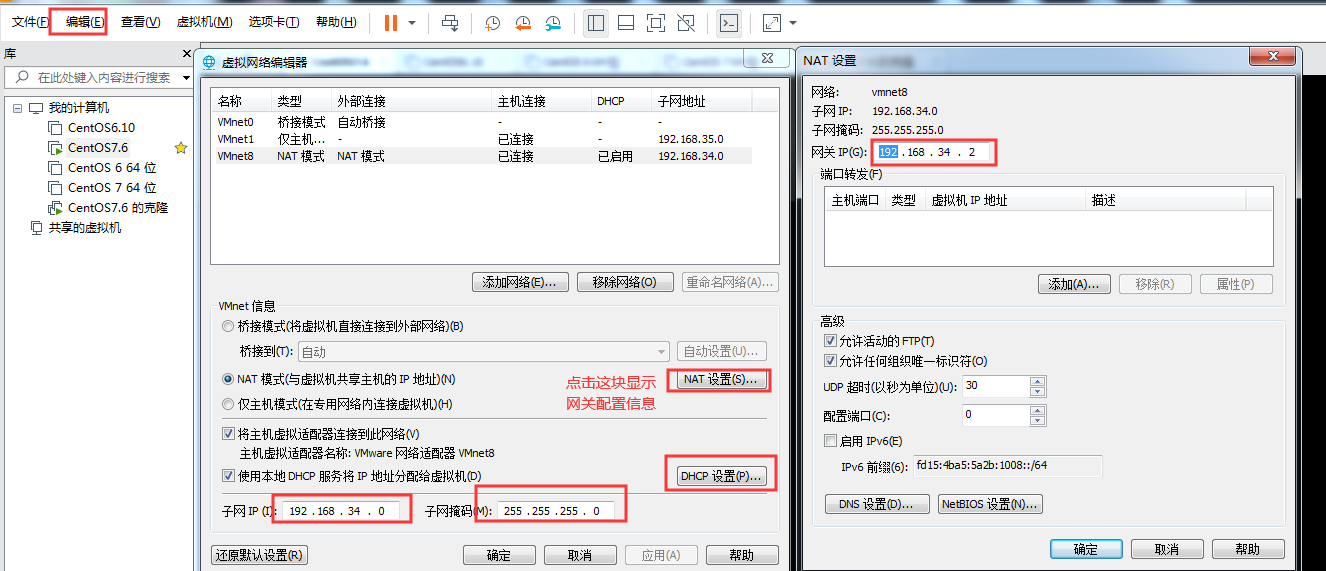
一、使用DHCP动态获取IP地址
在vmware虚拟机中点击编辑按钮,选择“虚拟网络编辑器”进行相关配置,选择VMnet8,然后再设置NAT设置里边的网关,此时的网关地址是192.168.34.2
网络ID是192.168.34.0,子网掩码是255.255.255.0
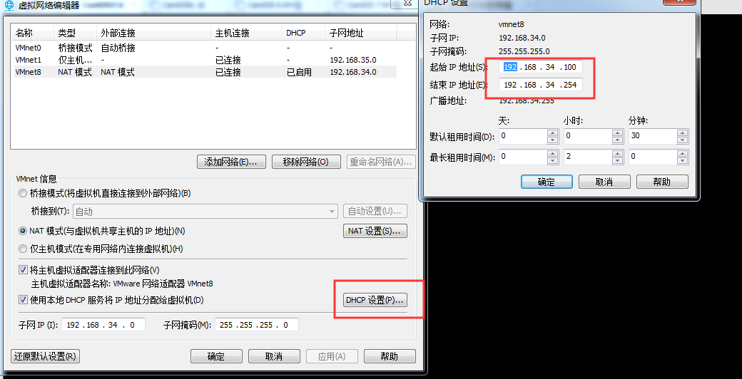
点开DHCP设置那里,可以设置IP地址段,此时的IP地址段是192.168.34.100-192.168.34.254之间的IP地址都可以获取:
修改IP地址的配置文件,将BOOTPROTO=dhcp即可,重启network服务就会自动获取IP地址
// 修改网卡eth0的配置文件则打开ifcfg-eth0文件
#vi /etc/sysconfig/network-scripts/ifcfg-eth0
DEVICE=eth0                     // 网卡设备名
BOOTPROTO=dhcp                  // 是否自动获取IP(none、static、dhcp),其中none和static都代表手工分配IP地址
HWADDR=00:0c:29:17:c4:09        // MAC地址
NM_CONTROLLED=yes               // 是否可以由Network Manager图形管理工具托管
ONBOOT=yes                      // 是否随网络服务启动,eth0生效,为no时ifconfig查看不到eth0网卡IP信息
TYPE=Ethernet                   // 类型为以太网
UUID="xxxxxx-xxxx..."           // 唯一识别码
IPADDR=192.168.0.252            // IP地址
NETMASK=255.255.255.0           // 子网掩码
GATWAY=192.168.0.1              // 网关
DNS1=202.106.0.20               // DNS
IPV6INIT=no                     // IPv6没有启用
USERCTL=no                      // 不允许非root用户控制此网卡
二、静态获取IP地址
修改相关的IP地址配置文件即可,修改完之后只需要重启network服务即可。
// 修改网卡eth0的配置文件则打开ifcfg-eth0文件
#vi /etc/sysconfig/network-scripts/ifcfg-eth0
DEVICE=eth0                     // 网卡设备名
BOOTPROTO=none                  // 是否自动获取IP(none、static、dhcp),其中none和static都代表手工分配IP地址
HWADDR=00:0c:29:17:c4:09        // MAC地址
NM_CONTROLLED=yes               // 是否可以由Network Manager图形管理工具托管
ONBOOT=yes                      // 是否随网络服务启动,eth0生效,为no时ifconfig查看不到eth0网卡IP信息
TYPE=Ethernet                   // 类型为以太网
UUID="xxxxxx-xxxx..."           // 唯一识别码
IPADDR=192.168.0.252            // IP地址
NETMASK=255.255.255.0           // 子网掩码
GATWAY=192.168.0.1              // 网关
DNS1=202.106.0.20               // DNS
IPV6INIT=no                     // IPv6没有启用
USERCTL=no                      // 不允许非root用户控制此网卡