Questions before a first answer: If the pin is configured as an output and write a high level, the connection LED will happen?
Result of the experiment, LED will light, but compared to the case where the output is high, the luminance is low. Why is this?
We know by the tutorial, the input and output pins are controlled by the mode register bits DDxn DDRx may be inferred pin_mode function will change the value of a pin corresponding DDxn, 0 is input, an output, and its reset is 0, i.e., input, and therefore if not the pin is configured as an output, which is the input pattern. Similarly pin_write function will change the PORTxn, the second parameter value is a function thereof.
It is not configured to output a result of the high level is written, this DDxn pin is 0, PORTxn 1, is a pull-up resistor input mode. Pull-up resistor corresponding to resistor VCC and then connected to the pin, a pin is connected to an external circuit is followed by a resistor to the LED, the LED may generally be equivalent to the one limiting resistor connected between VCC and ground , the LED will light.
The resistance of this resistor is the pull-up resistor and the original current limiting resistor and the resistance values, a relatively large pull-up resistor (according to datasheet P432 Figure30-164 can be estimated about 40 k pull-up resistor), compared to the flow restrictor resistance is the output resistance of the outer case of the high level, the LED on many small current, and therefore a correspondingly low brightness.
This is a problem in an analog circuit, digital circuit using only the analysis can not be solved. The short answer to this question also reflects a comprehensive knowledge of the microcontroller.
Today, in terms of digital control, is the development board two days left word.
Early glow lamp also become digital, rely on a gas discharge light emission point, now generally refers to the 7-segment (segment 7 as on the word), which is the essence of many LED. Our development board is two digital tube, there are one, three, four; and in addition there are 7-segment LED meter word, but relatively rare. Note 7-segment actually has eight segments, each number the lower right corner there is a decimal point. There is also a digital clock also four intermediate points, with two decimal points can not be turned.
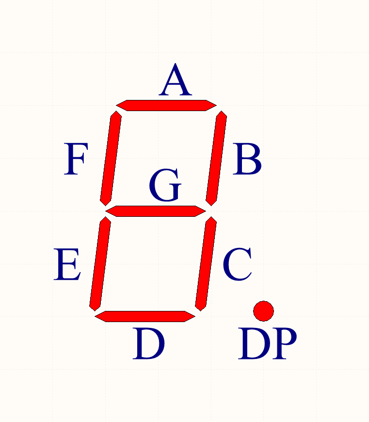
8-segment clockwise from the upper section of the order of A, B, C, D, E, F, the middle G, known as the decimal point DP.
The principles of various digital LED are the same, slightly different internal circuit connections. A digital has 10 pins, while the interior has eight LED, is how to connect it? Mentioned that a digital output through the common cathode and common anode, this is digital: 8 LED positive (or negative electrode) is connected to the two pins together, a negative electrode (or positive electrode) is connected to a lead feet, known as common anode (or common cathode) LED. 2 digital development board, each and every one common cathode connection.
The connection between the positive electrode 8 and the microcontroller is somewhat complex, it can not explain, but can be understood as controlled by the microcontroller 8, independent of output pins, each of the positive electrode is connected in series after the digital resistor. Two right and left pin is connected to the negative electrode of the digital right tube, the use of them should be connected to the microcontroller pins.
If you want a particular paragraphs bright LED should be how to configure the 9-pin level it? The answer is very high positive brighter segments, the other is low, the negative is low. Further, if the negative electrode is high, the LED between the positive and negative voltage is 0 or less, will not on, this fact is important when multi-bit digital driving. He notes that the negative low and high light does not shine, unlike previously used LED, written procedures do not take it for granted.
According to the manual, we can use segment_dec setting data digital display and other functions, with segment_display to make the digital display. The display setting data and control data into the display, respectively, to complete the two functions, to say what is the profound separation of data and view, and the reason closer to the theme of this tutorial, we'll see later, a number of digital alone can not be a multi-bit digital display function (at least in the order of control flow).
As the first digital control program, we first LED lighting right, it cycles through 0-9. Two right and left are connected to the negative electrode microcontroller pins 4 and 5.
 1 #include <ee1/segment.h>
 2 #include <ee1/delay.h>
 3
 4 int main()
 5 {
 6     segment_init(PIN_4, PIN_5);
 7     while (1)
 8         for (uint8_t i = 0; i != 10; ++i)
 9         {
10             segment_dec(i);
11             segment_display(SEGMENT_DIGIT_R);
12             delay(500);
13         }
14 }
According to the contents of the previous tutorial, you should not be difficult to deduce segment_display of digital negative to do the job right. Pin it to the level of a negative to show the connection down, pulled another, which is more evident. segment_display Digital cathode tubes do is disposed in the positive electrode 8 digital levels of the data, where the data is segment_dec set. Each data bit and a period of light and dark corresponds to the digital control, the lowest and the highest bit corresponds to the bit corresponding to the segment A segment DP (when this is only my connection board design and development). Then, the digital display needs a lighting section B and C, which display data is 0b00000110, i.e. 1 segment code number. segment_dec other functions based on the input parameter, an array of size 2 to write the two values, respectively corresponding to two digital data to be displayed.
Parenthetically, 0b prefix indicates a binary number, which is a GNU extension, not part of standard C, C ++ also began to support this notation from the C ++ 14. Compiler extensions should be used sparingly as possible Logically speaking, but this feature is really handy, so I used to use.
Some libraries have declared segment code. segment_digit of 0 ~ 9, A ~ F code segment, segment_dot decimal point, which is defined as:
 1 const uint8_t segment_digit[] =
 2 {
 3     0b00111111, // 0
 4     0b00000110, // 1
 5     0b01011011, // 2
 6     0b01001111, // 3
 7     0b01100110, // 4
 8     0b01101101, // 5
 9     0b01111101, // 6
10     0b00000111, // 7
11     0b01111111, // 8
12     0b01101111, // 9
13     0b01110111, // A
14     0b01111100, // B
15     0b00111001, // C
16     0b01011110, // D
17     0b01111001, // E
18     0b01110001  // F
19 };
20 const uint8_t segment_dot = 0b10000000;
These code segments are shaped according to a character input manually. You can create more characters in the same way, you can also find some tools on the Internet to complete.
If (if I mean) of the common cathode LED A ~ G, DP segments respectively connected to the microcontroller PA0 ~ PA7, then low negative electrode, are all 1. DDRA, the segment with a code assignment to the PORTA, can digital display corresponding numbers or letters, or other patterns. Questions remain here one, for a total of Yang digital tube, where should make some changes?
The above is a method of driving a digital control.
Now we look at how to drive more than digital. Development board is two digital tube, in fact, a number of digital driving method is the same, here in two common cathode LED, for example.
Mentioned a number of common cathode LED common cathode of each and every one connection, then the connection between different sites is how to do? Is there any connection between the two digital number two, the whole device has at least 18 pins, that number has some big. There is a circuit connection and can be done on a digital basis, based on each additional bit, only a multi-pin, as shown below:
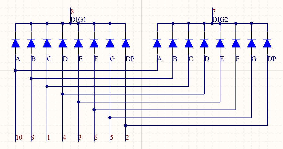
This increase is the new pin of an anode, cathode and that each paragraph and the first one is shared. For the same period of the different sites, they are not difficult to find common anode connection. Bits are common cathode and common anode segment is, in consideration of the habits, such as digital tube called the common cathode LED.
however. This saves pin connection comes at a price, in a moment that you can independently control 8 LED, 8 bit segment that is (according to symmetry, you can also control the same paragraph 2, but more so by limit). You can not do is bit 1 of the lighting segment A and segment B-2, while other segments are not bright. why? A 1 bit of the lighting sections, it is necessary to segment A high common anode and cathode common bit 1 is low, a high level segment B Similarly, the second bit is low, the result is the first one of a and B segments of the second paragraph is also lit simultaneously. Under this program, only two digital tube display the same number.
We need some other way. According to the contents of the previous section, respectively, in the two display any one can do it all. If you want to see two numbers, the program can display the number on the left in the first second, 2 seconds display digits to the right user at least is understandable, although this method is very bad. Why is 1 second instead of 10 seconds it? User case where the average wait 1 second 0.5 seconds can see the information of the two numbers, is 10 seconds, then wait five seconds, users do not want.
But now even 0.5 seconds users are not willing to wait, how do? We must take the wait time compression to zero it? The user is human, the human eye is not too high refresh rate, as long as there are 24 images per second, it (in fact, the brain) to think that these images are continuous. So long as this waiting time to obtain than the human eye image interval is smaller, the user will not complain.
Now you do the user. You can see two numbers, two numbers are presented in a very short interval of time, as short as you can not tell it in the end there is no paragraph spacing. what does this mean? Two figures show out. Behind this, the digital controller is switched every short period of time to a digital display, this driving method become dynamic scanning .
Let's write a program to test this approach. On the basis of a previous program, we make a left display 0.
 1 #include <ee1/segment.h>
 2 #include <ee1/delay.h>
 3
 4 int main()
 5 {
 6     segment_init(PIN_4, PIN_5);
 7     while (1)
 8     for (uint8_t i = 0; i != 10; ++i)
 9     {
10         segment_dec(i);
11         for (uint8_t j = 0; j != 250; ++j)
12         {
13             segment_display(SEGMENT_DIGIT_L);
14             delay(1);
15             segment_display(SEGMENT_DIGIT_R);
16             delay(1);
17         }
18     }
19 }
In this program, digital refresh interval is set to 2 ms (1 ms * 2). In effect, this interval of 10 milliseconds or less, the human eye do not feel the difference. In this program you can not even write latency (corresponding to the number of cycles to increase many times), the refresh interval is very small, but other applications in addition to the microcontroller LED driver there are other work, if the work is the running time not fixed, they can not be used to replace the delay, as it will result in uneven brightness LED. You should join a much longer time than the run of the delay interval to ensure roughly the same, but the program reaches 10 ms of this order of magnitude can not be used in other work running time.
When using a dynamic scanning to control the LED, you will find from one of unprecedented trouble, especially when combined with the input key or the like, the second as the job title. LED and other equipment previously used single call to a function, its status can be maintained until then call the appropriate function; dynamic scanning is dynamic, that is, you need to continue to control it, and this is the root of the trouble lies. Of course, there are other single-chip solutions to these problems, we revisit later.
Today's job:
1. holding a millisecond delay, the display switching time of from 0.5 seconds to 1 second (this is what is difficult, is not it?);
2. the following functions: when a key is pressed, the digital display hexadecimal number plus 1; holding press 1000 milliseconds, every 200 milliseconds number plus 1; then add another key, but its effect is digital minus 1.