Brief introduction
Vertex shader fragment, running on programmable hardware rendering pipeline, comprising the vertex program Vertex Programs and fragment programs Programs Fragment . When using the vertex program when program segments or rendered, graphics hardware fixed function pipeline will be closed, specifically, a vertex program written in the fixed line will replace the standard 3D transformation, lighting, texture coordinate generator functions, and fragment program will replace SetTexture texture blending mode command.
Vertex shader and fragment shading programs are usually exist, cooperate with each other, the output of which is input as the former . However, you can only vertex shader. If only vertex shading program, only the operation of the input vertices, the vertex point inside the automatic way in hardware default interpolation. For example, input a triangular facet, a vertex shader be phong lighting calculations, counting only the color of the light three vertices, and the color of the interior points of triangular facets default algorithm in hardware (fast or Gourand phong shading shading) interpolate, if more advanced graphics hardware, the default processing algorithms better (fast phong shading), then the effect will be good; if the graphics hardware using Gourand shading algorithms, Mach banding (striping) appears.
Since the GPU for processing data in parallel, each data shader program is executed once. I.e., vertex data of each vertex program is executed once; a fragment of each segment of the program will be executed.
Vertex And Fragment Shader
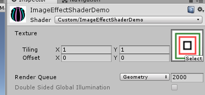
As before, we use an example of view, in the Project panel, right-click Create-> Shader-> Image Effect Shader, named ImageEffectShaderDemo.shader, as follows:
Shader "Custom/ImageEffectShaderDemo" {
	Properties {
		_MainTex ("Texture", 2D) = "white" {}
	}
	SubShader {
		// No culling or depth
		Cull Off ZWrite Off ZTest Always

		Pass {
			CGPROGRAM
			#pragma vertex vert
			#pragma fragment frag

			#include "UnityCG.cginc"

			struct appdata {
				float4 vertex : POSITION;
				float2 uv : TEXCOORD0;
			};

			struct v2f {
				float2 uv : TEXCOORD0;
				float4 vertex : SV_POSITION;
			};

			v2f vert (appdata v) {
				v2f o;
				o.vertex = UnityObjectToClipPos(v.vertex);
				o.uv = v.uv;
				return o;
			}

			sampler2D _MainTex;

			fixed4 frag (v2f i) : SV_Target {
				fixed4 col = tex2D(_MainTex, i.uv);
				// just invert the colors
				col = 1 - col;
				return col;
			}
			ENDCG
		}
	}
}
Some front surface shader and the same content that we will not go into details. About Cull Off ZWrite Off ZTest Always the same piece of content we will separately explain: https://blog.csdn.net/wangjiangrong/article/details/89335208
#pragma
| #pragma vertex vert | The function name of the program code into a vertex |
| #pragma fragment frag | The function name of the compiled program code into segments |
#include
Shader time of writing, we can use as a header file in C ++, the use of #include preprocessor directive to include other code sets. This tells Unity we want the current Shader using code contained in these files. We do this in fact is the inclusion of Cg code snippet in the appropriate location.
#include "UnityCG.cginc" reference UnityCg.cginc headers (Unity installation directory> Editor> Data> CGIncludes lower) can use predefined structure directly, they respectively appdata_base, appdata_tan and appdata_full:
struct appdata_base {
    float4 vertex : POSITION;
    float3 normal : NORMAL;
    float4 texcoord : TEXCOORD0;
};

struct appdata_tan {
    float4 vertex : POSITION;
    float4 tangent : TANGENT;
    float3 normal : NORMAL;
    float4 texcoord : TEXCOORD0;
};

struct appdata_full {
    float4 vertex : POSITION;
    float4 tangent : TANGENT;
    float3 normal : NORMAL;
    float4 texcoord : TEXCOORD0;
    float4 texcoord1 : TEXCOORD1;
    fixed4 color : COLOR;
};
Vertex program input:
#pragma vertex vert vert function specified vertex program, which has one input parameter may be predefined CS three above-mentioned input parameters appdata_base, appdata_tan and appdata_full, we can also customize, e.g. in the example appdata. Note that since the structure defined attributes can only choose from the following properties (particularly type may not be the same, such fixed4 color)
| float4 vertex:POSITION | Vertex position |
| float3 normal:NORMAL | Vertex normals |
| float4 texcoord:TEXCOORD0 | The first UV coordinate |
| float4 texcoord1:TEXCOORD1 | The second UV coordinate |
| float4 color:COLOR | Each vertex (per-vertex) Color |
| float4 tangent:TANGENT | Tangent vector (used in the normal map) |
Knowledge Point 1: vertex coordinates and the tangent line is float4 ,: where it represents a homogeneous coordinates, such us represents a float4 (x, y, z, w), when w = 1 it indicates the point (x, y, z), when w = 0 when it represents a vector (x, y, z). Difference here, means that when W is 1 dot, the vector is represented as W 0 .
Knowledge Point 2: sub-normal vector binoraml, it can be obtained and computed from the noraml tangent, formula is as follows:
float3 binormal = cross( v.normal, v.tangent.xyz ) * v.tangent.w;Knowledge Point 3: TEXCOORD0 and texcoord1 represent two UV, sometimes we need multiple textures on the model posted a picture together, then there will be affixed to two layers UV.
Input program fragment:
Previously mentioned, the output of the program is the input segment vertex program. Output vertex program must contain variable POSITION semantics, the value can not be used directly in the program segment, it is only used for rasterization. Custom semantic data can be used to represent words TEXCOORD series.
Vertex program:
GPU vertex shader program extracts from the front end module (register) information primitive (vertex positions, normals, texture coordinates, etc.), and the vertex coordinate space to complete the conversion, the conversion method vector space, lighting calculations and other operations, and finally the calculated data to a specified register for a fragment program.
v2f vert (appdata v) {
	v2f o;
	o.vertex = UnityObjectToClipPos(v.vertex);
	o.uv = v.uv;
	return o;
}
V2f example is the output of the vertex program, the program segment is also input, as AppData vertex program input. Vertex position input vertex program assigned to the post-processing v2f, while uv assigned to the input value of v2f.
Built-in functions:
| many (M, V) | M is a matrix and the vector V for dot to obtain a vector Z, Z is the vector of the vector V obtained value matrixed |
| float4 UnityObjectToClipPos(float3 pos) | It is equivalent to: mul (UNITY_MATRIX_MVP, float4 (pos, 1.0)), but more efficient. The apex transition from model space to clip space |
| float3 UnityObjectToViewPos (float3 post) | It is equivalent to: mul (UNITY_MATRIX_MV, float4 (pos, 1.0)), but more efficient |
| float3 WorldSpaceViewDir (float4 v) | Parameter is the vertex coordinates of the model space, made under the direction of pointing the camera in world space, that is, viewing direction |
| float3 ObjSpaceViewDir (float4 v) | Above, but get to the viewing direction is in the model space |
| ... ... | |
Built-in matrix (float4x4):
| UNITY_MATRIX_MVP | The current modelview projection matrix for the vertex / direction vector transformation from model space to clip space |
| UNITY_MATRIX_MV | The current model view matrix, vertex / direction vectors for transforming from model space to viewing space |
| UNITY_MATRIX_V | Current observation matrix for the vertex / direction vector transformed from world space to viewing space |
| UNITY_MATRIX_P | The current projection matrix, vertex / direction vectors for transforming from observation space to clip space |
| UNITY_MATRIX_VP | Current observation projection matrix for the vertex / direction vector transformed from world space to the clip space |
| UNITY_MATRIX_T_MV | The model view matrix transpose |
| UNITY_MATRIX_IT_MV | Unpivot model view matrix for conversion from the normal model space to viewing space, can also be used to obtain the inverse matrix of UNITY_MATRIX_MV |
| _Object2World | The current model matrix, vertex / direction vectors for transforming from model space to world space |
| _World2Object | Inverse current world matrix, vertex / direction vectors for transforming from model space to world space |
space:
| Model space (model space / object space) | Each model has its own model space, when it is rotated or moved, the model space will also move. |
| World space (world space) | 宏观的特殊坐标系,在Unity中模型如果没有父节点,那么它就在世界空间内 |
| 观察空间(view space / camera space) | 以摄像机为原点 |
| 裁剪空间(clip space) | 其矩阵为投影矩阵,裁剪图元,并为投影做准备 |
| 屏幕空间 | 屏幕左下角是(0, 0),右上角是(pixelWidth, pixelHeight) |
顶点着色器的最基本任务就是把顶点坐标从模型空间转换到裁剪空间中,模型空间 -> 世界空间 -> 观察空间 -> 裁剪空间 -> 屏幕空间。
片段程序:
片段着色程序从顶点程序存放数据的寄存器中获取需要的数据,通常为“纹理坐标、光照信息等”,并根据这些信息以及从应用程序传递的纹理信息(如果有的话)进行每个片段的颜色计算,最后将处理后的数据送光栅操作模块。
片段就是所有三维顶点在光栅化之后的数据集合,这些数据没有经过深度值比较,而屏幕显示的像素是经过深度比较的。
片段着色程序是对每个片段进行独立的颜色计算,并且算法由自己编写,不但可控性好,而且可以达到更好的效果。片段程序通常只输出一个COLOR(最终颜色)。
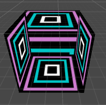
fixed4 frag (v2f i) : SV_Target {
	fixed4 col = tex2D(_MainTex, i.uv);
	// just invert the colors
	col = 1 - col;
	return col;
}
这段代码的含义即将贴图中每个顶点的新颜色 = 1 - 原颜色。即黑的变白的,白的变黑的。得到的效果如下: