STP和RSTP配置
Experiment 1: STP configuration
operational requirements
-
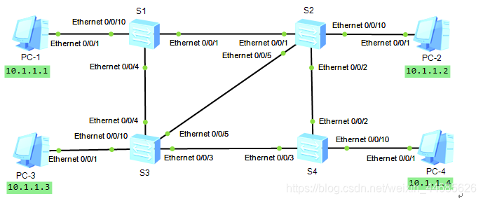
Use the following structures topology eNSP
-
Configuration 4 IP address of the PC, and the detection of each of the direct communication link;
-
Then the spanning tree state in S1, S2, S3 and S4
Display Brief STP -
Close in the S1, S2, S3 and S4 STP (Huawei devices enabled by default MSTP), an analog broadcast storm;
Sl / S2 / S3 / S4: Use the undo enable STP
PC2: -t of ping 10.0.0.3 -
Enable STP (Huawei devices enabled by default MSTP), the switch mode to STP mode on S1, S2, S3, and S4;
[SW4 is] STP enable
[SW4 is] MODE STP STP -
The spanning tree state S1, S2, S3 and S4 of;
-
S4 is the root bridge
2) SW1-SW3 SW2-SW3 link between the backup link
indicating achieved STP loop avoidance function3) simulated primary link fails, STP link backup verification
PC2: ping 10.0.0.3 -t
the interface shutdown of the main chain
SW3 display stp // observe the interface before blocking occurs when the main link failure The change
-
The priority to 0 S1, S2 priority to 4096, the spanning tree states S1 and S2;
SWl: Stp SW2 priority 0: STP priority 4096
Note: Priority value must be a multiple of 4096 or 0 -
Remove just configured priority, and then configured as a master root switch S1, S2 is the root switch, see S1 and S2 of the spanning tree;
SWl / SW2: Use the undo STP priority
SWl: Primary SW2 STP the root: the root STP Secondary -
Configuration changes are S4 root port cost is the cost 2,000,000, observing the costs of ports and port status STP;
- By the S4 see which port display stp is RP
- Into the root port, use the stp cost 2000 000 stp cost of modifying the value of the port
10 Configuring STP timers.
a) continuously sends ICMP packets to test connectivity using PC-2 ping -t. 4-command on the PC;
B) on the Forward Delay modified S1 is 2000CS, default 1500cs, cs representative of hundredths of a second. Note: This configuration takes effect only performed on the root switch;
C) Check that the timer value S1, the PC-2 was observed connectivity test results. 4-on the PC;
D) using the command set stp bridge-diameter network diameter, the diameter of the network switches automatically calculate the optimum values of the three time parameters;
E) Check that the timer value S1, the PC-2 was observed connectivity test results. 4-on the PC;
12. the verification Forward Delay timer.
a) See port status 4 switch;
B) to S4 root port is closed, so that the backup port becomes the new root port, observed PC-2 connectivity test results on the PC-4;
C) the original to S4, recovery root port, and a network change on S1 diameter default 7, view the information on the STP S1, PC-2 was observed connectivity test results on PC-4;