Transient interference voltage and current is the main cause of damage to the electronic circuits and devices, often incalculable damage to people. Start-stop operation of these disturbances usually comes from power equipment, unstable AC power grid, lightning interference and electrostatic discharge, transient disturbances almost everywhere and at all times there, people feel very hard to detect. Fortunately, an efficient energy occurs TVS circuit protection device so that transient disturbances are effectively suppressed.
TVS (TRANSIENT VOLTAGE SUPPRESSOR) or said transient voltage suppression diode is a new product developed on the basis of the process regulator, the same symbols and the circuit common zener diode, the shape is no different from ordinary diode, when the TVS when subjected to transient high energy impact at both ends, it can very high speed (up to 1 * 10-12 seconds) so that impedance suddenly decreases, while absorbing a large current, clamping the voltage between the both ends thereof in a the predetermined value, thereby ensuring that the back of the circuit elements from transient high energy impact damage.
TVS characteristics and parameters
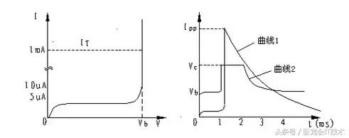
FIG 1 TVS characteristic
1.TVS features
If the viewing characteristics of the TVS with tracers, can be obtained the waveform shown in FIG. 1 the left. If the single view on this curve, TVS tube breakdown characteristics common regulator and there is no difference, a typical PN junction avalanche device.
http://www.eda365.com/forum-271-1.html
But this curve reflects only a part of the TVS characteristics must also complement the characteristic curve shown on the right in order to reflect all the features of TVS. This is when the current and voltage waveforms observed in dual trace oscilloscope TVS withstand a large current surge.
FIG 1 is a graph of a current waveform of TVS, TVS which represents the current flowing through the tube suddenly rises from 1mA to a peak, and then decreased exponentially, the cause of such a current surge may be lightning overvoltage. Curve 2 is a waveform of the voltage across the TVS, TVS which represents the current suddenly rises, the voltage across the TVS will also rise, but only rises to a maximum VC value which is slightly larger than the breakdown voltage VBR, thereby circuit elements behind the protection.
TVS parameters

FIG 2 TVS and Parameters
A. breakdown voltage (VBR): TVS impedance suddenly decreases at this time, in the avalanche breakdown state.
B. test current (IT): TVS obtained by measuring the breakdown voltage VBR at this current. 1MA take under normal circumstances.
C. Reverse displacement voltage (VRWM): TVS maximum rated DC working voltage, when the voltage across the TVS continues to rise, the TVS in a high impedance state.
D. The maximum reverse leakage current (IR): measured at the operating voltage of the maximum current flowing through the TVS.
E. maximum peak pulse current (IPP): TVS allowed maximum surge current flows, which reflects the TVS surge suppression capability.
F. maximum clamping voltage (VC): TVS tube when subjected to high transient energy impact, large current flows through the tube, the IPP is the peak value, the terminal voltage value to the VC increased from VRWM value no longer increased, thereby achieving protection effect. After the surge, the IPP decay exponentially with time, when the attenuation to a certain value, begins to drop the voltage across the TVS VC, to restore the original state. Than the maximum clamp voltage VC and the breakdown voltage VBR said clamping factor Cf, expressed as Cf = VC / VBR, generally clamped factor of only 1.2 to 1.4.
G. peak pulse power (PP): PP Press peak pulse power into four different TVS with 500W, 600W, 1500W and 5000W. Maximum peak pulse power: Maximum peak pulse power: PN = VC · IPP. Obviously, the greater the maximum peak pulse power, TVS can withstand greater peak pulse current IPP; on the other hand, after determining the peak pulse power rating PP, TVS can withstand the peak pulse current IPP, as the maximum clamping voltage VC the decreases. TVS power addition and maximum allowable pulse peak pulse current and clamping voltage related, and also the pulse waveform, pulse duration, and ambient temperature.
TVS can withstand momentary pulse peak of up to several hundred amperes, which clamping response time of 1 * 10-12 seconds; TVS allowable forward surge current, at 1/120 sec 25 ℃, also up to 50-200 amps. In general, TVS can withstand momentary pulse pulses is not repeated. The actual applications, the circuit in repetitive pulse may occur.
TVS device is specified, the pulse repetition rate ratio (ratio of pulse duration and the interval of time) was 0.01%. If you do not meet this condition, accumulated pulse power has the potential to TVS burned. Circuit designers should be aware of this. TVS job is secure, even if the long-term impact to withstand high energy pulse is not repetitive large, "aging" problem does not appear. Test proved, TVS security after 10,000 pulses, the maximum allowable pulse power is still more than 80% of the original value.
TVS circuit element is mainly used for fast overvoltage protection. It can "absorb" up to several kilowatts of power surge signal. TVS has a small size, high power, fast response, noise, and low price advantages, it is widely used, such as: household appliances; electronic equipment; Instrumentation; sophisticated equipment; computer system; communication equipment; RS232, 485 and CAN other communication port; protection of ISDN; I / O ports; the IC circuit protection; audio and video input; AC and DC power; motor fields, noise suppression relay and the like. Overvoltage it can effectively lightning human error, caused by an impact load switch protective effect, the following are some typical examples TVS circuit applications.
TVS selection method
1. The protection circuit is determined to be a DC voltage or continuous operating voltage. If alternating current, calculate the maximum value, effective value * 1.414.
2.TVS reverse displacement voltage i.e. operation voltage (VRWM) - selection of TVS VRWM greater than or equal to the operation voltage defined in above step 1. This ensures that under normal operating conditions current TVS absorption is negligible, if the voltage is higher than a predetermined step of VRWM TVS, TVS will absorb a large amount of leakage current in the avalanche breakdown state, thus affecting the operation of the circuit.

3. The maximum peak pulse power: determining an interference pulse in the circuit, the waveform, the pulse duration of the pulse interference, determining the interference can be effectively suppressed TVS peak pulse power.
4. TVS selected maximum clamping voltage (VC) should be lower than the maximum withstand voltage is allowed by the protection circuit.
5. unipolar or bipolar - often there such a misconception that is used to inhibit reverse bidirectional TVS surge pulse, in fact, not the case. Bidirectional TVS or alternating current from a case of positive and negative bidirectional pulses. TVS is sometimes used to reduce capacitance. If the circuit only positive signal level, then the unidirectional TVS is sufficient. TVS operates as follows: When a positive surge, TVS avalanche breakdown in the reverse state; reverse surge, similar TVS diode forward biased and conducting the same to absorb the surge energy. In the case of low capacitance in the circuit is not the case. Should be used to protect the damage bidirectional TVS circuit of a low capacitive device against reverse surge.
6. If you know the more accurate inrush current IPP, you can use VC to determine its power, if you can not determine the approximate range of power, in general, choose power bigger is better.