
1. Applicable environment
1. The enterprise has its own physical professional server, and when some sensitive data is not leaked out, openmediavault is used to build a self-built NAS system;
2. A self-built NAS system is built in a virtualized environment for intranet work, or when traveling to work on an external network. file sharing;
3. There are available disk resources in the virtualization environment, which are used to dynamically expand the capacity of the NAS system;
4. On the basis of RAID 5, the original data resources can be expanded without loss, and a damaged physical hard disk can be directly replaced to recover the data;
5. By avoiding the direct opening of port 445, the ransomware virus is prevented from attacking the intranet server.
2. Initial environment
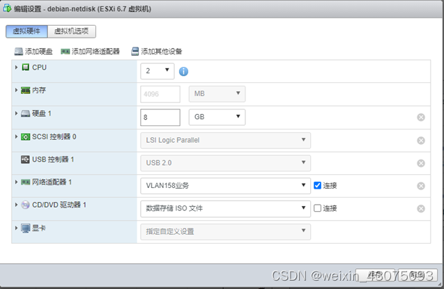
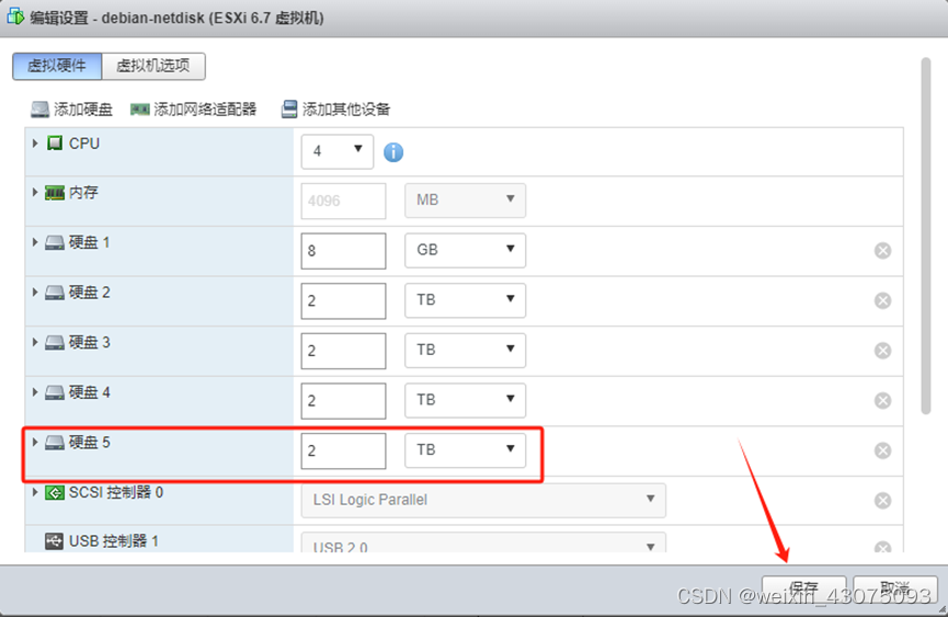
1. The virtual hardware situation of vm server in vmware esxi 6.7 environment, as shown below:
2. The openmediavault used as Nas storage system is Debian linux
link: https://pan.baidu.com/s/11YohlAirDOHuzYqb6MBccQ
extraction code: 1ne7
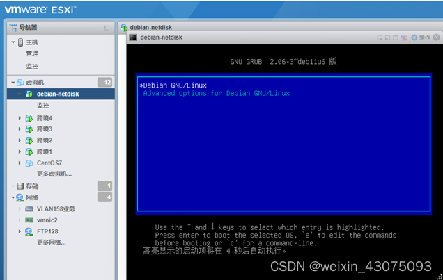
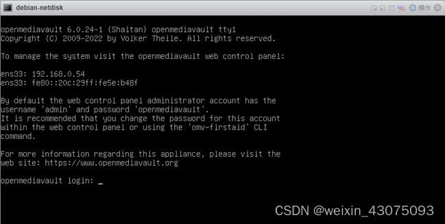
3. The interface after starting the openmediavault system is as shown below:
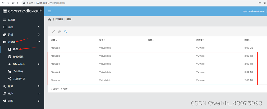
4. Currently there is only one disk, which is used to store the openmediavault startup system, as shown below:

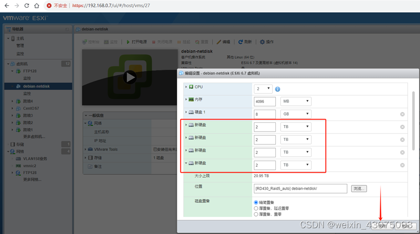
5. After shutting down the vm server, add four 2TB virtual hard disks to store the initial deployment data, as shown below:
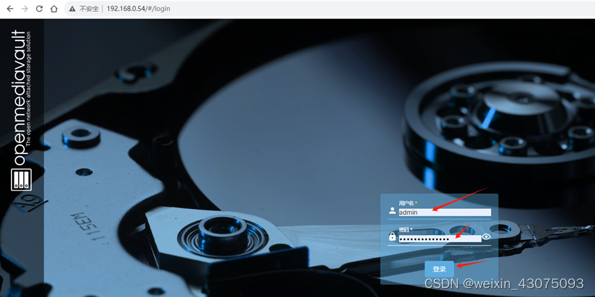
6. Open the server-side management address http://192.168.0.54 from the browser.
The initial user name and password are admin.
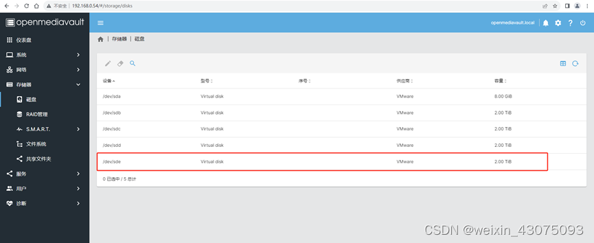
After logging in to openmediavault, you can see the disk item in the storage, and the four newly added 2TB disks appear in the list, as follows picture:
7. Create a raid5 volume, as shown below:
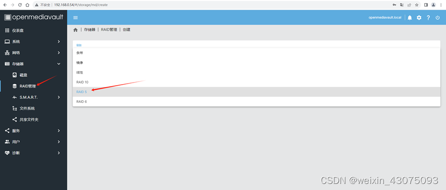
Raid volume:
(1) Stripe: RAID 0, which has high performance and is insecure. The capacity is the sum. It is the simplest form of setting up a disk array and only requires more than 2 hard disks. RAID 0 is the best-performing combination of hard drives in a RAID disk array, but does not provide redundancy or error recovery capabilities. According to certain rules, files are split and stored in RAID 0. Once one hard disk is damaged, all data in the entire RAID 0 will be lost.
(2) Mirroring: RAID 1 (mirror) has poor security and high performance, and its capacity is halved. Consists of at least 2 hard drives. The principle is to mirror the data of one disk to another disk. That is to say, when the data is written to one disk, a mirror file will be generated on another idle disk. As long as at least one disk in any pair of mirror disks in the system can be used, the system can run normally even if half of the number of hard disks fails. It has the worst performance and the best data security among RAID disk arrays, and will lose half of the hard drive capacity.
(3) Linear: JBOD (linear) JBOD is not a standard RAID level. It has only been proposed by some manufacturers in recent years and has been widely adopted. Although JBOD makes multiple disks appear to be just one, it does this by merging multiple drives into one large logical disk. JBOD's use of independent disks does not bring any benefits. In theory: if any hard disk is damaged, the entire JBOD will be unusable. Data on an undamaged hard drive will not be lost, but there is a threshold for recovering the data.
(4) Raid10: combines the characteristics of raid0 and raid1. It requires at least 4 hard disks, each 2 hard disks form a RAID 1, and 2 RAID 1s form a RAID 0. Performance and security are balanced in RAID 0 and RAID 1. Performance: worse than RAID 0, better than RAID 1. Security: Same as RAID 1. Half of the hard drive capacity will be lost.
(5) Raid5 RAID 5 is called "distributed parity independent disk structure" and requires at least 3 hard disks.
Each time a file is stored in RAID 5, of the 3 hard disks: 1 is used to store the file; 2 are used to generate parity information. As long as only 1 hard drive in RAID 5 is damaged, the hard drive can be replaced and the data restored. 1 hard drive capacity will be lost.
(6) Raid6 is an extension of RAID 5 and requires at least 4 hard drives. Each time a file is stored in RAID 6, of the 4 hard disks: 2 are used to store the file; 2 are used to generate parity information. As long as any two hard drives in RAID 6 are damaged, you can replace the two hard drives and recover the data. 2 hard drive capacity will be lost.
8. Check three 2TB disks and save, as shown below:
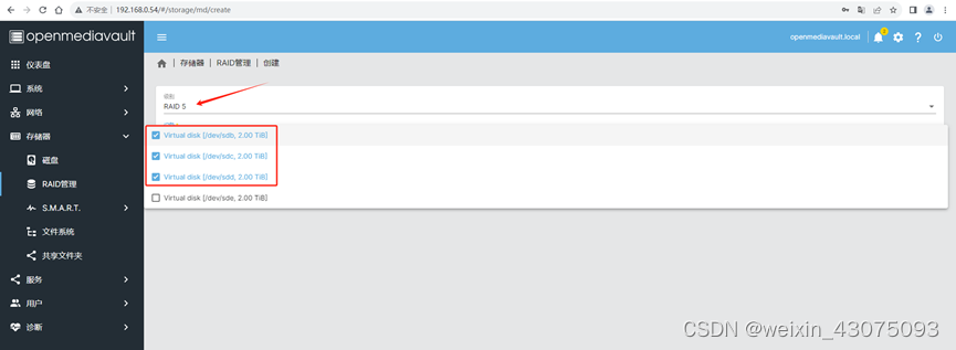
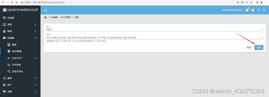
9. According to the characteristics of RAID5, three 2TB disks are combined to generate a 4TB volume. Click the check mark in the upper right corner to make the application effective.
(1) Create a RAID5 array, as shown below:
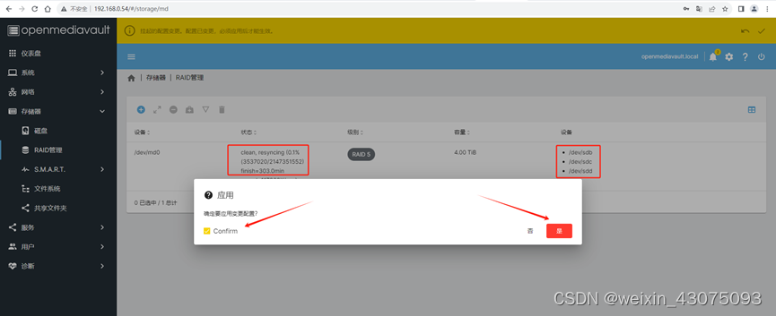
As can be seen from the prompt in the red box, it takes 303 minutes to complete this process. Wait for the array creation to be completed
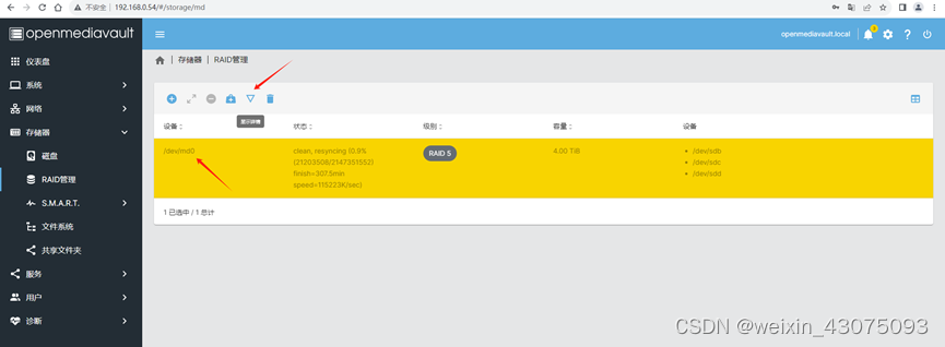
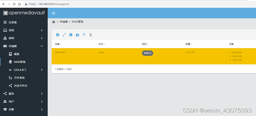
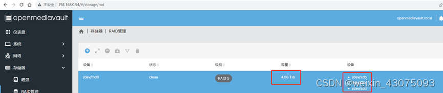
(2) Check the current RAID5 status, as shown below:
(3) It can be seen that the current status is clean and normal, resyncing is in progress, and 61% is completed (it has taken about 3 hours), as shown below:
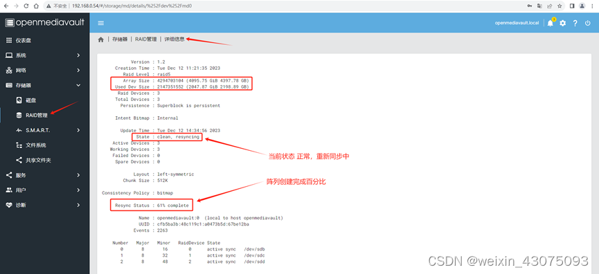
(4) 4 states of the raid array:
Resyncing: resynchronization, the state of synchronization when creating the array
Clean: the normal state of the array
Reshaping: reshaping the array, the state of data recovery
Degraded: degradation, the state of deleting a disk in the array Status
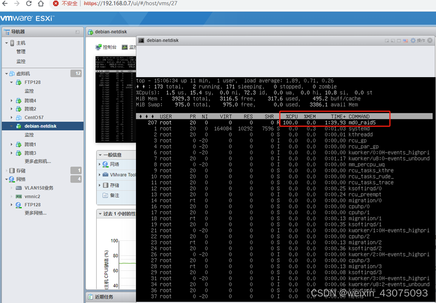
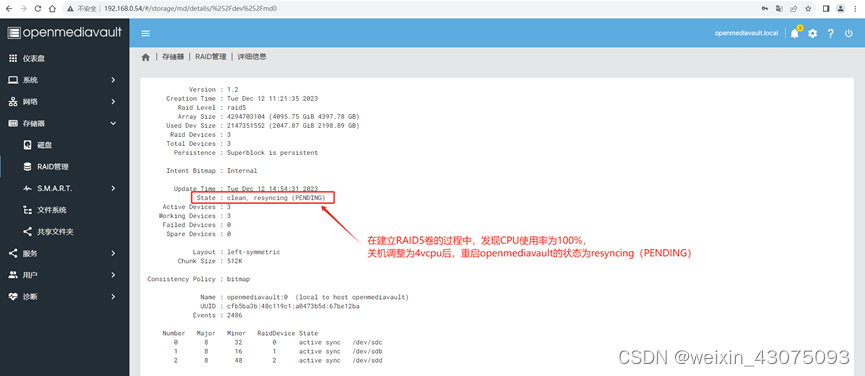
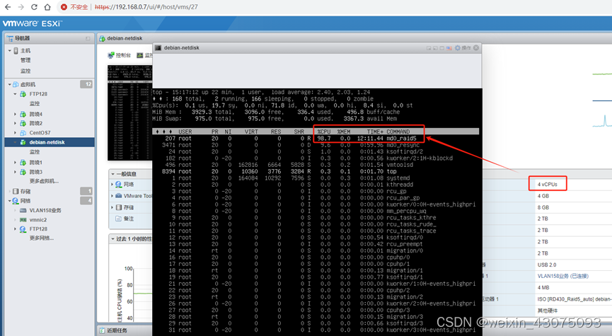
10. It takes a long time to establish RAID5. When using the top command to check the hardware working status, the CPU usage is 100%.
(1) Use the top command to check the running status of each process, as shown below:
(2) So I shut down and adjusted the number of vCPUs from 2vcpu to 4vcpu. Then after starting openmediavault, I saw that the status of RAID5 was clean, resyncing (PENDING) -> normal, resynchronized (to be determined), as shown below:
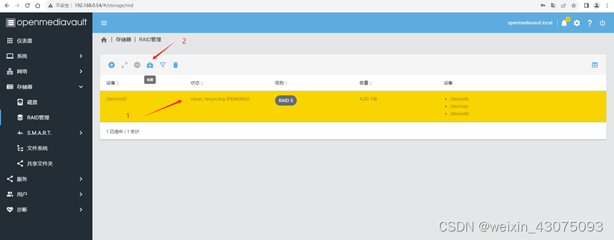
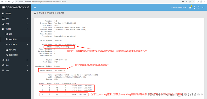
11. After selecting the RAID5 array, perform single-point recovery. Select the 2TB that has not been added to the array. After saving, resume the process of creating RAID5 and restore it from the pending state to the resyncing state, as shown below:
(1) The pending state, as shown below :
(2) It can be seen that /dev/sde has been added to the device and restored to the state of resyncing and reconstruction, as shown below:
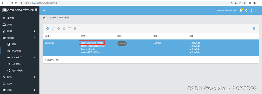
From the system's perspective, it is equivalent to adding a new disk to the RAID 5 array that has not yet been created.
(3) Look at the detailed information of the RAID5 volume, as shown below:
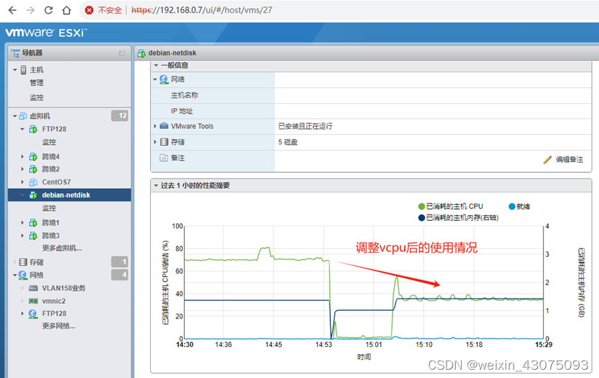
(4) After adjusting 2 vcpu to 4 vcpu, look at the status of the CPU and process as shown below:
(5) Check the CPU usage of this virtual machine from the vmware ESXI platform, as shown below:
(6) After creating the RAID5 array, (one 2TB is used for expansion, the capacity is not included) as shown below:
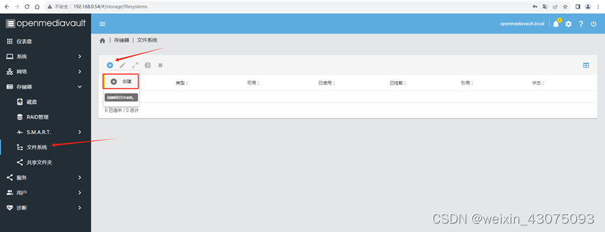
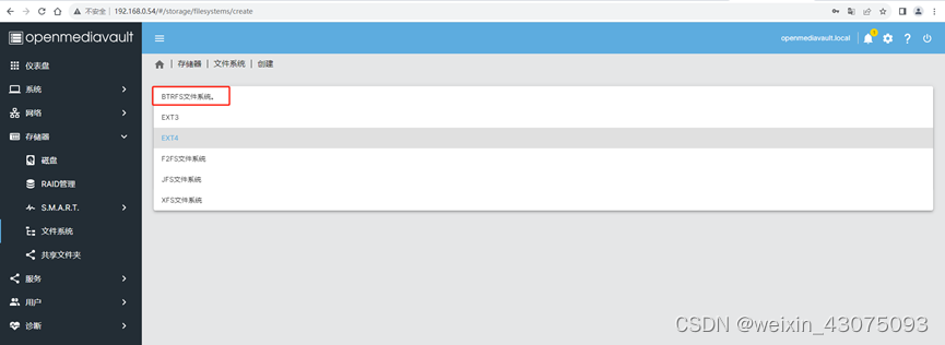
12. Create file system
(1)ext2
ext2是Linux操作系统最早的文件系统之一,它采用了基于磁盘组织的方式对文件进行存储,支持文件和目录的权限控制,但不支持日志功能。由于没有日志功能,如果系统崩溃或掉电,可能会导致文件系统损坏。
(2)ext3
ext3是在ext2的基础上添加了日志功能的文件系统,它可以记录文件系统的操作和状态,使得在系统崩溃或掉电时可以更快速地恢复文件系统的一致性。ext3支持较大的文件和分区,但在大文件和高并发读写的情况下,性能可能会受到一定的影响。
(3)ext4
ext4是在ext3的基础上进行改进的文件系统,它支持更大的文件和分区,提高了文件系统的性能和可靠性。ext4还支持更快速的文件系统检查和修复,同时也支持更高级的数据完整性保护机制。
(4)XFS
XFS是一种高性能、可伸缩的日志文件系统,它支持大文件和高并发读写,适用于大型服务器和高性能计算环境。XFS的日志机制更为健壮,代码结构也更为简洁,因此在高负载、高并发的情况下性能表现更为出色。
(5)Btrfs
Btrfs是一种新型的文件系统,它支持快照、压缩、数据镜像和数据校验等高级特性,适用于数据存储和备份。Btrfs还支持动态扩展和收缩文件系统大小,可以动态添加或删除磁盘,使得系统更为灵活和可靠。
总体来说,不同的文件系统适合不同的场景,需要根据实际需求进行选择。如果需要高性能、高并发的读写操作,可以考虑选择XFS;如果需要高可靠性、高数据完整性保护的文件系统,可以考虑选择ext4;如果需要数据存储和备份,可以考虑选择Btrfs。
(6)F2FS
F2FS (Flash Friendly File System) 是专门为基于 NAND 的存储设备设计的新型开源 flash 文件系统。特别针对NAND 闪存存储介质做了友好设计。F2FS 于2012年12月进入Linux 3.8 内核。F2FS仅支持Linux操作系统。
(7)JFS
( JOURNAL FILE SYSTEM),一种字节级日志文件系统,借鉴了数据库保护系统的技术,以日志的形式记录文件的变化。JFS通过记录文件结构而不是数据本身的变化来保证数据的完整性。这种方式可以确保在任何时刻都能维护数据的可访问性。该文件系统主要是为满足服务器(从单处理器系统到高级多处理器和群集系统)的高吞吐量和可靠性需求而设计、开发的。JFS文件系统是为面向事务的高性能系统而开发的。在IBM的AIX系统上,JFS已经过较长时间的测试,结果表明它是可靠、快速和容易使用的。 JFS也是一个有大量用户安装使用的企业级文件系统,具有可伸缩性和健壮性。与非日志文件系统相比,它的突出优点是快速重启能力,JFS能够在几秒或几分钟内就把文件系统恢复到一致状态。
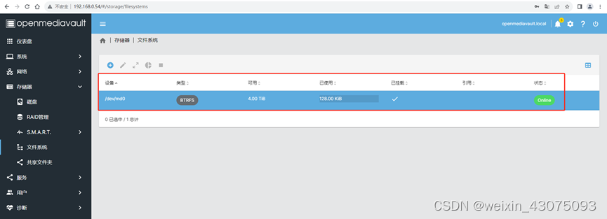
13、这里我们选BTRFS文件系统(根据具体环境的需求选择),如下图:
14、保存后,应用更改,生成一个4TB的BTRFS文件系统
(1)选择文件系统与磁盘,如下图:
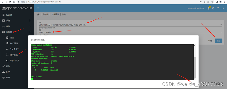
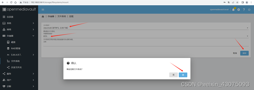
(2)创建文件系统完成,选择挂载告警阈值,默认85%,如下图:
15、右上角的勾,使应用生效
(1)选中confirm,是,如下图:
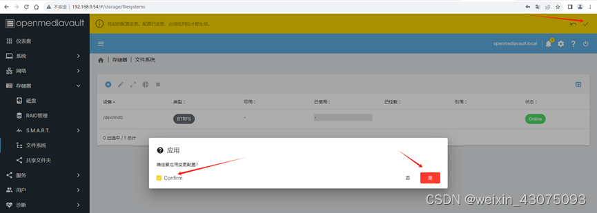
(2)应用生效后,如下图所示:
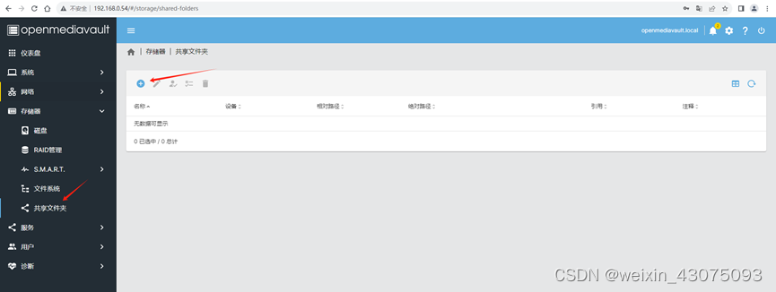
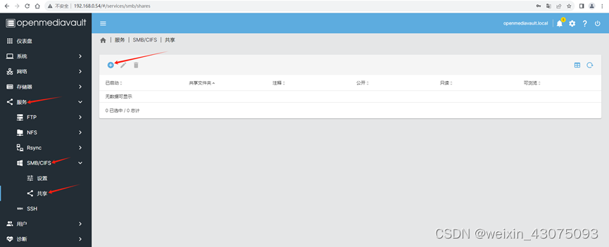
16、新建一个共享
(1)左侧选“共享文件夹”,再点+号,如下图:
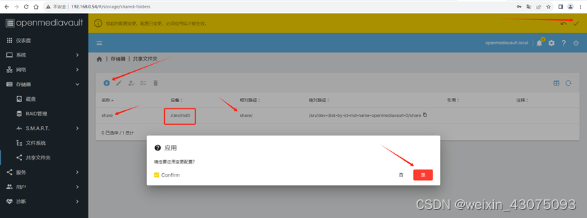
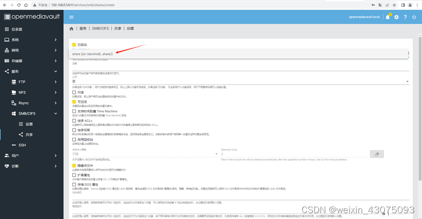
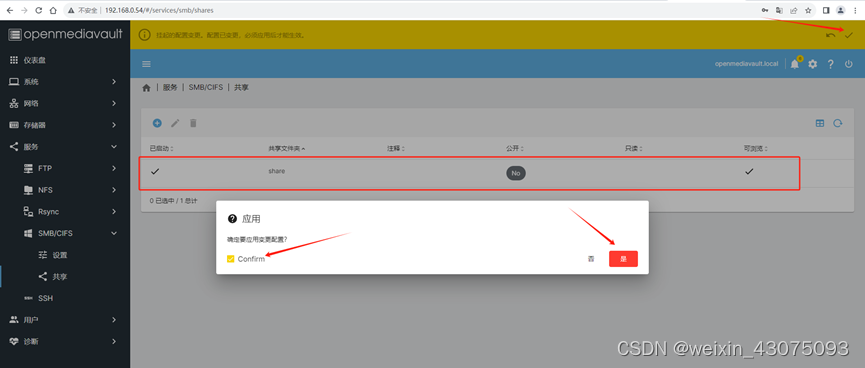
(2)指定共享名称、文件系统、共享路径、配置权限,保存,生成新共享share,右上角勾,confirm,是,使设置生效,如下图:
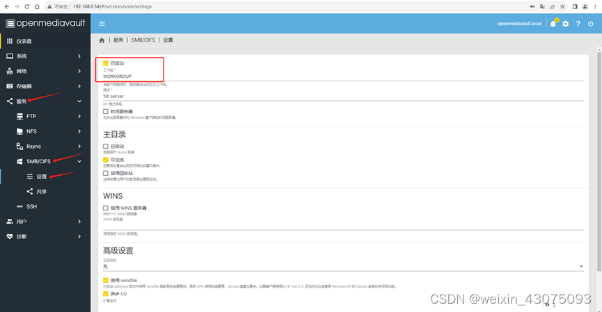
17、配置共享服务
(1)服务、SMB/CIFS、设置,勾选已启动,滚动条拖到右下方,保存,如下图:
(2)右上角勾,confirm,是,使设置生效,如下图:

(3)服务、SMB/CIFS、共享,+号创建,如下图:
(4)选择共享所在挂载,如下图:
(5)右上角勾,confirm,是,如下图:
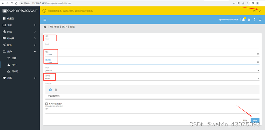
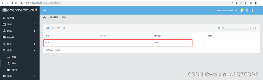
18、新建用户,用于登录共享的服务器文件夹
(1)用户,用户,+号,如下图:

(2)指定用户名user,密码123456,用户所在组users,保存,如下图:
(3)可以从列表中看到新建好的用户,如下图:
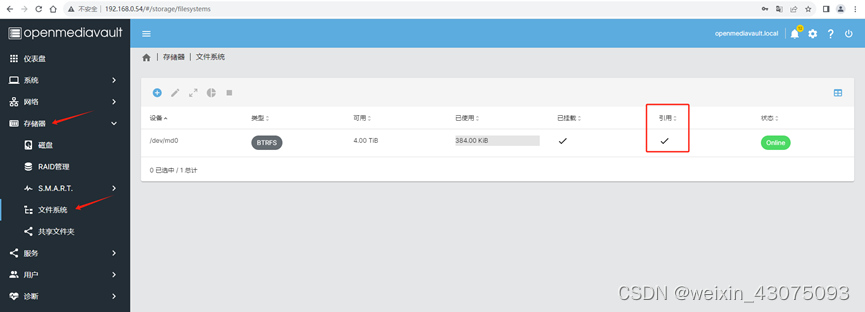
(4)回到存储器、文件系统,可以看到已经挂载和引用的磁盘(最初创建好文件系统时,只有挂载,无引用的勾,现在挂载和引用都打勾了,且是online在线状态),如下图:
三、内网访问测试:
1、打开一个文件夹,在地址栏输入,\192.168.0.54如下图:
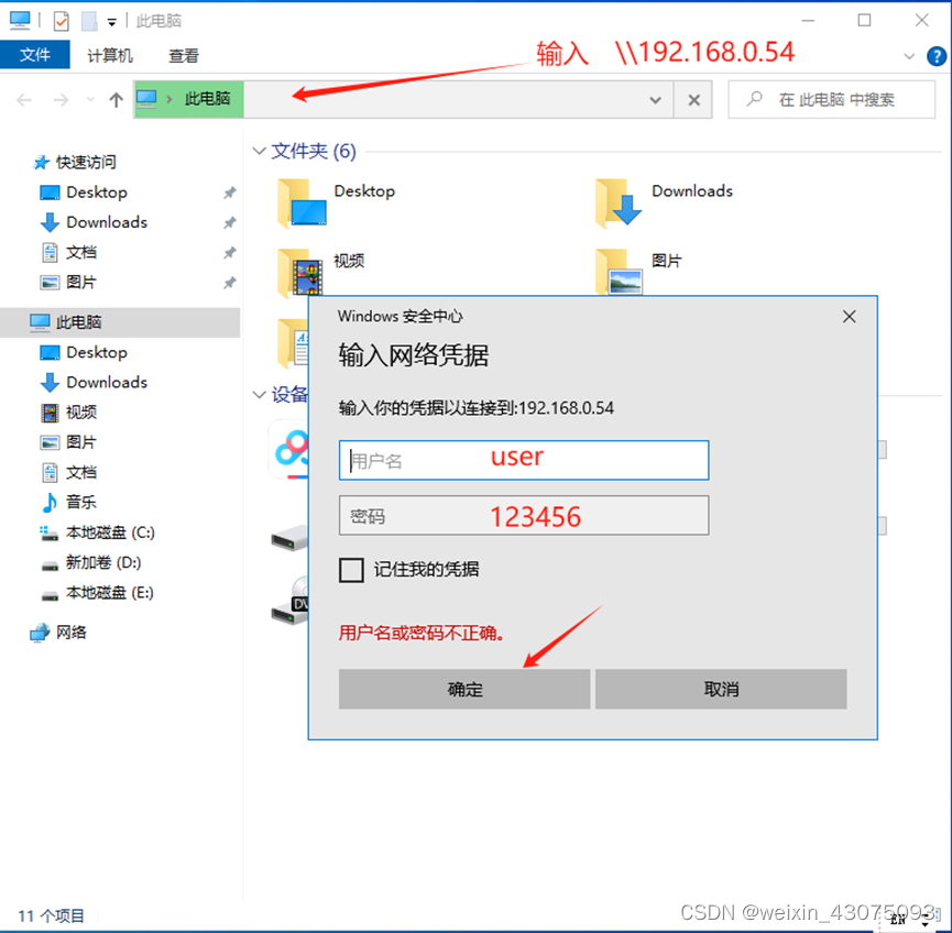
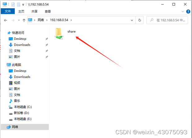
(2)输入之前配置好的共享用户名和密码user 123456后,确定,可以看到之前共享的文件夹了,share,如下图:
2、写入和读取测试
(1)写入正常,如下图:
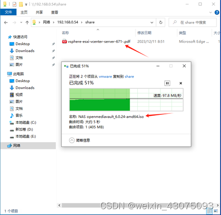
(2)读取正常,如下图:

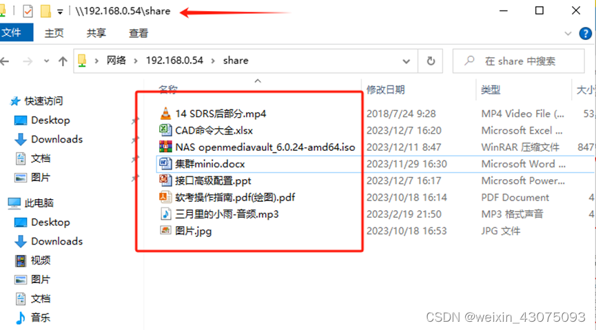
3、测试后在share共享文件夹下看到的内容如下:
四、外网访问测试:
(一)防火墙做端口映射
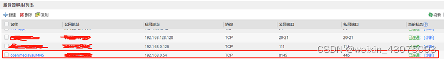
1、配置命令,将公网ip地址的8145端口映射到内网服务器192.168.0.54的445端口,命令如下(本例采用的是华为USG6630设备) :
nat server openmediavault445 protocol tcp global 公网IP地址x.x.x.x 8145 inside 192.168.0.54 445 no-reverse unr-route
2、查看映射结果,并测试连通性
(1)查看防火墙上的openmediavault服务器映射连通性,如下图:
(2)使用telnet 192.168.0.45 445命令,测试与内网服务器的连通性:
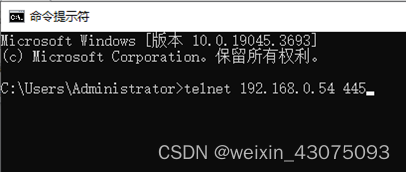
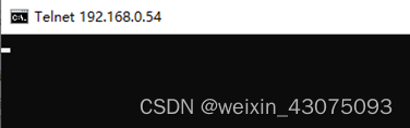
有光标闪烁,说明内网服务器上的445端口是开启的状态。
(二)防火墙配置安全策略, 使trust与dmz、untrust与dmz之间可互访
1、配置内网trust与DMZ区域服务器互通
ip address-set neiwang type object
address 0 192.168.0.0 mask 16
ip address-set server type object
address 1 192.168.0.0 mask 24
security-policy
rule name trustdmz
source-zone trust
destination-zone dmz
source-address address-set neiwang
action permit
rule name dmztrust
source-zone dmz
destination-zone trust
source-address address-set server
action permit
2、配置外网untrust与DMZ区域互通
security-policy
rule name untrustdmz
source-zone untrust
destination-zone dmz
destination-address address-set server
action permit
rule name dmzuntrust
source-zone dmz
destination-zone untrust
source-address address-set server
action permit
(三)防火墙上配置策略路由的情况下,内部使用外网地址访问服务器
1、策略路由:某些网段需要用专线访问外网(政务教育专网),某些网段可用拨号光纤访问外网(手机WIFI、电视、娱乐流量等)。
ip address-set 办公2 type object
address 0 192.168.175.0 mask 24
address 1 192.168.174.0 mask 24
address 2 192.168.29.0 mask 24
address 3 192.168.173.0 mask 24
address 4 192.168.162.0 mask 24
address 6 192.168.82.0 mask 24
address 10 192.168.83.0 mask 24
ip address-set jiaoxue type object
address 0 192.168.66.0 mask 24
address 1 192.168.67.0 mask 24
address 2 192.168.68.0 mask 24
address 3 192.168.69.0 mask 24
address 4 192.168.70.0 mask 24
address 5 192.168.71.0 mask 24
address 6 192.168.34.0 mask 24
address 7 192.168.35.0 mask 24
address 8 192.168.36.0 mask 24
address 9 192.168.72.0 mask 24
address 10 192.168.73.0 mask 24
address 11 192.168.102.0 mask 24
address 12 192.168.122.0 mask 24
address 13 192.168.115.0 mask 24
address 14 192.168.46.0 mask 24
address 15 192.168.47.0 mask 24
address 16 192.168.48.0 mask 24
address 17 192.168.49.0 mask 24
address 18 192.168.103.0 mask 24
ip address-set 商贸实训1 type object
description 6楼605-608
address 0 192.168.50.0 mask 24
address 1 192.168.51.0 mask 24
address 2 192.168.52.0 mask 24
address 3 192.168.53.0 mask 24
address 4 192.168.75.0 mask 24
address 5 192.168.54.0 mask 24
address 13 192.168.74.0 mask 24
ip address-set 商贸实训2 type object
address 0 192.168.76.0 mask 24
address 1 192.168.77.0 mask 24
address 2 192.168.155.0 mask 24
address 3 192.168.78.0 mask 24
address 4 192.168.79.0 mask 24
address 5 192.168.84.0 mask 24
address 6 192.168.81.0 mask 24
address 8 192.168.55.0 mask 24
address 9 192.168.56.0 mask 24
address 10 192.168.57.0 mask 24
policy-based-route
rule name 办公2
source-zone trust
source-address address-set 办公2
track ip-link test_200Mip121
action pbr egress-interface multi-interface
mode proportion-of-weight
add interface GigabitEthernet1/0/5 weight 3
add interface GigabitEthernet1/0/11
rule name 整班教学
source-zone trust
source-address address-set jiaoxue
action pbr egress-interface multi-interface
mode proportion-of-weight
add interface GigabitEthernet1/0/1
add interface GigabitEthernet1/0/2
add interface GigabitEthernet1/0/4
add interface GigabitEthernet1/0/6
rule name 商贸实训1
description 电商6-7楼121
source-zone trust
source-address address-set 商贸实训1
track ip-link test_200Mip121
action pbr egress-interface multi-interface
mode proportion-of-weight
add interface GigabitEthernet1/0/7 weight 2
add interface GigabitEthernet1/0/10
add interface GigabitEthernet1/0/5
rule name 商贸实训2
description 计算机2楼5楼183
source-zone trust
source-address address-set 商贸实训2
track ip-link test_100Mip183
action pbr egress-interface multi-interface
mode proportion-of-weight
add interface GigabitEthernet1/0/10
add interface GigabitEthernet1/0/7 weight 2
2、策略路由:指定所有内网段通过外网静态ip地址访问内网的服务器时,不做安全策略,并配置防火墙的回复数据包路径
ip address-set 179 type object
address 0 x.x.x.179 mask 32
ip address-set 133 type object
address 0 192.168.0.0 mask 24
address 1 192.168.128.0 mask 24
address 2 192.168.82.0 mask 24
address 3 192.168.129.0 mask 24
policy-based-route
rule name server-user
description 内网服务器通过外网回包到内网
source-zone trust
source-address address-set 179
source-address address-set 133
destination-address address-set 全部内网段
action no-pbr
rule name neiwang-server
description 内网通过外网访问内部服务器
source-zone trust
source-address address-set 全部内网段
destination-address address-set 179
destination-address address-set 133
action no-pbr
(4) Conversion configuration of external network access server IP address and port
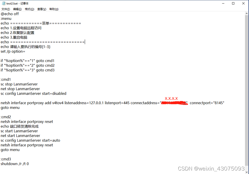
1. Batch file content:
@echo off
:menu
echomenu
echo 1. Set the computer to access
echo remotely 2. Restore the default configuration
echo 3. Restart the computer
echo ============================
echo Please enter Number to be executed [1-3]:
set /p option=
if “%option%”“1” goto cmd1
if “%option%”“2” goto cmd2
if “%option%”==“3” goto cmd3
:cmd1
sc stop LanmanServer
net stop LanmanServer
sc config LanmanServer start=disabled
netsh interface portproxy add v4tov4 listenaddress=127.0.0.1 listenport=445 connectaddress=“x.x.x.x” connectport=“8145”
goto menu
:cmd2
netsh interface portproxy reset
echo port forwarding clear completed
sc start LanmanServer
net start LanmanServer
sc config LanmanServer start=auto
netsh interface portproxy reset
goto menu
:cmd3
shutdown /r /t 0
Note: Change xxxx in the batch to your mapped external network IP address
2. When using the external network address to access the internal server on the internal network, or when accessing server resources on the external network, the execution steps are as follows:
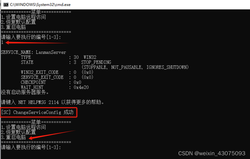
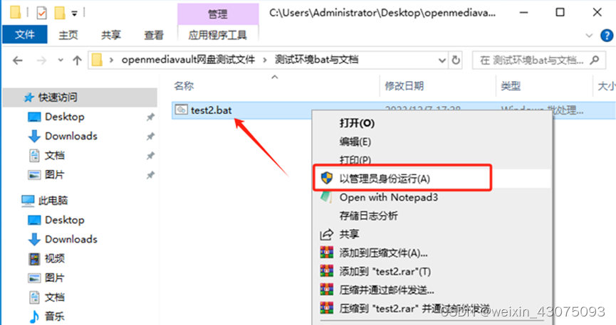
(1) Execute the batch test2.bat as an administrator
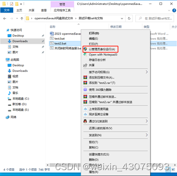
(2) Choose 1 to set up remote access to this computer, and then choose 3 to restart the computer.
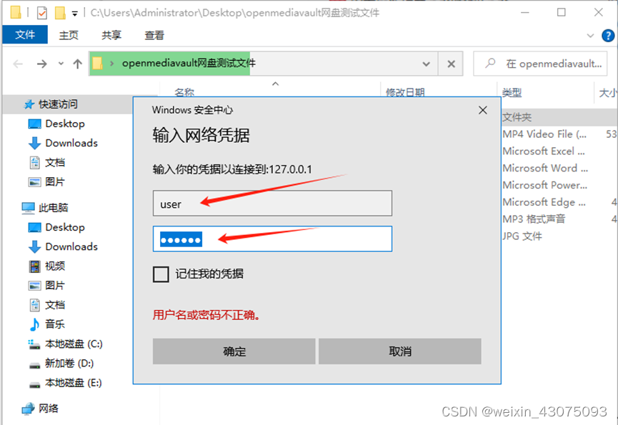
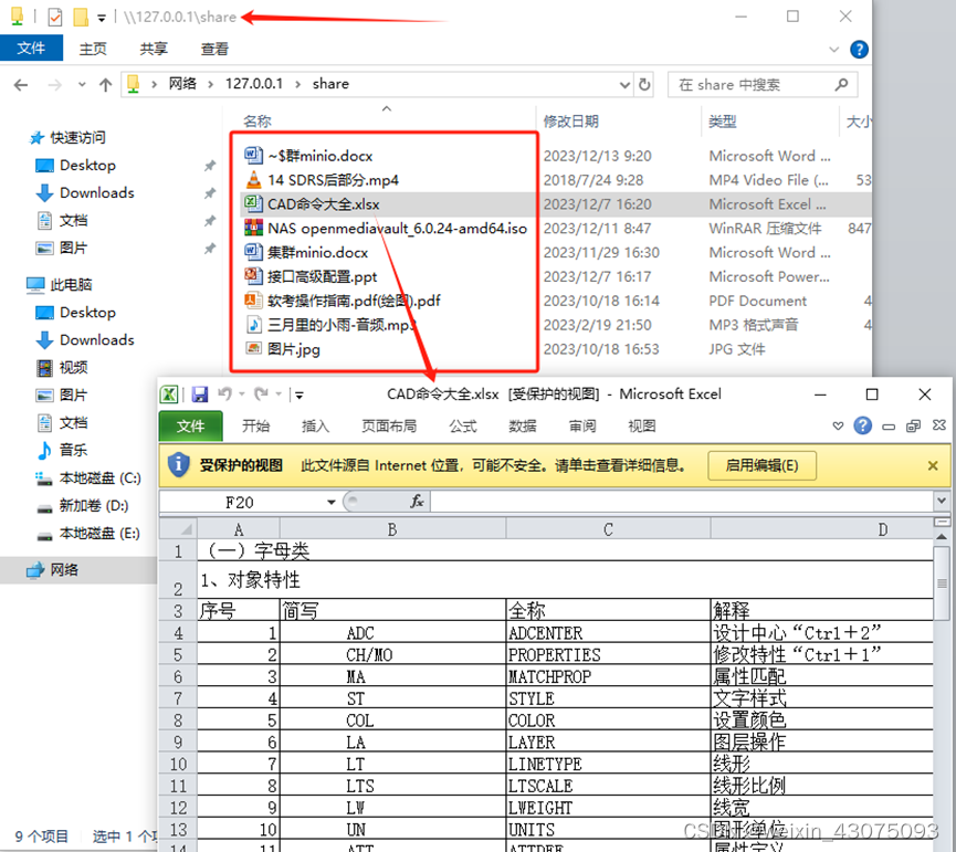
(3) Open the folder, enter \127.0.0.1 in the address bar, and press Enter, as shown below:
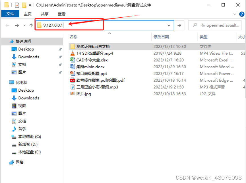
(4) Enter the username and password user 123456, as shown below:
(3) You can see the same content as that opened in the LAN, but the access address is different, as shown below:
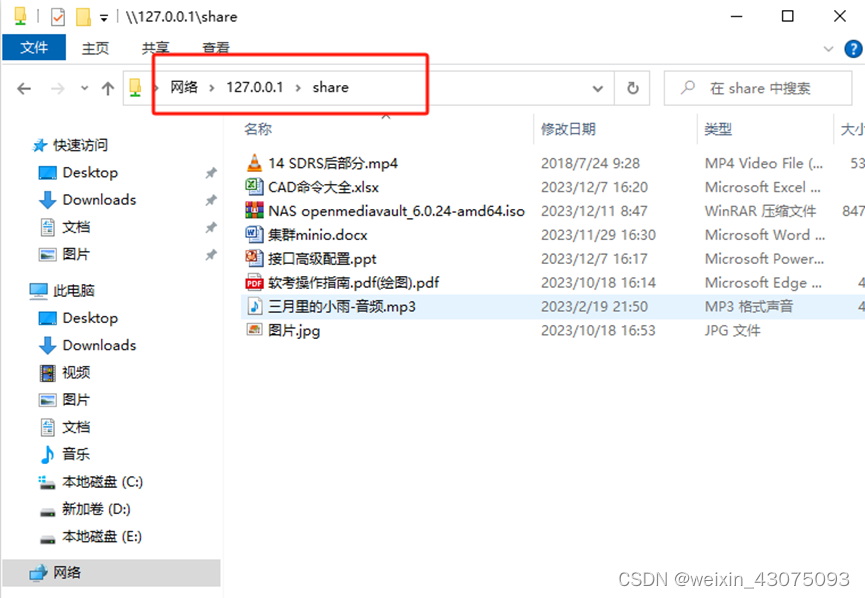
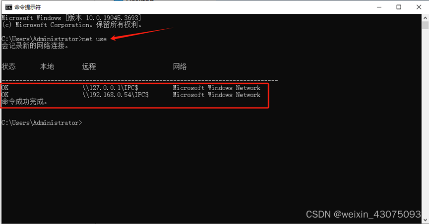
(4) At this time, when you use the command to view the existing shared mappings, you can see that there are 2. \192.168.0.54 is the mapping formed by intranet access, and the access of \127.0.0.1 is the external network port mapping completed by batch processing. .
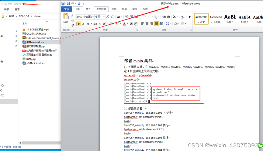
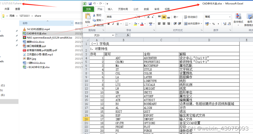
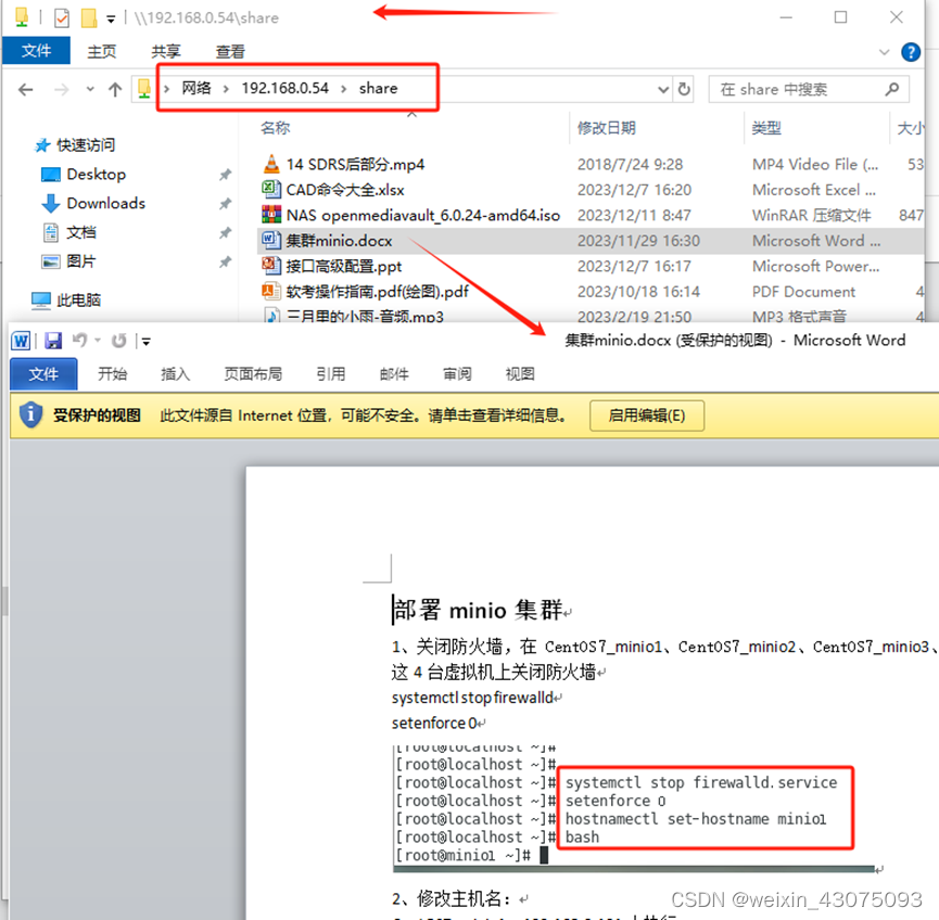
5. File opening test in shared server (word, excel, pptx, video, audio, picture, PDF document)
1. Word documents can be opened directly in the server shared folder, as shown below:
2. The excel spreadsheet can be opened directly in the server shared folder, as shown below:
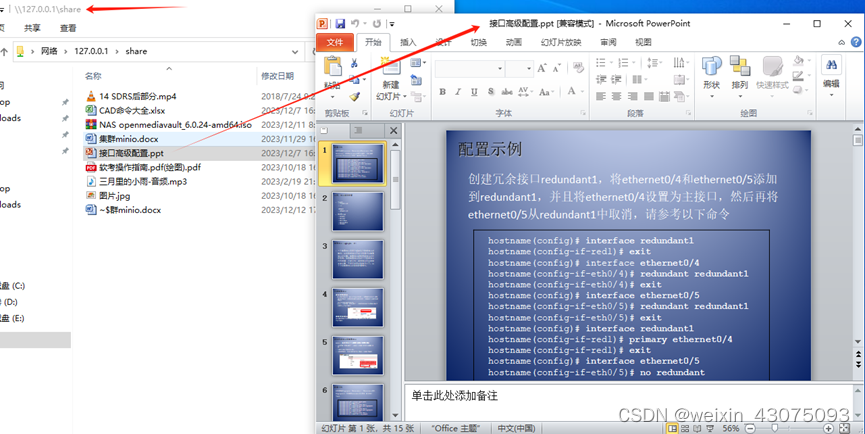
3. pptx presentations can be opened directly in the server shared folder, as shown below:
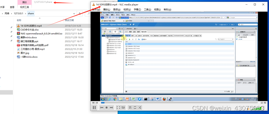
4. MP4 video files can be opened directly in the server shared folder, as shown below:
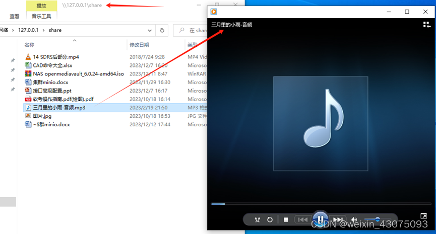
5. MP3 audio files can be opened directly in the server shared folder, as shown below:
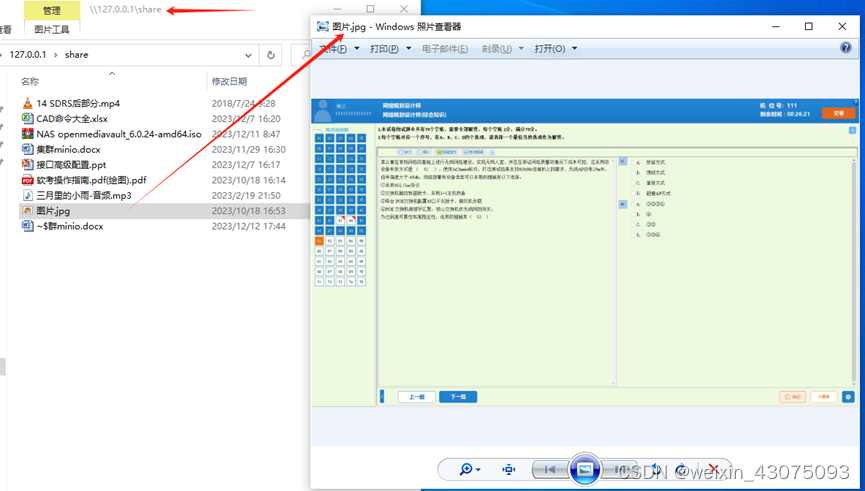
6. JPG image files can be opened directly in the server shared folder, as shown below:
7. PDF documents can be opened directly in the server shared folder, as shown below:
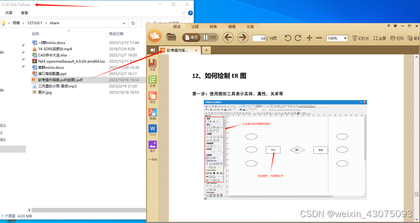
It can be seen that commonly used file types can be opened directly from the server's share and edited. It facilitates file sharing on the intranet and business trips on the extranet.
6. RAID volume and file system expansion
(1) RAID volume expansion
1. After shutdown, physical resources are flexibly adjusted.
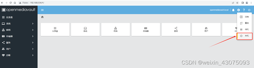
The shutdown methods are:
(1) Through the management side of the WEB browser, use the shutdown command, as shown below:
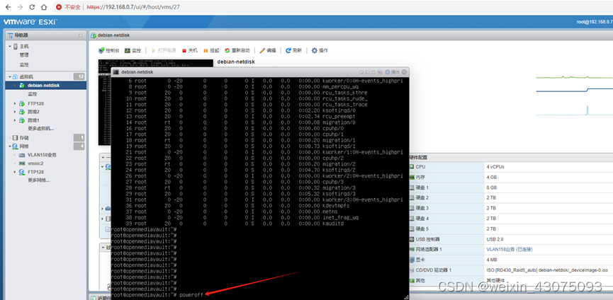
(2) In the command window of openmediavault, use the poweroff command to complete the shutdown, as shown below:
2. The vm server adjusts the physical resources, adds a new disk of 2TB to the virtual machine, and saves it.
3. After adding the disk, boot into the openmediavault system.
(2) Enter the backend management platform of openmediavault from the browser to implement memory expansion
1. Log in to openmediavault
2. After logging in, you can see that there are four 2TB disks, of which /dev/sde is the disk that was expanded after the recent adjustment of physical resources.
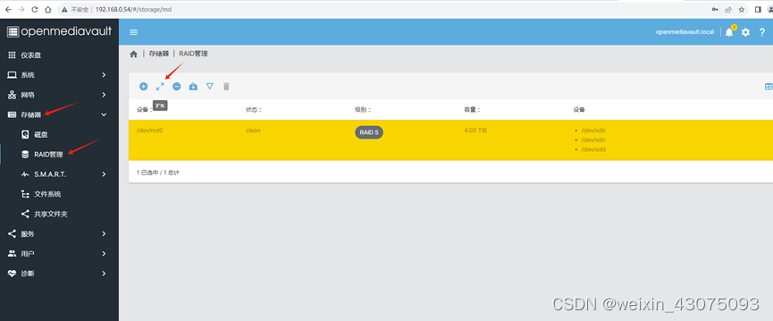
3. Before expansion, in RAID management, the total capacity after RAID5 is 4TB, which is composed of three 2TB disks, as shown below:
4. Implement expansion
(1) Storage, RAID management, select the original RAID5, and click Expand
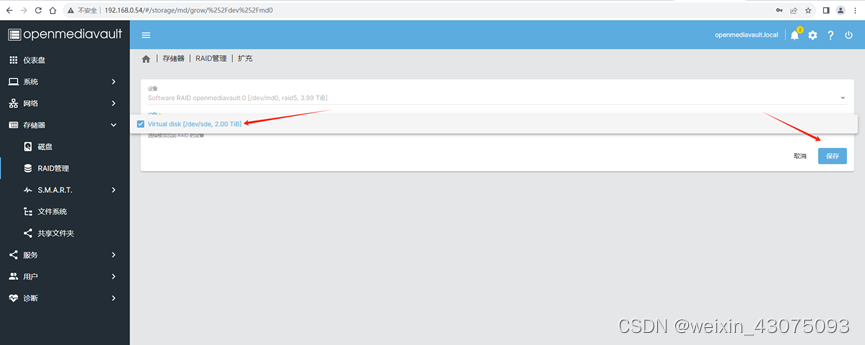
(2) Click Device*, select the expanded 2TB, and save it.
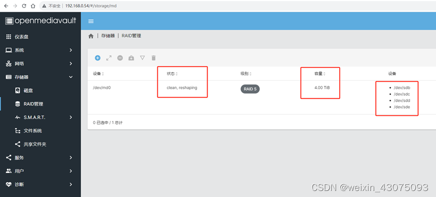
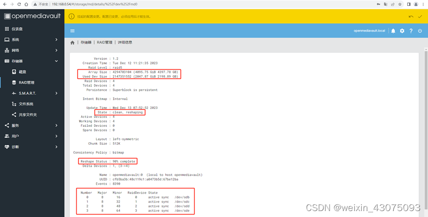
(3) At this time, notice that there are 4 disks, and the status has changed. There is reshaping next to clean and normal to reshape RAID5.
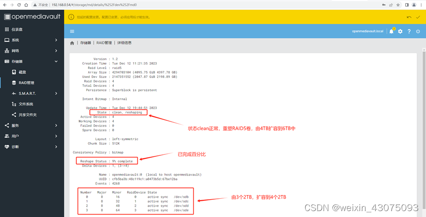
(4) You can see that 4 disks have appeared, 9% has been completed (about 1.5 hours), the status is clean and normal, and the RAID5 volume is being reshaped, as shown below:
(5) During the expansion process, the sharing of access servers is normal, indicating that the original data during the expansion process is not affected, as shown below:
(6) After about 14.5 hours, check the detailed information of the RAID volume to complete the reshaping of 91%, and continue to wait until it is completed to 100%. Click the check mark in the upper right corner, confirm, yes, to make the configuration effective, as shown below:
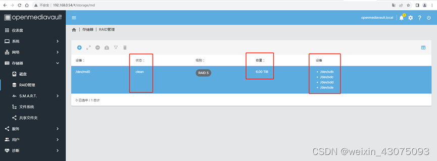
(7) After the RAID5 dynamic expansion is successful, you can see four 2TB disks forming a 6TB capacity RAID5, as shown below:
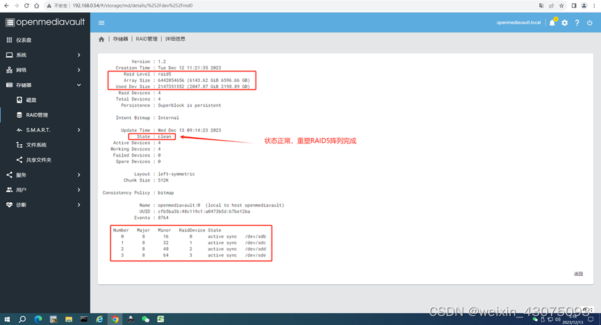
(8) View the detailed information of RAID, as shown below:
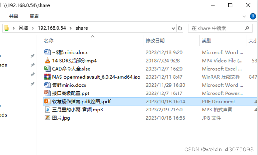
(9) After the RAID5 volume is expanded from 4TB to 6TB, when accessing \192.168.0.54, the data is still there, indicating that the lossless storage expansion has been successfully completed.
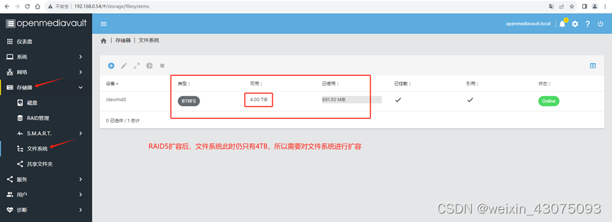
(3) File system expansion:
1. Check the RAID and file system:
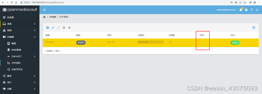
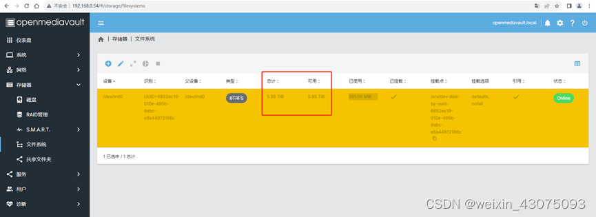
(1) After RAID5 is expanded to 6TB in openmediavault, the file system is still 4TB, as shown below:
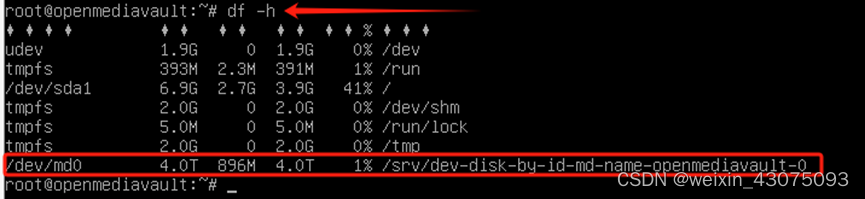
(2) In the debian linux terminal, run df –h to view, /dev/md0 is still 4.0TB
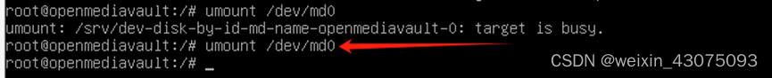
(3) Use the umount command to cancel the mount of /dev/md0, as shown below:
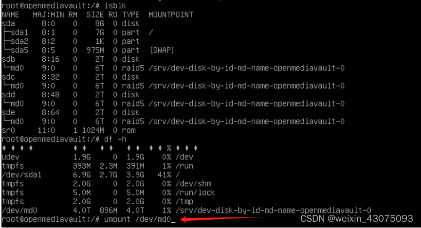
(4) Prompt that the target is busy, as shown below:

To solve the problem that the target is busy:
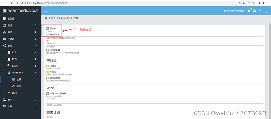
(1) Cancel the service startup of SMB/CIFS, as shown below:
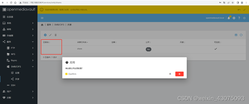
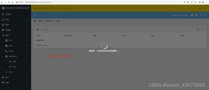
(2) Cancel the workgroup startup
(3) Delete the share in the memory
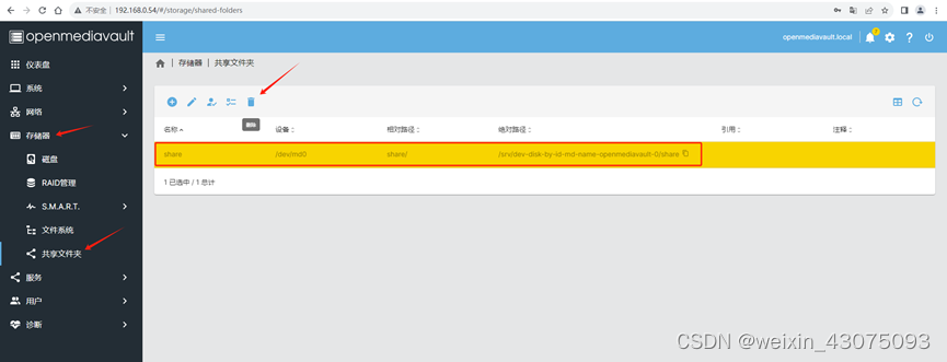
(4) At this time, the reference is no longer available, as shown below:
(5) Use umount /dev/md0 again. After canceling the mount, it will be normal, as shown below:
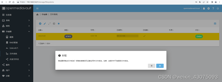
(6) Uninstall the originally mounted 4TB file system btrfs, as shown below:
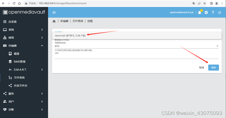
(7) Remount the dynamically expanded 6TB RAID5

(8) Select /dev/md0/[BTRFS 5.99TB] and save, as shown below:
(9) Confirm the mounted file system, as shown below:
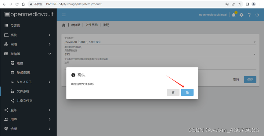
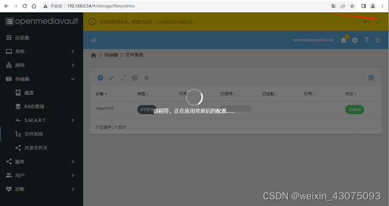
(10) Click the check mark in the upper right corner, confirm, yes, to confirm that the mount takes effect.
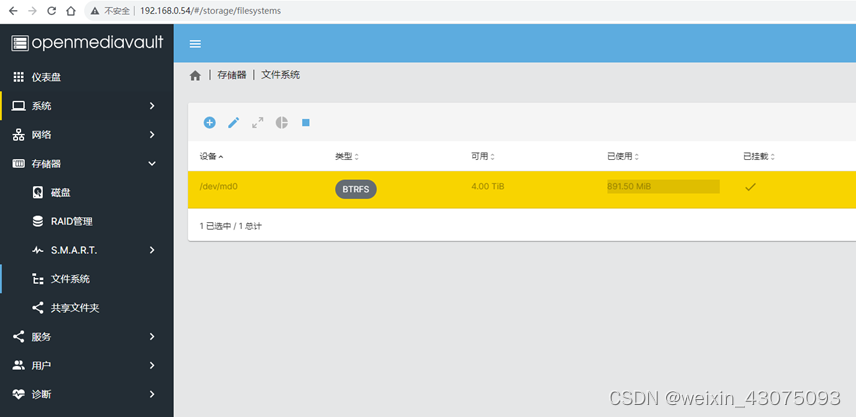
(11) At this time, only 4TB is still displayed (expansion is not available) as shown below:
2、文件系统扩容:
(1)使用命令给文件系统扩容2000GB
Btrfs filesystem resize +2000G /srv/dev-disk-by-uuid-6852ec19-010e-495b-9abc-e8a44972186c/

(2)使用命令查看文件系统扩容后的效果,可以看出从4TB扩容到了5.95TB
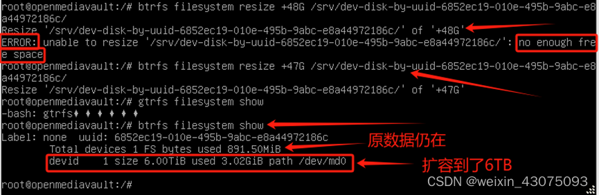
Btrfs filesystem show
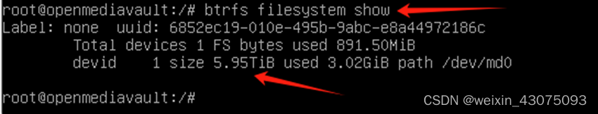
(3)回到openmediavault中查看文件系统时,很明显btrfs文件系统也已经扩容到了5.95TB
(4)继续扩容至6TB
当再添加48GB到挂载点/srv/dev-disk-by-uuid-6852ec19-010e-495b-9abc-e8a44972186c/时,提示没有足够的可用空间,减1GB,添加47GB扩容成功,如下图:
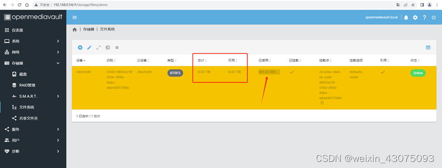
(6)再到openmediavault中查看文件系统时,很明显btrfs文件系统也已经扩容到了6TB
3、给出一些常用的btrfs文件系统操作命令,以供参考:
btrfs filesystem show #显示详细信息
btrfs filesystem df <挂载点> #已挂载分区使用状况
btrfs filesystem resize [+?G|max] <挂载点> #增减容量
btrfs filesystem defragment #碎片整理
btrfs device add <需要添加的设备> <挂载点>
btrfs device delete <需要添加的设备> <挂载点>
btrfs balance start <挂载点> #开始
-mconvert=raid[0,1,5,10] BTRFS_LABEL metadata
-dconvert=raid[0,1,5,10] BTRFS_LABEL data
#convert之类的选项,可以通过man文档中的filter字段查到
btrfs balance pause #暂停
btrfs balance status #状态
btrfs volume create 主卷下的挂载点
btrfs volume delete 主卷下的挂载点
btrfs subvolume list /media/btrfs/ 列出指定btrfs下的子卷及其id
btrfs-convert EXT4_DEVICEext4转换成btrfs
btrfs-convert -r BTRFS_DEVICE此前为ext4的btrfs转换回ext4
七、动态无损存储扩容后的访问验证:
(一)通过局域网访问存储系统\192.168.0.54,原数据正常可访问
(二)通过公网访问存储系统\127.0.0.1(已由批处理文件完成了公网ip地址与端口的转换过程),原数据正常可访问
1、以管理员身份运行批处理test2.bat,选择1,设置本电脑可远程访问服务器,如下图:
2、从命令菜单中选1,设置电脑远程访问,如下图:
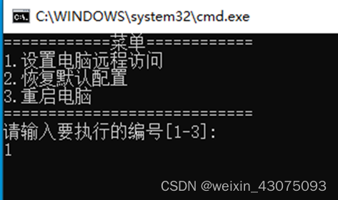
3、再选3重启电脑
4、打开文件夹后,在地址栏输入\127.0.0.1通过外网访问服务器如下:
Openmediavault自建的NAS系统无损原数据动态扩容,成功完成。不足之处敬请批评指正。本文至此结束