
Introduction
Compared with the past monolithic or SOA architecture, the components relied on to build microservice architecture have changed, so the ideas for analyzing and designing high-availability disaster recovery architecture solutions have also changed. This article discusses several common problems in the implementation of microservice architecture. Analysis of disaster recovery and high availability solutions.
about the author
Liu Guanjun is the head of Tencent Cloud Middleware Center Architecture Group and an expert engineer
with 15 years of experience in the IT industry. His first job was in the IBM China Laboratory, and he once served as the R&D Director of IBM mainframe middleware. Currently, he is an expert engineer at Tencent Cloud and the head of the middleware center architecture team. He is responsible for the middleware product center architect team and the pre-sales work of PaaS platform products. A total of 16 patent authorizations have been obtained. He has rich experience in transaction processing, web services, microservices, message queues and banking architecture, and has supported many large and medium-sized customers at home and abroad.
Overview
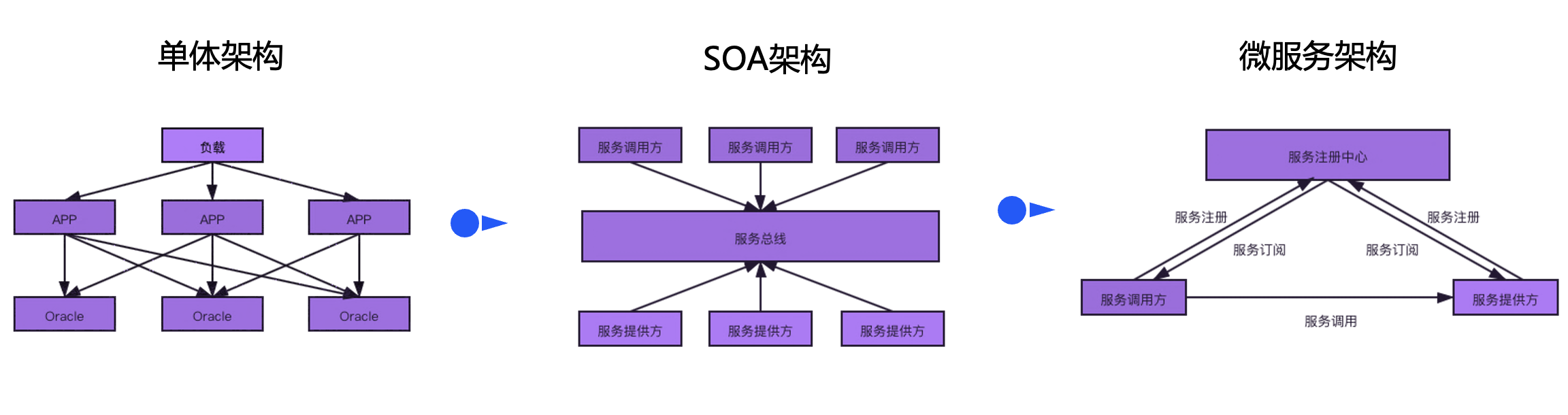
Compared with the SOA architecture, the microservice architecture uses a decentralized approach to organize business applications. Communication between services does not need to go through the bus, and the logic of service routing is sent to each microservice to complete itself. On the other hand, the microservice architecture is also inseparable from centralized components to implement functions such as service governance, application deployment, and monitoring. The design of high-availability disaster recovery solutions such as active-standby and multi-active in microservice scenarios requires comprehensive consideration.
Before analyzing a complex disaster recovery architecture, we should first clearly define the problem, dismantle the problem, decompose the sub-problem, and discuss it separately from different dimensions to obtain a clear conclusion. When we discuss high-availability modes such as active-standby and active-active, different high-availability modes have different meanings for components such as applications, databases, and registration centers, but each component is related to each other. In the author's opinion, a complete microservice architecture component contains three dimensions:
- Microservice management and control layer: Due to the complexity brought by distributed architecture, relevant distributed support components need to be introduced
- Application life cycle management component : Responsible for application release, rollback, elastic scaling, and failover. The microservice architecture has higher requirements for deployment and operation and maintenance capabilities, and requires the business to automate delivery facilities. These components have relatively little impact on business running time.
- Service governance component : Responsible for distributed governance capabilities such as service registration discovery, service configuration, and service routing. The most well-known component is the service registration center. The registration center is responsible for performing health checks on services and removing abnormal instances in a timely manner. Therefore, in the disaster recovery mode The network requirements are relatively high. If the network is unstable, it will easily lead to inaccurate health checks. Frequent large-scale service instance change notifications will affect system stability.
- Monitoring component : Responsible for collecting the three major components of observability: trace, log, and metrics. The bottom layer often uses ES or time series database. Since the amount of data requested by this component is relatively large, the cost of network traffic should be taken into consideration when planning and deploying.
-
Application layer: The application should be as stateless as possible to reduce the difficulty of deployment.
-
Data layer: At present, most applications use relational databases. The current technical level of relational databases cannot well support multiple instances and multiple writes, so we can only discuss the active and standby modes of the database. The key point is the automation of active and standby switching and data The delay of replication reduces the RTO and RPO of fault recovery respectively.
Main and backup in the same city
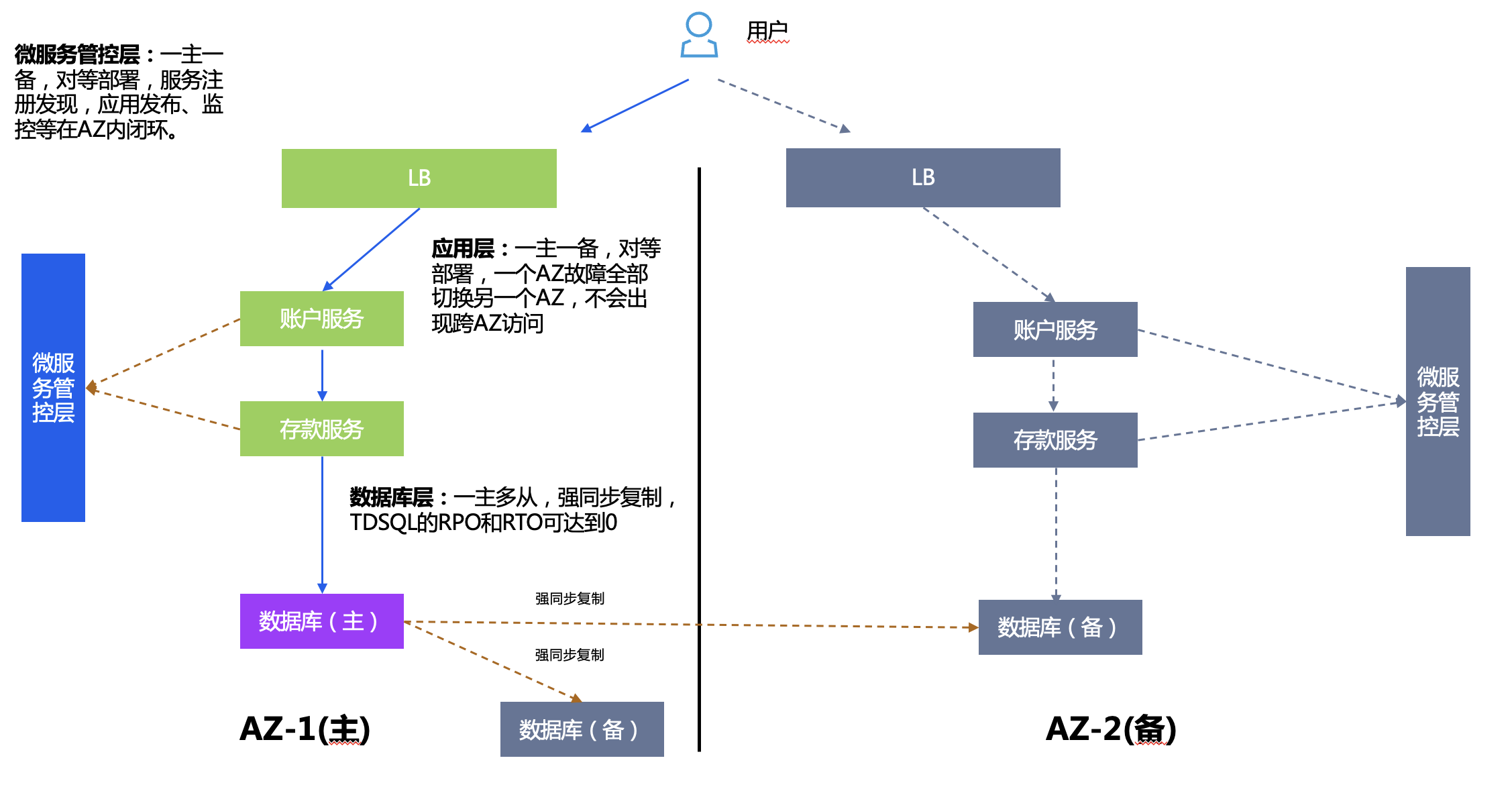
Active-Standby in the same city is often deployed in dual AZs, and the distance between AZs needs to meet regulatory requirements. In dual AZ, only one primary AZ provides services to the outside world, and the other standby AZ is used as backup, which often only requires the deployment of a small amount of resources.
Deployment plan:
- Microservice management and control layer: TSF has one master and one backup, service registration and discovery, application release, monitoring, etc. are all closed loop in AZ.
- Application layer: There is one master and one backup for applications. The backup center contains all logical applications in the main center, and the number of application copies can be reduced.
- Database layer: One master and multiple slaves, strong synchronous replication, RPO and RTO using TDSQL can reach 0, and applications can be switched without any awareness.
Application layer anomaly analysis
Analyze several abnormal scenarios at the application layer:
1. Single microservice instance failure: Microservices need to be deployed with multiple instances and can be fault-tolerant in a single AZ.
2. All instances of a certain microservice fail. There are two possible reasons.
- There is a problem with the code of the app itself: roll back the app or fix it.
- All physical instances of a certain microservice fail: Use IaaS layer node anti-affinity to deploy instances as dispersed among racks as possible.
3. All instances in the entire AZ fail: In this case, the backup AZ is enabled as a whole and user traffic is switched.
Microservice management and control layer anomaly analysis
The TSF microservice management and control layer can be divided into two levels:
- Release-time components: Mainly affect the release function of the application. Component failure affects the release and rollback of the application, but does not affect the operation of the application. TSF components themselves are stateless and can be deployed in multiple instances without affecting application operation. The bottom layer relies on the master-slave deployment of the MySQL database, which can be deployed across AZs independently to avoid single points of failure.
- Runtime components: divided into two levels
- Monitoring and logging components: All failures affect monitoring data collection, but do not affect application operation. The component itself is stateless and can be deployed in multiple instances. The underlying ES/Redis is a non-relational database and can be deployed in active/standby/sharding mode. It can be deployed across AZs independently to avoid single points of failure.
- Service Registration Center: The fault affects new service registration and configuration delivery. TSF has designed a caching mechanism locally in the application. When the registration center is unavailable, the application can still initiate inter-service calls. The components are deployed using consul cluster, with one master and multiple slaves mode.
For in-depth analysis of high availability on the TSF control end, please refer to the subsequent series of special articles.
Database layer anomaly analysis
Since the database is a single point, a single point of downtime may occur in a single AZ. In the event of a failure, it can be switched to the backup node in the same AZ or the same city. Similar to the one-master-multi-slave mode of TDSQL, TDSQL can also implement automatic IP failover. The application is unaware.
Live-active services in the same city
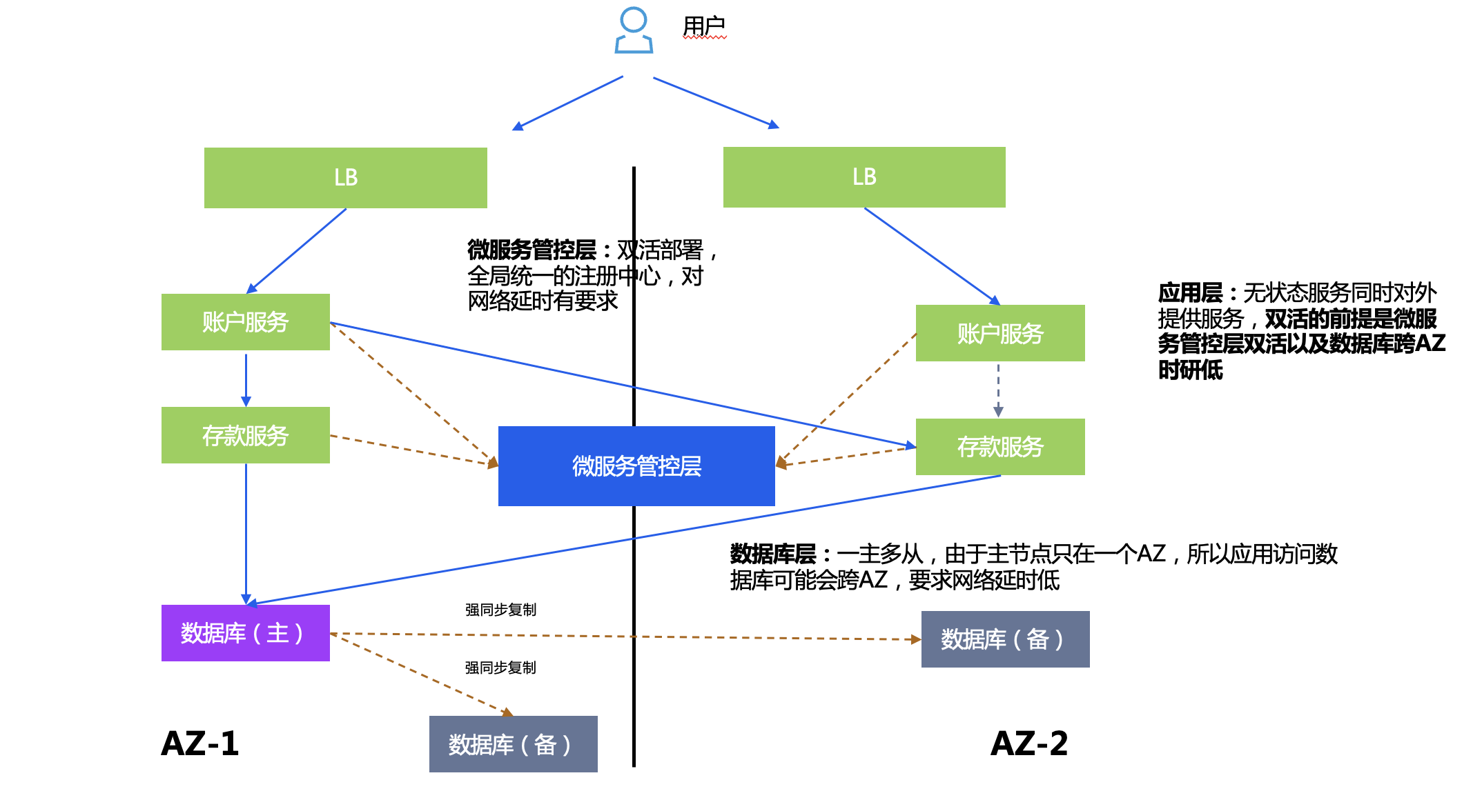
All the user's business systems run in two data centers at the same time, providing services to users at the same time. When an application system in one AZ has a problem, there is an application in another AZ to continue to provide services.
Deployment plan:
- Microservice management and control layer: TSF active-active deployment, has a globally unified registration center, and has requirements for network latency.
- Database layer: One master and multiple slaves. Since the master node is only in one AZ, applications accessing the database may cross AZs. Therefore, low network latency between AZs is required to reduce performance consumption caused by data skew.
- Application layer: Stateless services provide services to the outside world at the same time. The premise of active-active is that the microservice management and control layer is active-active and the database cross-AZ latency is low.
The high-availability deployment mode of the database layer is still one master and multiple slaves, and no exception analysis will be performed on the database layer later.
Application anomaly analysis
Analyze several abnormal scenarios at the application layer:
1. The entire AZ is down: Use technologies such as GSLB or cross-AZ LB to switch to another IP. At the same time, this layer of capabilities can achieve load balancing.
2. Disaster recovery for calls between microservices: TSF supports nearest routing within AZ, and cross-AZ calls when instances within AZ are unavailable.
Microservice management and control layer anomaly analysis
Currently, TSF implements automatic switching of components such as the registration center to another AZ based on cross-AZ VIPs (provided by customers or TCS/TCE). When a single AZ fails, the application automatically switches the control end of another AZ without any awareness.
Three centers in two places
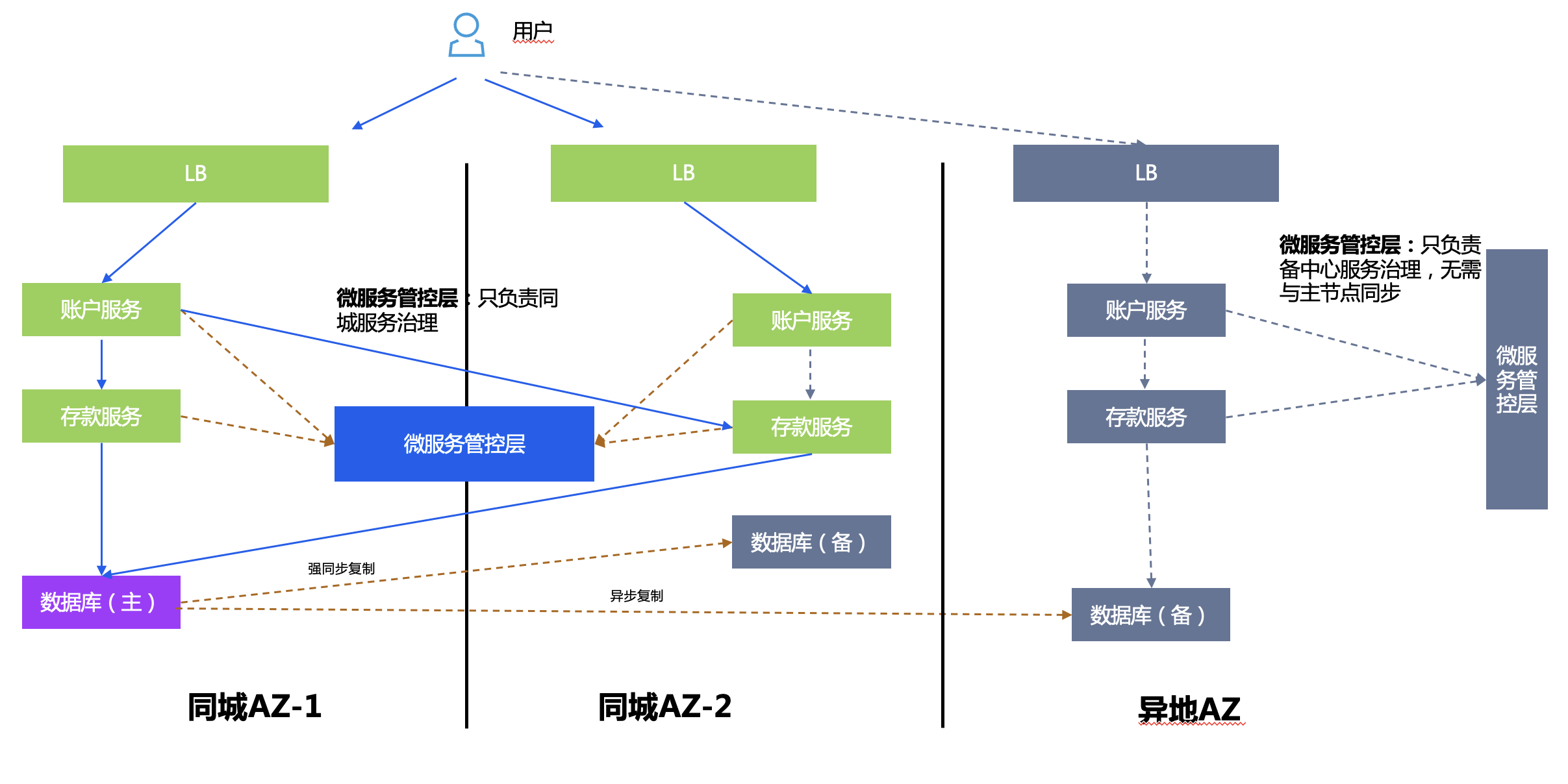
Three centers in two places are built on the basis of active-active in the same city + remote disaster recovery, and have both high availability and disaster backup capabilities. The remote disaster recovery center refers to the establishment of a backup disaster recovery center in a remote city for dual centers Data backup. When the dual centers fail due to natural disasters or other reasons, the remote disaster recovery center can use the backup data to restore the business.
The overall architecture is a combination of active-active and active-standby in the same city.
Deployment plan:
- Microservice management and control layer: active-active deployment in the same city, disaster recovery in remote locations, their respective data does not need to be synchronized, and they are only responsible for their own service management and control.
- Database layer: one master and multiple slaves, TDSQL strong synchronization in the same city, and asynchronous replication in different places.
- Application layer: Stateless service provides services to the outside world at the same time. After the main center fails, the ingress route is switched to the remote backup center.
Live more in a different place
The premise of multi-activity in different places is that the architecture can realize three centers in two places, and horizontal sharding is done at the database level, and business applications are bound to database shards in groups. Multi-active in remote locations can reduce the scope of faults to a single shard and reduce database complexity. This architecture is generally used for national banks/insurance companies with very large amounts of data.
The solutions are divided into two types: remote mutual backup and unitization, which are introduced separately below.
Remote preparation
The database level is horizontally split into two instance shards, for example, it can be split into north and south by region.
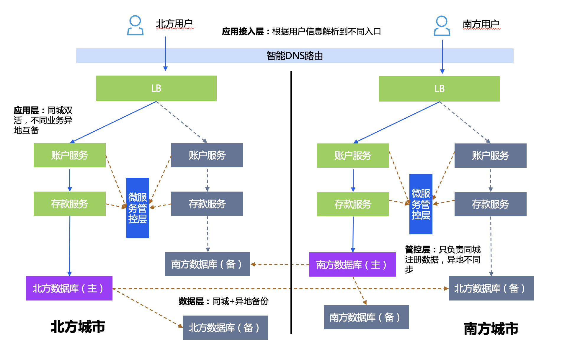
Deployment plan:
- Microservice management and control layer: serving active-active services in the same city, but not interoperable in different places.
- Application layer: Applications with different data shards are active-active in remote locations, applications with the same data shards are active-active in the same city, and remote disaster recovery is provided.
- Database layer: Data sharding has one master and multiple slaves, and different shards are replicated in different locations.
Disaster recovery switching strategy: If the entire southern city fails, DNS will be done at the entrance to switch the access IP of southern users to the north.
unitization
Generally, if the amount of data is too large and simply using database sharding mode cannot solve the problem, you can consider using a unitized architecture. First, clarify the definition of a unit. A unit is a logical binding of a group of computing resources and a group of data resources. The key points of the design include:
1. Sharding: Consider volume and business, select a partitioning strategy, and try to avoid cross-unit calls.
2. Deployment unit design: consider disaster recovery design, bind units to database shards, have active-active units in the same city, and deploy disaster recovery units in remote locations.
3. Routing: TSF provides the ability to calculate unitized rules at the gateway entrance or service entrance, dye the requests, and route subsequent requests to the same unit according to conditions, and call them through the gateway when crossing units.

Deployment plan:
- Microservice management and control layer: Because the gateway may be unitized, a global service registration center is required.
- Application layer: Each region contains all unit shards. Applications with different data shards can be active-active in different places. Applications with the same data shard can be active-active in the same city and have remote disaster recovery.
- Database layer: Data sharding has one master and multiple slaves, and different shards are replicated in different locations.
Unit exception analysis:
- Entire region failover: The entire traffic is switched to another region.
- Failover of a single unit in a region: Apart from problems with the application code itself, units are physically deployed in multiple centers in the same city. It is basically impossible for all units in a city to go down.
Multiple activities in remote locations based on unitization
Clarification of the concept of multiple lives in different places:
- Origin of the problem: Another core consideration in the unitized architecture is to facilitate the realization of multiple activities in different places. There is a widely criticized problem in the traditional local active-active and remote disaster recovery architecture, which is that the remote disaster recovery resources do not actually serve the business most of the time. After they are purchased and deployed, they remain idle for a long time, like a warrior who has not been in battle for a long time. It's a waste of the country's military pay. In order to better improve the utilization of resources, many customers, especially financial customers, are further pursuing a multi-active structure in different locations, so that resources in remote locations can share part of the traffic and process business normally.
- Here we should pay attention to the correct understanding of the concept of living in different places. Multi-activity in different places does not mean that all services (including all applications and all data) can live in region A and region B at the same time (the two places are hundreds of kilometers apart and meet disaster recovery regulatory requirements); rather, it means that some businesses Processing is done in region A, and part of it is processed in region B. No region is completely idle. Because the former approach is too expensive both in terms of technology and economic cost.
- Unitization supports multi-activity in different locations: Under the unitization architecture, since the data is fragmented and processed in units, different units are processed in different regions. Naturally, the above-mentioned goal of multiple activities in different places and full utilization of machine resources is achieved. While each region handles business in separate units, it also serves as a disaster recovery center to provide remote disaster recovery capabilities for applications and data to other remote units.
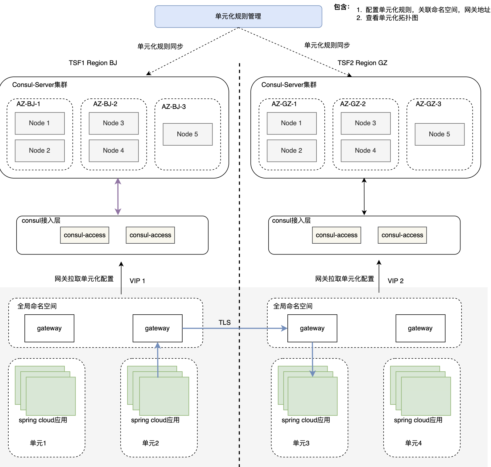
At present, TSF products have achieved unitization capabilities. At the same time, in order to achieve the demand of unitization and remote multi-activity, TSF has implemented the ability of cross-regional multi-cluster mutual discovery and mutual access in the latest version, as shown in the figure below.
- The implementation principle is not based on a cross-regional global registration center, because the current registration center of TSF is still Consul, and the Consul cluster is in CP mode. The CP mode has high requirements on the delay of information synchronization, and the Consul cluster can only be deployed with multi-node high availability in the same city. , cannot be deployed remotely. Therefore, the current remote access of TSF adopts the unit gateway addressing mode. The unit gateway looks for another unit gateway where the remote service is located, and then pulls it to the Consul registration center of the cluster based on Consul Access (stateless front-end layer). Get service nodes to achieve cross-regional service access. The advantage of forwarding through the gateway is that the unit is well sealed, the access link is clear, and problems can be traced easily; the disadvantage is that the number of service jumps is increased, and the response time will be increased.
- In the future, the TSF registration center will be integrated into the Polaris registration center, which is an AP mode registration center based on a database master-slave method for storing information, and can better serve as a cross-regional global registration center.
Summarize
The above is based on the microservice architecture and analyzes the high-availability solutions from each layer. The design of the high-availability architecture of each layer is complementary to each other. The lack of capabilities of any layer under each high-availability solution may not achieve the desired goal. . TSF has implemented various high-availability architectures introduced above in customers in various industries in the past, and has accumulated rich experience. In general, architectural design is a matter of making trade-offs. There is no perfect solution. On the one hand, the principle of simplicity should be followed. The simpler the architectural design, the easier it is to implement, the lower the operation and maintenance complexity, and the lower the cost. On the other hand, it should be based on the actual situation. Demands, such as regulatory requirements, deployment status, business data volume, etc., are combined with objective conditions to select the appropriate solution.
Lei Jun announced the complete system architecture of Xiaomi's ThePaper OS, saying that the bottom layer has been completely restructured. Yuque announced the cause of the failure and repair process on October 23. Microsoft CEO Nadella: Abandoning Windows Phone and mobile business was a wrong decision. Both Java 11 and Java 17 usage rates exceeded Java 8 Hugging Face was restricted from accessing. The Yuque network outage lasted for about 10 hours and has now returned to normal. Oracle launched Java development extensions for Visual Studio Code . The National Data Administration officially unveiled Musk: Donate 1 billion if Wikipedia is renamed "Weiji Encyclopedia" USDMySQL 8.2.0 GA