In previous issues, Xiao Yi introduced the I/O module of the Classic AUTOSAR topic to everyone . I believe that those who have seen it already have a basic understanding of the I/O module of Classic AUTOSAR. In this issue, I will introduce to you the "AUTOSAR Module" Diagnostic Module", which is very rich in content and will be launched in two phases.
Table of contents
1 Overview
2.DCM
3.DEM
4.FIM
5 Conclusion
01Overview _
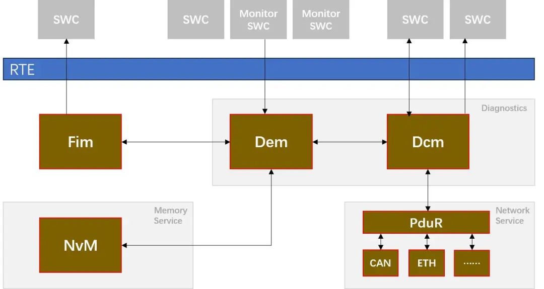
In order to monitor the operating status of the vehicle during its life cycle, vehicle diagnostic technology emerged as the times require. AUTOSAR's diagnostic module enables remote or local diagnosis of vehicle control systems. It provides a series of specifications, including Diagnostics Communication Manager (DCM), Diagnostic Event Manager (DEM) and Function Inhibition Manager (FIM), to achieve complete vehicle diagnostic functions.
02 DCM
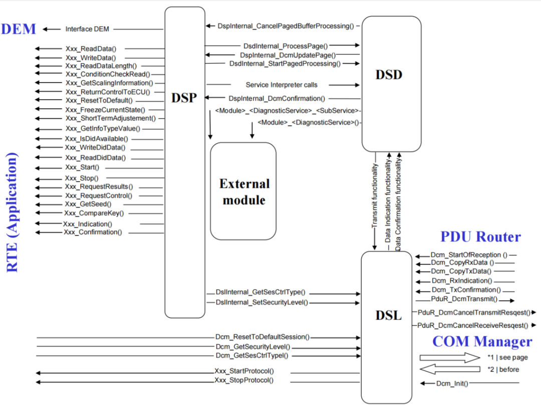
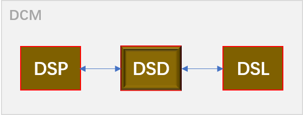
DCM (Diagnostics Communication Manager) is the underlying diagnostic communication manager module, which is used to manage the entire diagnostic communication process and process diagnostic data flow. The function of the DCM module is implemented by three sub-modules, namely DSL (Diagnostic Session layer) is used to process diagnostic requests and diagnostic response data, and monitor the timing of diagnosis; DSD (Diagnostic Service Dispatcher) is used to process diagnostic data flow, and DSP (Diagnostic Service Processing) is used to distribute different diagnostic service requests.
2-1 DSL
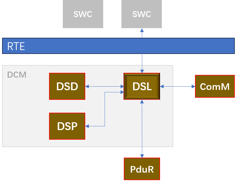
Interaction of DSL with other modules
Interact with the PduR module:
● PduR module provides diagnostic request data input to DSL
● The DSL module outputs diagnostic response data to the PduR module
Interacting with the DSD submodule:
● The DSL submodule notifies the DSD submodule about the incoming request and provides the data
● The DSD submodule will trigger the output of the diagnostic response
Interacting with the SWC/DSP module:
● DSL submodule provides access to security and session state
Interacting with the ComM module:
● The DSL sub-module ensures the communication behavior required by the ComM module
DSL module functions
Diagnostic request handling
● Forward requests from the PduR module to the DSD submodule. The DSL submodule should call Dcm_TpRxIndication and return the parameter Result = E_OK before forwarding the received data to the DSD submodule.
● Tester remains online ("keep valid logic"). The "Tester online" command can be sent by the Tester via physical request/response, i.e. "keep alive logic" defined in ISO14229-1 [1]
Diagnostic response handling
The DSD submodule shall request the DSL submodule for transmission of diagnostic response data.
● Forward the diagnostic response data incoming from the DSD submodule to the PduR module. The DSD submodule shall request the DSL submodule for transmission of diagnostic response data
● Guarantee the response time to the tester. If the application (or DSP submodule) is able to perform the requested diagnostic task, but requires additional time to complete the task and prepare a response, the DSL submodule should send NRC0x78 (Response Pending) when the response time is reached
● Support periodic transmission mode. The UDS service periodically reads data through ReadDataByPeriodicIdentifier (0x2A); Periodic Transmission communication can only be performed in Full Communication Mode.
● Support event-based transmission mode. The UDS service requests the ECU to start/pause transmission diagnostic response through ResponseOnEvent (0x86)
● Support segmented response
Security level processing
Manage security levels. The DSL submodule should save the level of the currently active security level. In order to access the Security Level, the DSL submodule provides two interfaces:
① Get the current security level: Dcm_GetSecurityLevel
② Set the current security level: DslInternal_SetSecurityLevel
Session state handling
● Manage session state. The DSL submodule should save the status of the current active session. In order to obtain the current session status, the DSL module provides two interfaces:
① Get the current session status: Dcm_GetSesCtrlType
② Set up a new session: DslInternal_SetSesCtrlType()
● Keep track of currently running non-default sessions. When a non-default session is active, and the session timeout (S3Server) is reached, the DSL submodule should reset to the default session state ("Default Session", 0x01)
● Allow modification of timing parameters. Including P2ServerMin, P2ServerMax, P2*ServerMin, P2*ServerMax, S3Server
Diagnostic protocol processing
● Handle different diagnostic scenarios
● Manage resources
Communication mode processing
● Communication requirement processing (Full- / Silent- / No Communication)
● Instructions active / inactive diagnostic
● Enable/disable various diagnostic transmissions
2.2 DSD
Interaction of DSD with other modules
Interact with the DSL module:
| Data transfer direction |
explain |
| Two-way |
Exchange diagnostic information (receive/transmit) |
| DSD→DSL |
Get the latest diagnostic session and the latest security level |
| DSL→DSD |
Diagnostic message transmission confirmation |
Interaction with DSP module:
| Data transfer direction |
explain |
| DSD→DSP |
Delegate diagnostic request processing Diagnostic message transmission confirmation |
| DSP→DSD |
Processing completed message notification |
DSD module functions
Support checking diagnostic service identifiers and adapting diagnostic messages
If a new diagnostic message is recognized, the DSL submodule shall trigger the DSD submodule. The DSD submodule will perform corresponding processing by analyzing the diagnostic service identifier contained in the received diagnostic message.
suppressPosRspMsgIndicationBit
If "suppressPosRspMsgIndicationBit" is true, the DSD submodule shall not send a positive response message. Only available if the service has sub-features.
Verification function
Before executing received diagnostic services, DSD performs a set of verifications. Only when all verifications are successfully passed will DSD accept the service. Verification items include:
● Verify manufacturer license
● Verify SID
● Verify service access control under current authentication status
● Validation of diagnostic sessions
● Verify service security access levels
● Verify supplier licenses
● Pattern rules for validating service IDs
Check format and sub-function support:
Before executing the requested command, the DSD submodule checks whether a specific subfunction is supported. If the subservice is not configured, the DSD should send a negative response NRC: 0x12 (subfunction not supported). The DSD submodule will check the minimum message length before executing the requested command.
Assign diagnostic information to DSP submodules
The DSD submodule collects the executable functions of the diagnostic service identifier newly received by the DSP submodule and calls the corresponding DSP service interpreter.
Assemble Positive/Negative Response:
When the DSP sub-module has completed the execution of the requested diagnostic service, the DSD sub-module shall assemble the diagnostic response message.
Start transfer
The DSD submodule shall forward diagnostic response information to the DSL submodule.
2.3 DSP
Overview
When receiving a call request from the DSD submodule, the DSP always performs the following basic processing steps:
● Analyze received diagnostic request messages
● Check the format and whether the carried sub-function is supported
● Obtain data or perform required function calls on DEM, SW-Cs or other BSW modules
DSP module function
Check format and subfunction support
The DSP submodule will check for appropriate message length and structure before executing the requested command. When an analysis diagnostic request is in the wrong format or length, the DSP submodule should trigger a negative response with NRC: 0x13 (message length error or invalid format).
Assemble diagnostic response message
The DSP submodule shall assemble the response message excluding the response service identifier and determine the length of the response message.
Negative response code handling
When there is no specific NRC, if the API call execution service does not return OK, the DSP submodule should return NRC: 0x10 for a negative response (general rejection). If the request message contains unsupported parameters, the DSP submodule should trigger a negative response with NRC: 0x31 (request out of range).
Diagnostic mode management
● DcmDiagnosticSessionControl (service 0x10)
● DcmEcuReset (partly service 0x11)
● DcmSecurityAccess (service 0x27)
● DcmModeRapidPowerShutDown (partly service 0x11)
● DcmCommunicationControl_. (service
0x28)
● DcmControlDTCSetting (service 0x85)
● DcmResponseOnEvent_(service 0x86)
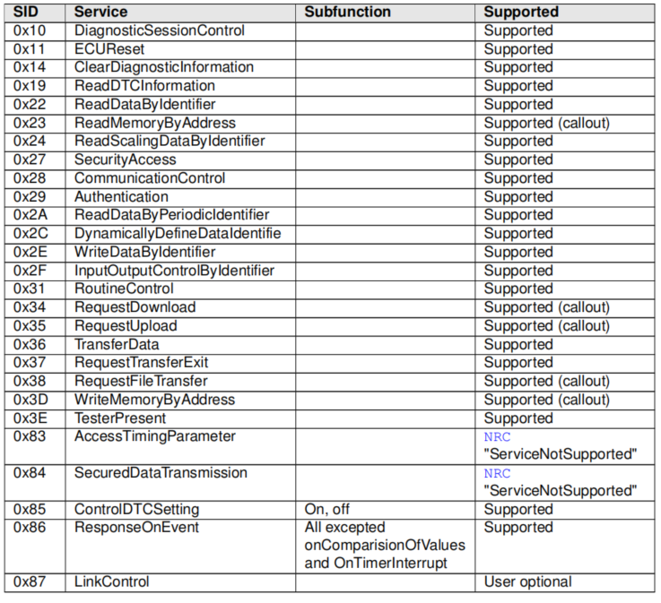
Support UDS service
The following table defines the UDS services supported by DCM:
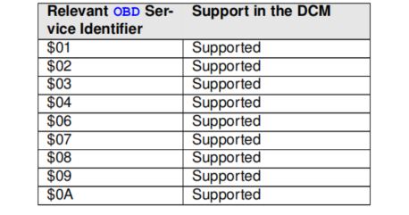
Support OBD service
The following table defines the OBD services supported by DCM:
2.4 DID Configuration
The configuration of Dcm contains a list of supported DIDs, which can be configured in two ways:
● Individual DID configuration: Each DataElement needs to be configured with a separate connection to access data (read, write and control)
● DID range configuration: used to handle DIDs that are uniformly located in a PortConnection and have the same behavior in SWC