Table of contents
3.1. Overview of data link layer
Hosts, routers, etc. in the network must implement the data link layer
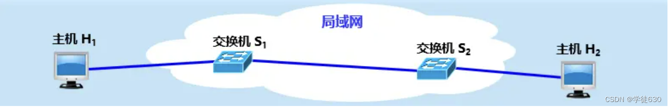
Hosts, switches, etc. in the LAN must implement the data link layer
Looking at the flow of data from a hierarchical perspective
Observe the flow of frames only from the data link layer
Channels used by the data link layer
Reliable transmission of edits
3.2. Encapsulation into frames
Solve the problem of transparent transmission
The length of the data part of the frame
Cyclic Redundancy Check CRC (Cyclic Redundancy Check)
Stop-wait protocol channel utilization
Why use the fallback N frame protocol?
Select retransmission protocol SR
3.5. Point-to-Point Protocol PPP
3.6. Media access control (media access control) - broadcast channel
Frequency Division Multiplexing FDM (Frequency Division Multiplexing)
Time Division Multiplexing TDM (Time Division Multiplexing)
Wavelength Division Multiplexing WDM (Wavelength Division Multiplexing)
Code Division Multiplexing CDM (Code Division Multiplexing)
Random access (CSMA/CD protocol)
CSMA/CD protocol working - contention period (collision window)
CSMA/CD protocol working - minimum frame length
CSMA/CD protocol working - maximum frame length
CSMA/CD protocol working - truncated binary exponential backoff algorithm
CSMA/CD Protocol Operation - Channel Utilization
CSMA/CD protocol work - frame reception process
Important features of the CSMA/CD protocol
Random access (CSMA/CA protocol)
Why does wireless LAN use CSMA/CA protocol?
InterFrame Space IFS (InterFrame Space)
How the CSMA/CA protocol works
When to use the backoff algorithm
Backoff algorithm of CSMA/CA protocol
Channel reservation and virtual carrier monitoring of CSMA/CA protocol
3.7. MAC address, IP address and ARP protocol
The data link layer of the broadcast channel must use an address (MAC)
MAC address format of IEEE 802 LAN
IEEE 802 LAN MAC address sending sequence
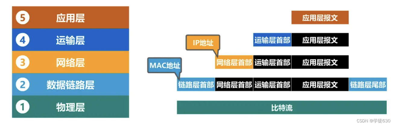
Looking at IP address and MAC address from the perspective of network architecture
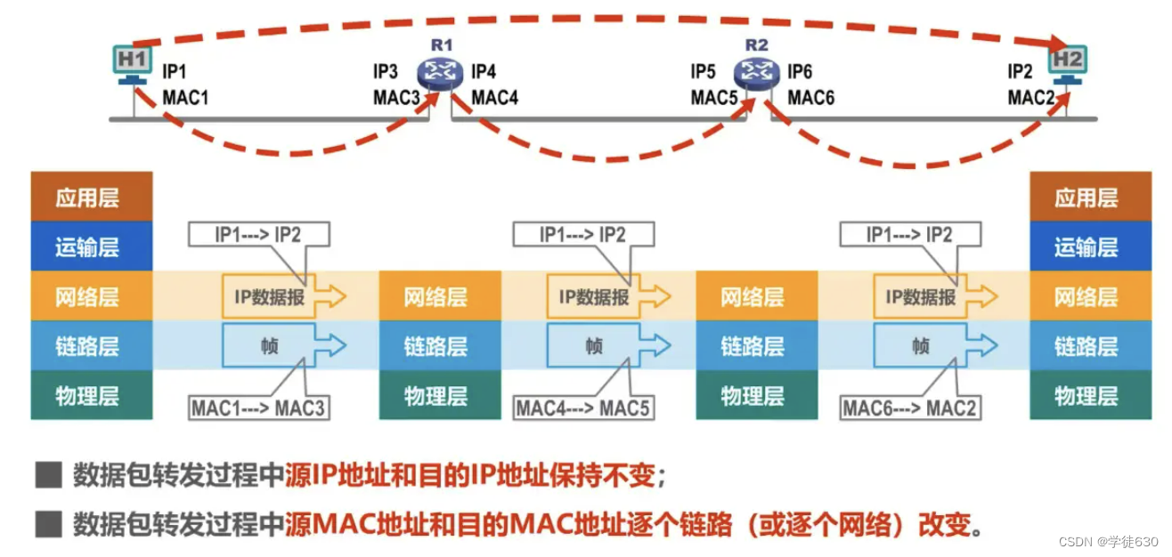
Changes in IP addresses and MAC addresses during data packet forwarding
The difference between dynamic and static
The ARP protocol can only be used on a link or a network and cannot be used across networks.
3.8. The difference between hub and switch
Hub - extends Ethernet at the physical layer
Hub HUB extends Ethernet at the physical layer
Ethernet switches - extending Ethernet at the data link layer
The difference between hub HUB and switch SWITCH
The difference between hub extended Ethernet and switch extended Ethernet
3.9. Ethernet switch self-learning and frame forwarding process
Example of self-learning and forwarding frames
3.10. Spanning Tree Protocol STP of Ethernet switches
How to improve the reliability of Ethernet
How to split broadcast domains
Implementation mechanism of virtual LAN VLAN
3.1. Overview of data link layer
Overview
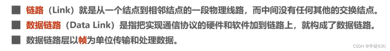
A link is a physical line from one node to an adjacent node. A data link adds some necessary hardware (such as network adapter) and software (such as protocol implementation) to the link.
Hosts, routers, etc. in the network must implement the data link layer

Hosts, switches, etc. in the LAN must implement the data link layer
Looking at the flow of data from a hierarchical perspective
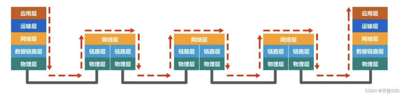
Observe the flow of frames only from the data link layer

The network passed from host H1 to host H2 can be of many different types.
Note: Different link layers may use different data link layer protocols
Channels used by the data link layer
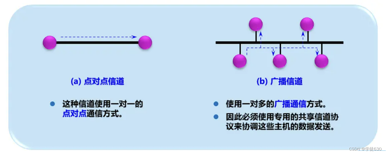
The data link layer is the lower layer of computer networks. There are two main types of channels used by the data link layer:
-
point-to-point channel
-
broadcast channel
LAN belongs to the data link layer
Although the LAN is a network. But we do not discuss LAN in the network layer. This is because what is discussed at the network layer is the interconnection of multiple networks, and how packets are forwarded from one network to another through a router.
In the same LAN, how can packets be transmitted from one host to another host without being forwarded by the router . From the perspective of the entire Internet, LAN still belongs to the scope of the data link layer.
Three important questions
The protocol data unit transmitted by the data link layer is a frame
framed
-
Encapsulation into framing (framing) is to add a header and a trailer before and after a piece of data, and then a frame is formed.
-
An important role of the header and trailer is to perform frame delimitation .
error control
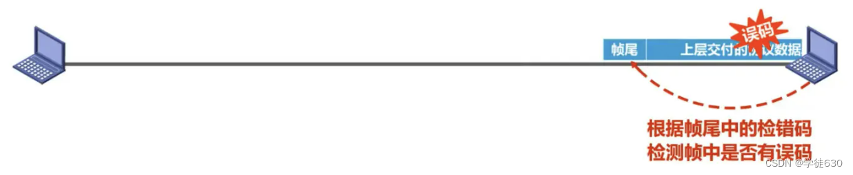
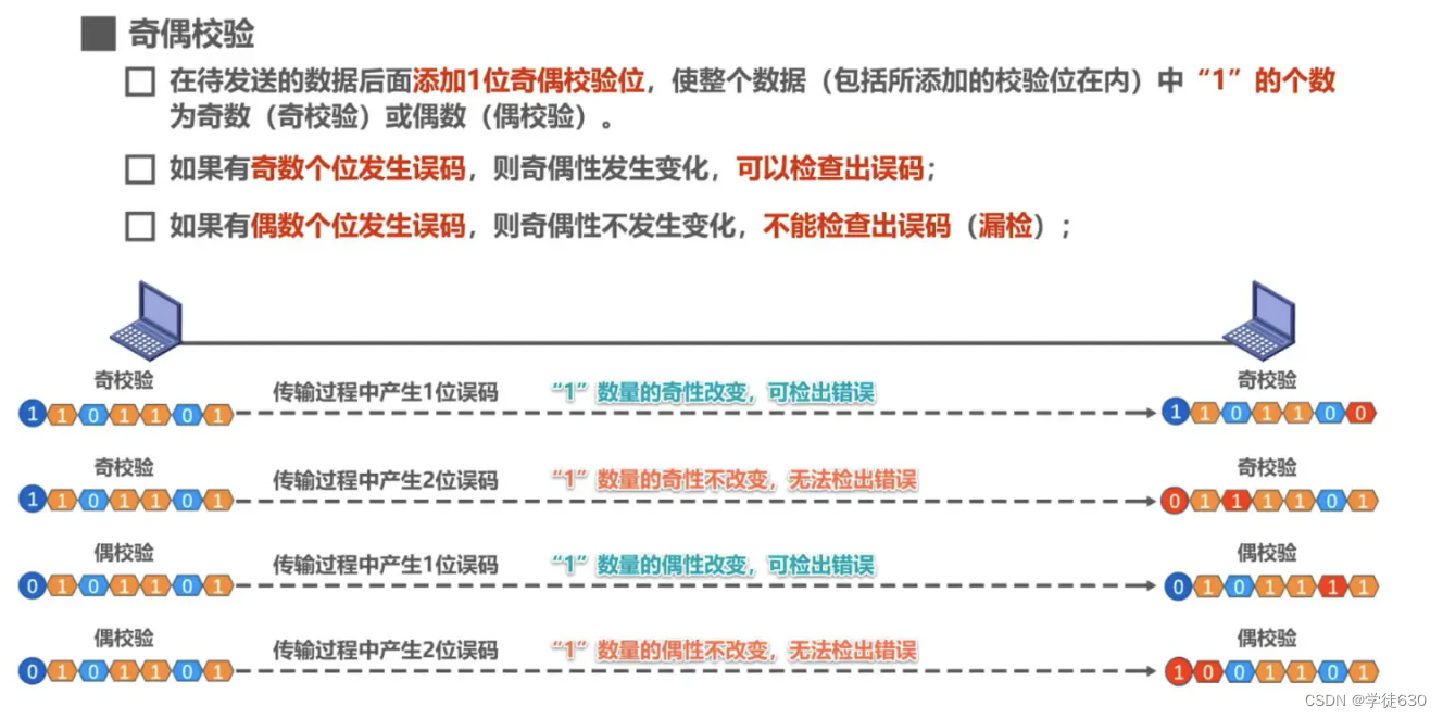
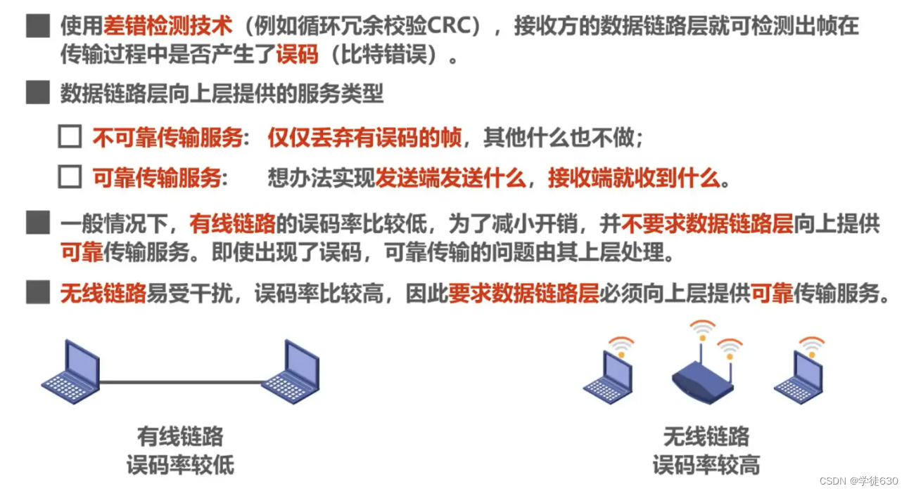
Bit errors may occur during transmission : a 1 may become a 0, and a 0 may become a 1.
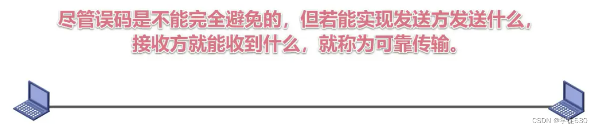
 Reliable transmission
After the receiving host receives a frame with errors, it will not accept the frame and will discard it.
If the data link layer provides unreliable services to its upper layers, then it is discarded and no more measures will be taken.
If the data link layer provides reliable services to the layers above it, additional measures are needed to ensure that the receiving host can re-receive a correct copy of the discarded frame.
The above three questions are all examples using the data link layer of point-to-point channels.
If the data link layer using the broadcast channel includes the above three problems, there are also some problems to be solved.
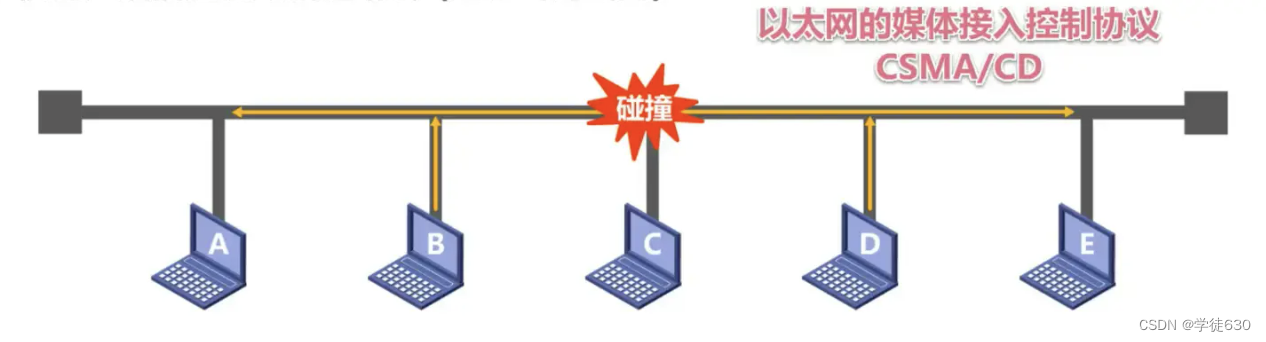
As shown in the figure, hosts A, B, C, D, and E are interconnected through a bus. Host A wants to send data to host C. The signal representing the frame will be transmitted to other hosts on the bus through the bus. Then the host How do B, D, and E know that the received frame is not sent to them, and how does host C know that the sent frame is sent to itself?

It can be solved using addressing (address)
Add the destination address of the frame to the frame and transmit it together
There is also the problem of data collision
With the development of technology and the maturity of switching technology,
Switched LANs using point-to-point links and link layer switches replaced shared LANs in the wired (LAN) world
Shared channel technology is still used in wireless LANs
3.2. Encapsulation into frames
introduce
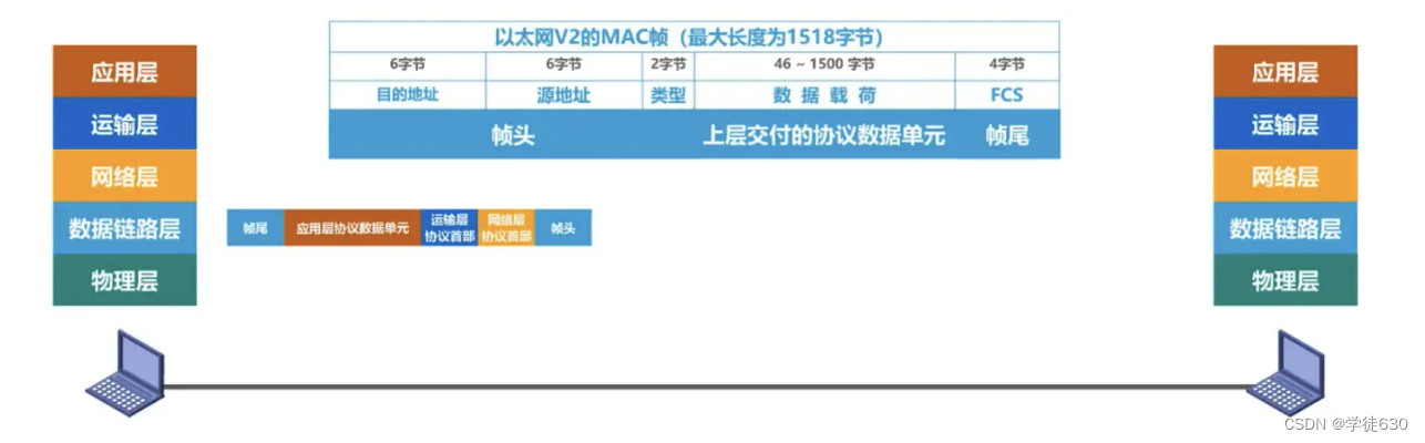
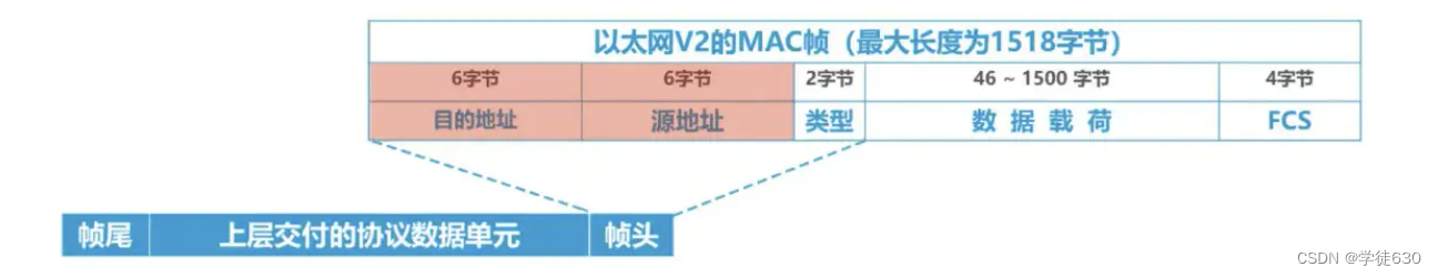
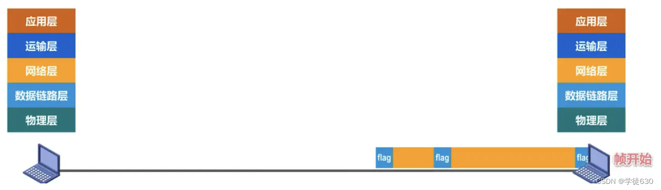
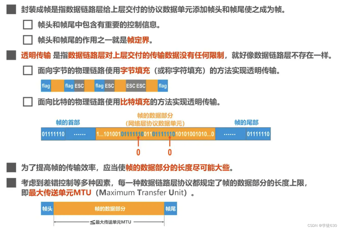
Encapsulation into frames means that the data link layer adds a frame header and a frame trailer to the protocol data unit delivered by the upper layer to make it a frame.
- The frame header and frame trailer contain important control information
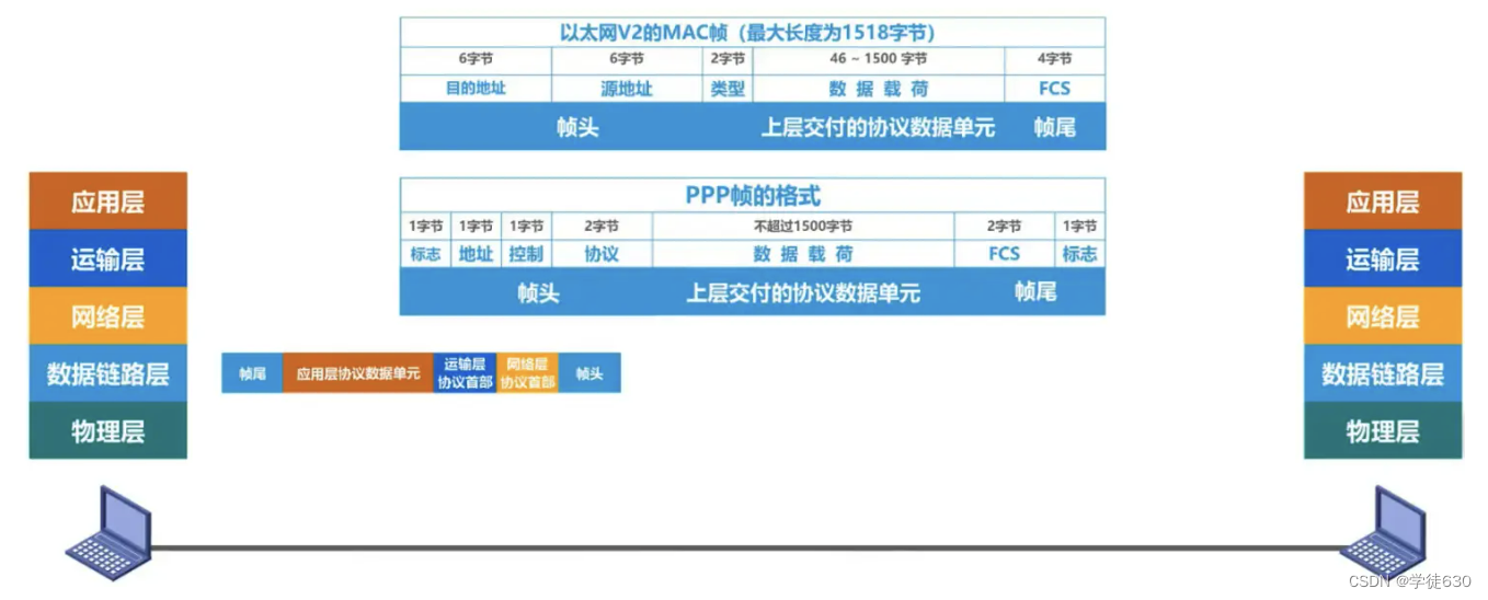
After the data link layer of the sender encapsulates the protocol data unit delivered by the upper layer into a frame, it also converts the bits constituting the frame into electrical signals through the physical layer and delivers them to the transmission media. Then the data link layer of the receiver How to extract individual frames from the bitstream delivered by the physical layer?
Answer: Frame header and frame trailer are needed for frame delimitation
But not every frame of the data link layer protocol contains a frame delimitation flag, such as the following example

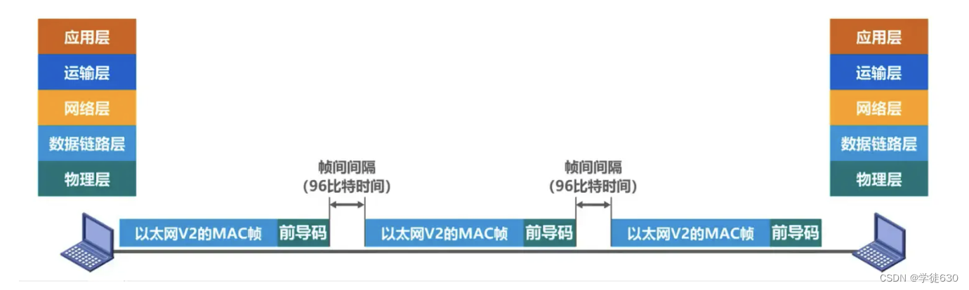
preamble
- Preamble: The function is to synchronize the receiver's clock
- Frame start delimiter: indicates that it is followed by a MAC frame
In addition, Ethernet also stipulates that the inter-frame interval is 96 bits. Therefore, MAC frames do not require end-of-frame delimiters (because they are not continuous)
Transparent transmission
Transparency means that something that actually exists looks as if it doesn't exist.
Transparent transmission means that the data link layer does not have any restrictions on the transmission data delivered by the upper layer , as if the data link layer does not exist
Transparent transmission does not interfere with or modify the transmitted data , and keeps the data transmitted as it is. At the data link layer, data is usually divided into data frames for transmission. Transparent transmission ensures that the contents of these data frames will not be modified or damaged during transmission, and the transmission method is transparent to the upper layer protocol, and the upper layer protocol does not need to know the details of the transmission.
The benefit of transparent transmission is to ensure the reliability and consistency of data, allowing different computers or network devices to communicate with each other without being affected by the underlying transmission details. This transmission method is very important in network communication, ensuring the effective transmission and correct processing of data.
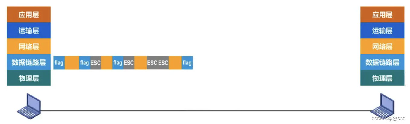
The frame definition flag is a specific data value. If the protocol data unit delivered by the upper layer happens to contain this specific value, the receiver cannot receive it correctly.
(Look at the picture below, because the frame delimitation mark is a specific data value. If there happens to be this value in the data, then when the receiver receives the intermediate data, it will judge that it is not data, but a delimiter, then it will It is unreasonable to give up receiving data from the rear)
Therefore, the data link layer should have restrictions on the data delivered by the upper layer, and its content cannot contain the value of the frame delimiter.
Solve the problem of transparent transmission
-
Solution : byte-oriented physical links use byte stuffing or character stuffing , and bit-oriented physical links use bit stuffing to achieve transparent transmission.
-
The data link layer at the sending end inserts an escape character "ESC" (its hexadecimal encoding is 1B) before the control character "SOH" or "EOT" appears in the data .
-
The data link layer on the receiving end removes the inserted escape characters before sending the data to the network layer.
-
If an escape character also appears in the data, an escape character ESC should be inserted before the escape character. When the receiving end receives two consecutive escape characters, the first one is deleted.
-
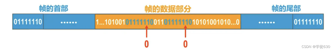
If it is a bit-oriented physical link, the method used is to insert a 0 after the fifth 1 in the 'frame delimiter' data that exists in the data to disassemble the frame delimiter data pattern. If the receiver receives When the data reaches five ones, the 0 characters written before transmission will be deleted. This can ensure the non-misjudgment of the frame delimiter and the consistency of the transmitted data.

The length of the data part of the frame
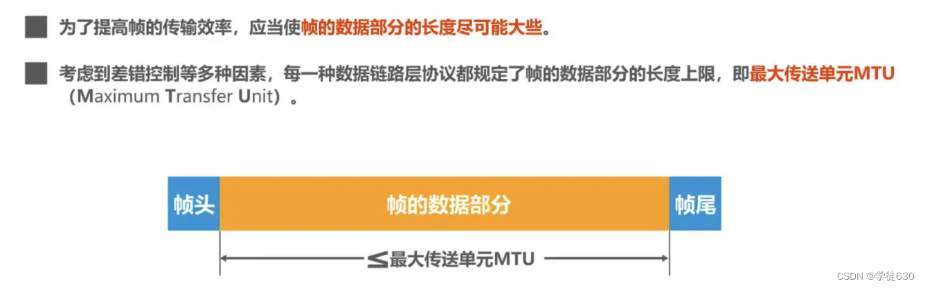
Summarize
3.3. Error detection
introduce

parity check
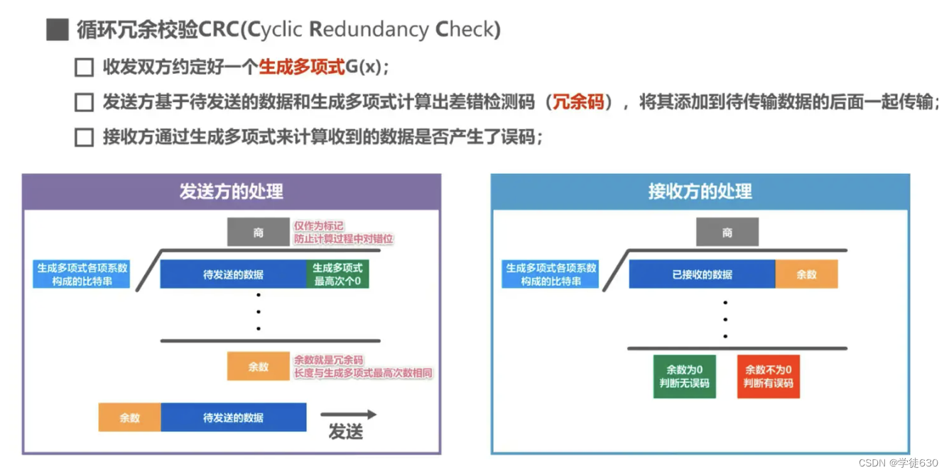
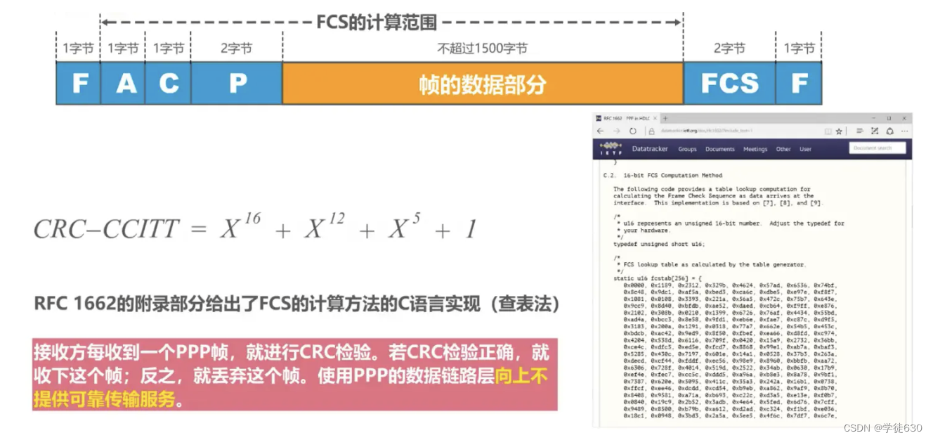
Cyclic Redundancy Check CRC (Cyclic Redundancy Check)

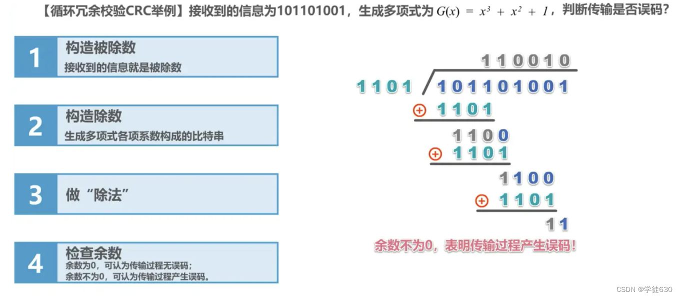
example

Summarize
Cyclic redundancy check CRC is an error detection method, while frame check sequence FCS is a redundant code added after the data
3.4. Reliable transmission
basic concept
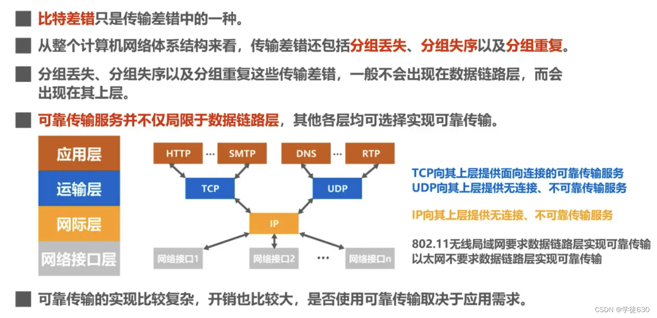
bit error
Other transmission errors

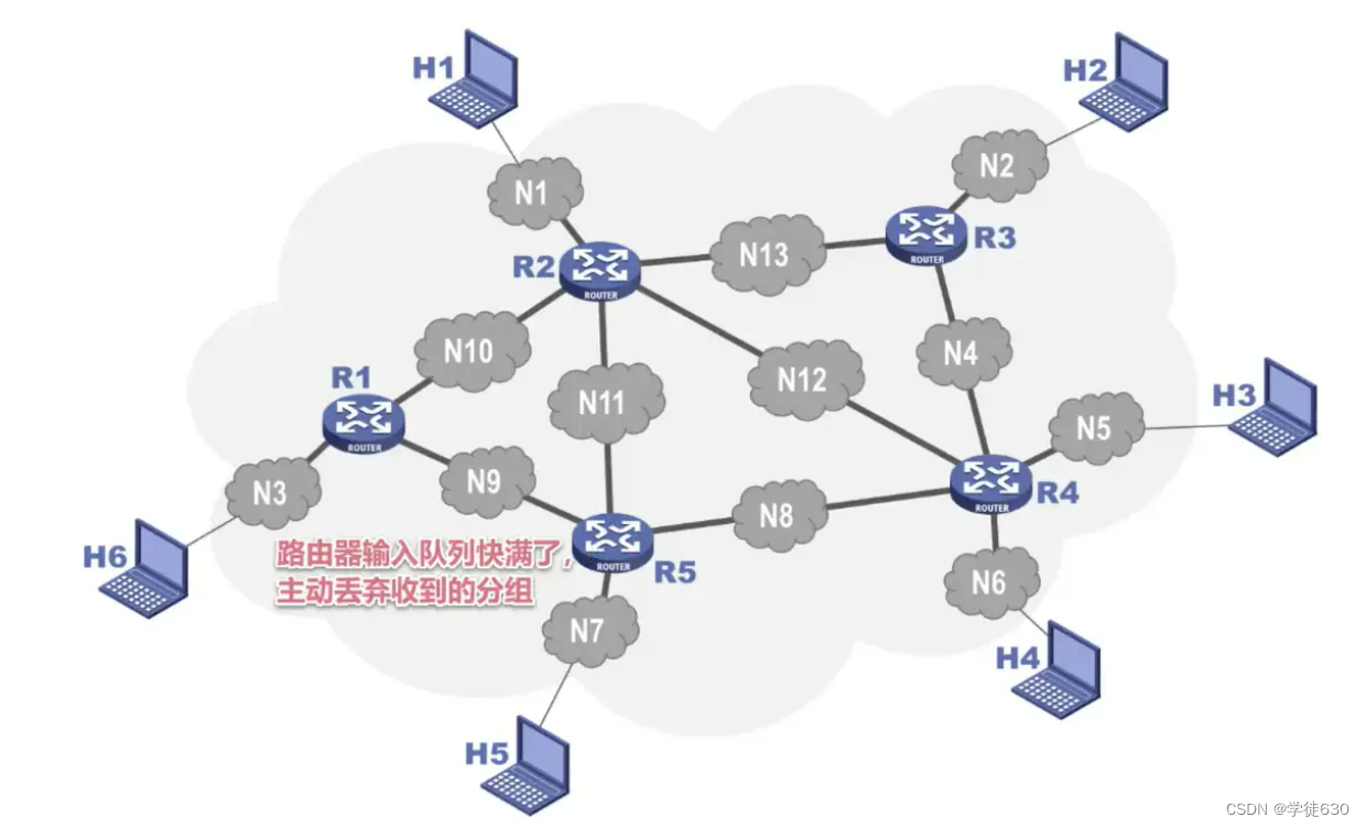
Packet lost
The router input queue is almost full and actively discards received packets.
packet out of order
The data does not arrive at the receiving end in the order it was sent.
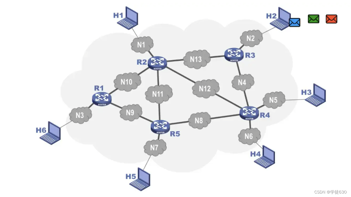
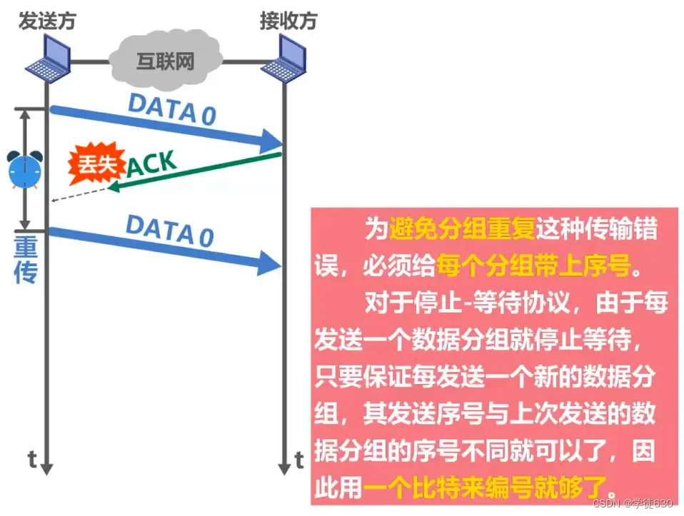
Repeat in groups
For some reasons, some packets are stuck in the network and do not arrive at the receiving end in time. This may cause the sending end to resend the packets. The retransmitted packets arrive at the receiving end, but after a period of time, the packets staying in the network will also reaches the receiving end, which causes packet duplication transmission errors.
Three reliable protocols
-
Stop-Wait Protocol SW
-
Fallback N frame protocol GBN
-
Select retransmission protocol SR
The basic principles of these three reliable transmission implementation mechanisms are not limited to the data link layer, but can be applied to protocols at all layers of the computer network architecture.
stop-wait protocol
Four Problems You May Encounter with Stop-Wait Protocols
Confirm and Deny
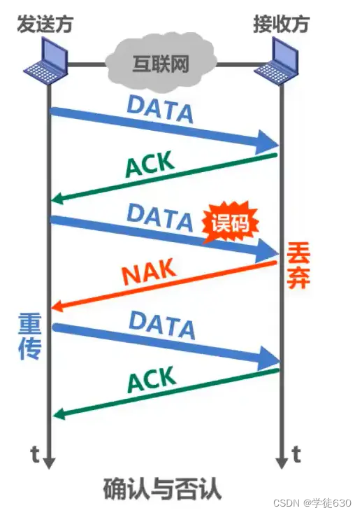
Timeout retransmission

confirmed lost

Since the data grouping needs to be numbered, does the confirmation grouping need to be numbered?
want. As shown below
confirmed late
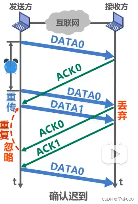
Note that the bottom data group in the picture is not the same data group as the previous data group with sequence number 0.
Precautions

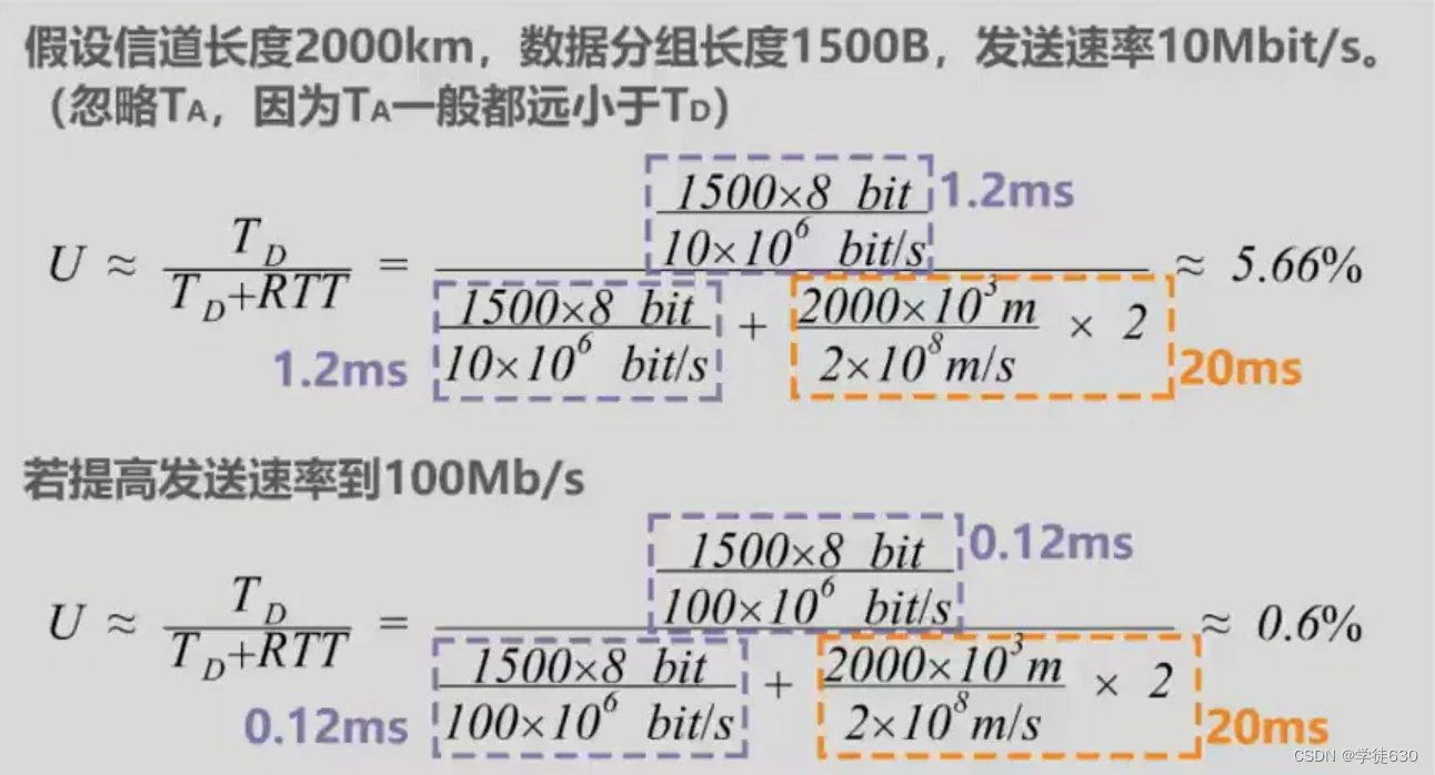
Stop-wait protocol channel utilization
Assume that there is a direct channel between the sender and receiver
-
TD : It is the sending delay consumed by the sender to send data packets.
-
RTT : is the round trip time between the sender and the receiver
-
TA : It is the sending delay spent by the receiver to send the confirmation packet.
TA is generally much smaller than TD and can be ignored. When RTT is much larger than TD, the channel utilization will be very low.


A reliable transmission protocol implemented through acknowledgment and retransmission mechanisms like the stop-and-wait protocol is often called the automatic request retransmission protocol ARQ ( A utomatic R epeat re Q uest), which means that the retransmission request is automatically performed because it is not required The receiver explicitly requests that the sender retransmit a sent packet.
Fallback N frame protocol GBN
Why use the fallback N frame protocol?
In the same period of time, the sender using the stop-wait protocol can only send one data packet, while the sender using pipeline transmission can send multiple data packets.
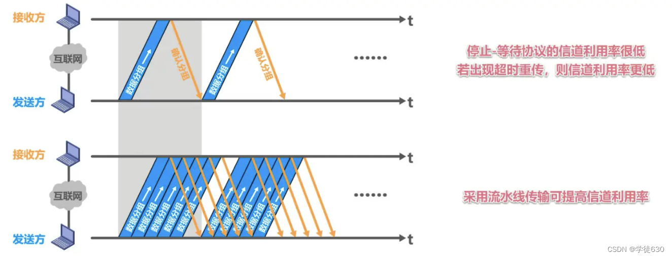
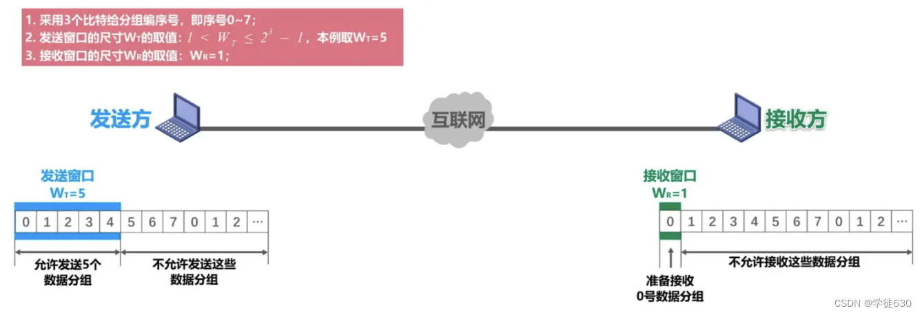
On the basis of pipeline transmission, the fallback N frame protocol uses the sending window to limit the number of data packets that the sender can send continuously.
error-free process
The sender groups data from 0 to 4 whose sequence numbers fall within the sending window and sends them out one after another.

They arrive at the receiver correctly through Internet transmission, that is, there is no disorder or error. The receiver receives them in order. Each time one is received, the receiving window slides forward by one position and sends an acknowledgment packet for the received packet to the sender. The transmission over the Internet correctly reaches the sender
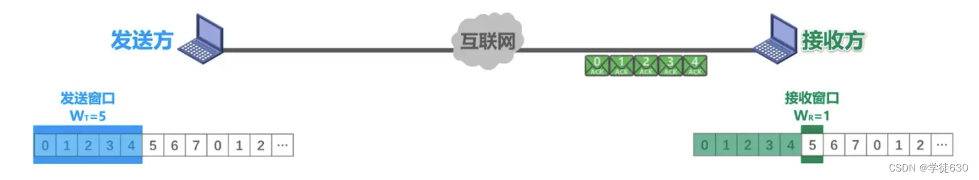
Every time the sender receives one, the sending window slides forward one position, so that a new sequence number falls into the sending window. The sender can delete the confirmed data packet from the cache, and the receiver can choose the opportunity to send the received data packet. The data packets are delivered to the upper layer for processing
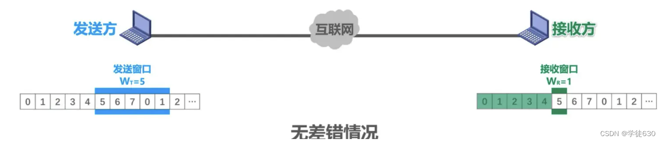
The sending end will continuously send multiple data frames, and these data frames are numbered in sequence. The receiving end will receive these data frames in the same order. After receiving a data frame, the receiving end will send an acknowledgment frame to the sending end. The acknowledgment frame carries the sequence number of the next data frame expected to be received.
Cumulative confirmation
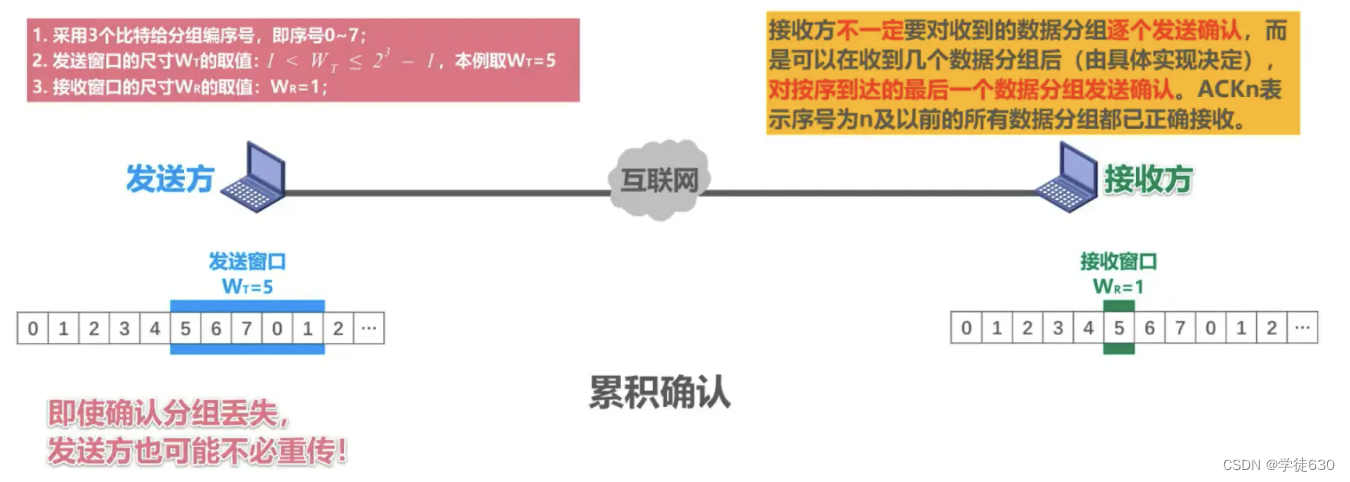
Cumulative acknowledgment means that the receiving end only sends acknowledgment frames that carry the sequence number of the next data frame it expects to receive , instead of sending an acknowledgment frame every time a data frame is received. When the sender receives the acknowledgment frame, it will know that all data frames before the acknowledgment frame have been correctly received and acknowledged by the receiving end.
Specifically, the sender will maintain a sliding window with a size of N. The sender will continuously send data frames within the window. Each time a data frame is sent, the sender will start a timer. If the sender receives the expected acknowledgment frame before the timer expires, it slides the sliding window forward one position and resets the timer. If the sender receives a timed-out acknowledgment frame or no acknowledgment frame is received, it will resend all data frames within the window. In this way, the sending end ensures reliable transmission of data.
Cumulative confirmation
advantage:
- Even if a packet is acknowledged as lost, the sender may not have to retransmit it
- Reduce receiver overhead
- Reduce usage of network resources
shortcoming:
- Unable to promptly reflect to the sender the data packet information that the receiver has correctly received
There is an error situation
When transmitting data packets, a bit error occurred in data packet No. 5, and the receiver discovered the error through the error detection code in the data packet.
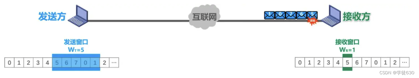
So the packet (the problematic packet) is discarded, and the remaining four packets that subsequently arrive do not match the sequence numbers of the receiving window.

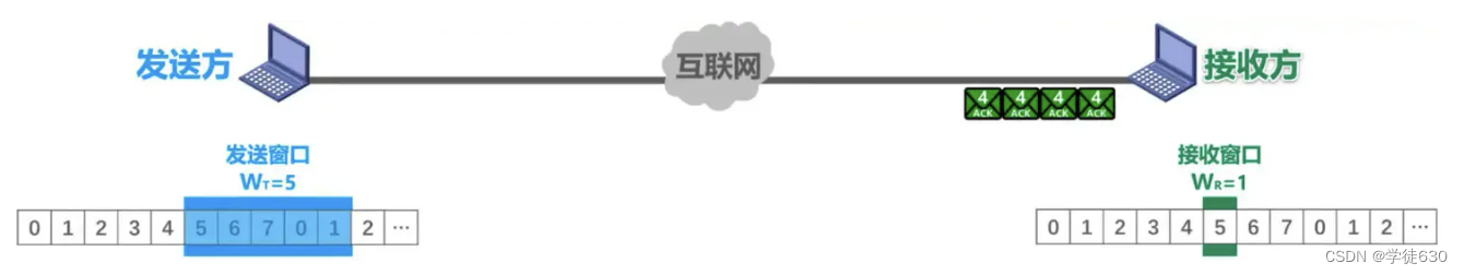
The receiver also cannot receive them, discards them, and acknowledges the last data packet previously received in sequence, sending an ACK4. Each time a data packet is discarded, an ACK4 is sent.
When a duplicate ACK4 is received, it is known that there is an error in the previously sent data packet, so the retransmission can be started immediately before the timeout timer expires. The specific number of duplicate confirmations will be retransmitted immediately, depending on the specific implementation.
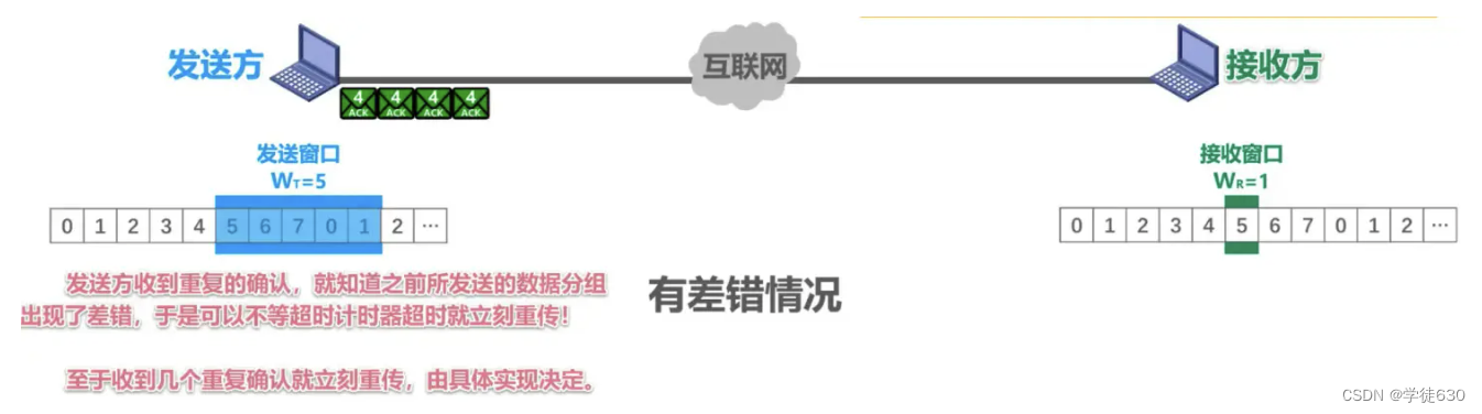
If these 4 duplicate confirmations are received, it will not trigger the sending to be retransmitted immediately, after a period of time. When the timeout timer expires, all data packets sent within the sending window will be retransmitted.

What happens if WT exceeds the value range, for example, WT=8?
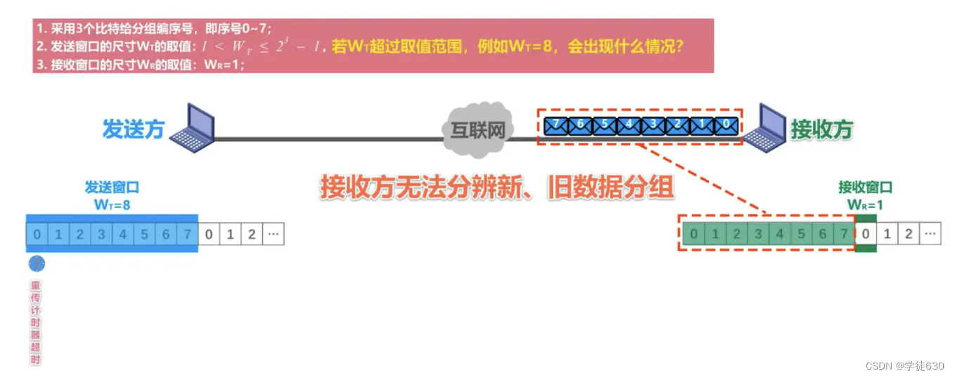

Summarize
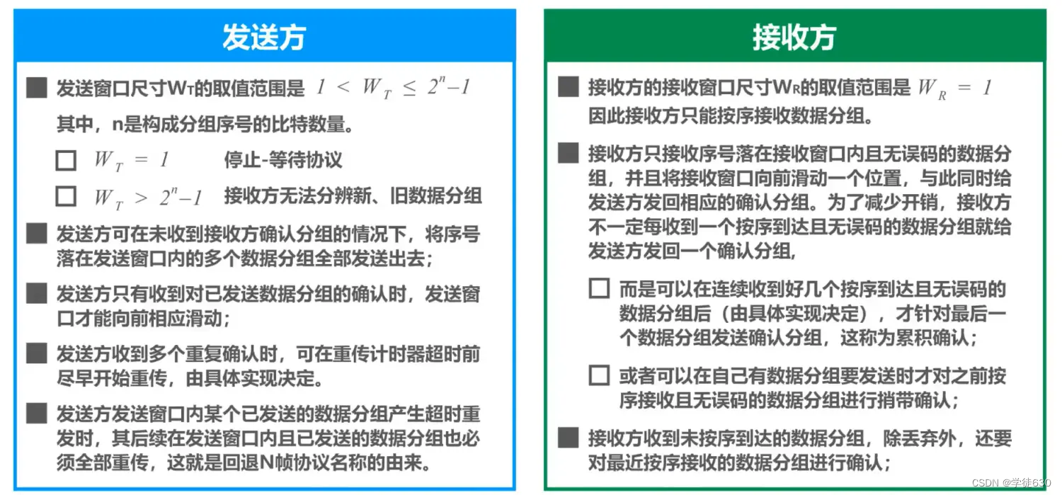
The fallback N frame protocol uses the transmission window to limit the number of data packets sent continuously by the sender on the basis of pipeline transmission. It is a continuous ARQ protocol.
During the working process of the protocol, the sending window and receiving window continue to slide forward, so this type of protocol is also called a sliding window protocol.
Due to the characteristics of the fallback N-frame protocol, when the communication line quality is poor, its channel utilization is not higher than that of the stop-and-wait protocol.
Select retransmission protocol SR
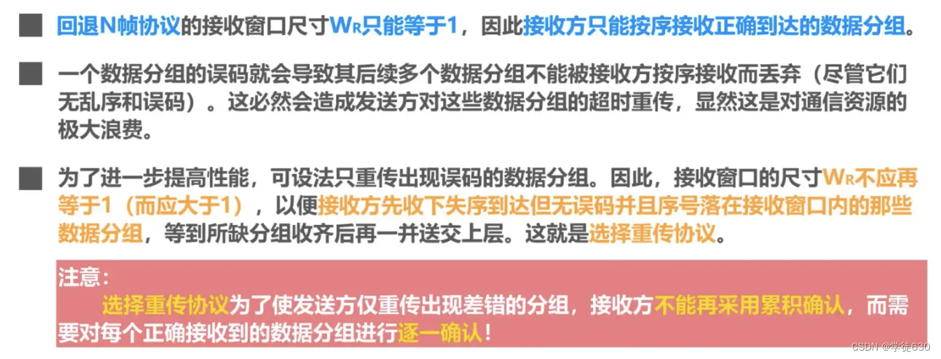
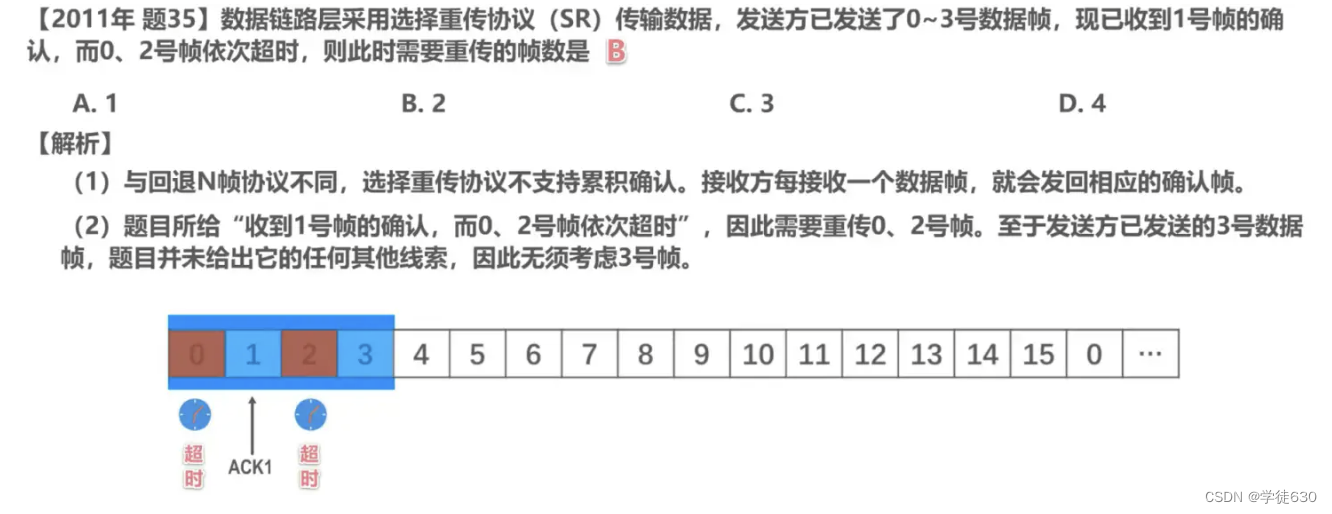
In the SR protocol, the sending end numbers and sends data frames in sequence , and the receiving end receives these data frames in the same order. Different from the GBN protocol, the receiving end will confirm each received data frame separately. Each time the receiving end receives a data frame, it will send an acknowledgment frame to the sending end. The acknowledgment frame carries the sequence number of the data frame .
Specifically, the sender maintains a sending window and a receiving window. Data frames within the sending window have been sent but no acknowledgment has been received , and data frames within the receiving window have been received but have not been processed by the upper-layer application . The sender will periodically send data frames that have not received confirmation within the window and start a timer.
When a data frame is received, the receiving end acknowledges the data frame and delivers it to the upper-layer application. If the receiving end finds a missing data frame, it will send a selective acknowledgment frame to the sending end, carrying the sequence number of the next data frame it expects to receive. After receiving the selective acknowledgment frame, the sender will only retransmit the data frames confirmed by the acknowledgment frame, rather than retransmitting all data frames within the window.
The receiving end will discard the received duplicate data frames and will not send an acknowledgment frame. After receiving the confirmation frame, the sender will delete the confirmed data frame from the sending window and slide the window to allow new data frames to be sent.
The selective retransmission protocol retransmits data frames in a selective manner and only retransmits lost data frames, thereby improving the efficiency of the protocol. It can reduce the retransmission burden on the sender and allow the receiver to process data frames in an out-of-order manner. However, compared with the GBN protocol, the SR protocol needs to maintain more states and logical judgments at both the sending end and the receiving end.
To sum up, the Selective Retransmission Protocol (SR) achieves the reliability of data transmission through a selective retransmission mechanism. The sender maintains the sending window and the receiving window, sends data frames in order, and performs selective retransmission or sliding operations based on the confirmation status of the receiving end. The receiving end acknowledges received data frames in a selective manner and handles out-of-order reception. In this way, the SR protocol can improve the efficiency and reliability of data transmission.

3.5. Point-to-Point Protocol PPP
-
Point-to-Point Protocol PPP (Point-to-Point Protocol) is currently the most widely used point-to-point data link layer protocol
-
The PPP protocol was developed by the Internet Engineering Task Force IEIF in 1992. After revisions in 1993 and 1994, the current PPP protocol has become the official standard of the Internet [RFC1661, RFC1662]
-
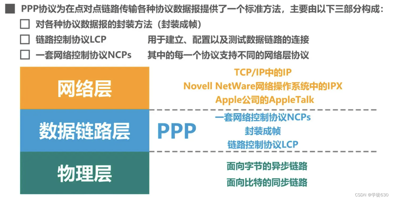
A protocol used by the data link layer. Its characteristics are: simple; it only detects errors instead of correcting them; it does not use sequence numbers and does not perform flow control; it can support multiple network layer protocols at the same time.
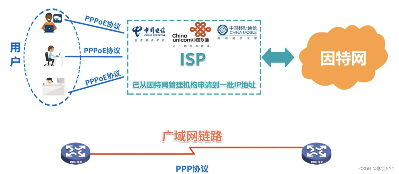
- PPPoE is a link layer protocol used by hosts with broadband Internet access
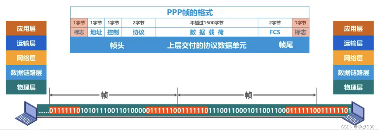
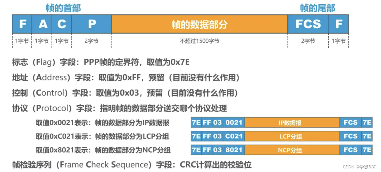
frame format
Special characters must be specified as frame delimiters
Transparent transmission
Transparency of data transmission must be ensured
Methods to achieve transparent transmission
- Byte-oriented asynchronous links: byte stuffing (inserting "escape characters")

- Bit-oriented synchronization link: bit stuffing method (insertion of "bit 0")

error detection
Ability to detect frames received at the receiving end and discard erroneous frames immediately .
working status
-
When a user dials into an ISP, the router's modem acknowledges the dial and establishes a physical connection.
-
The PC sends a series of LCP packets (encapsulated into multiple PPP frames) to the router.
-
These packets and their responses select some PPP parameters and perform network layer configuration. NCP gives the newly accessed PC
-
Assign a temporary IP address to make the PC a host on the Internet.
-
When the communication is completed, NCP releases the network layer connection and takes back the originally assigned IP address. Next, LCP releases the data link layer connection. The last thing released is the physical layer connection.

It can be seen that the PPP protocol is no longer a pure data link layer protocol, it also includes the content of the physical layer and network layer.
3.6. Media access control (media access control) - broadcast channel
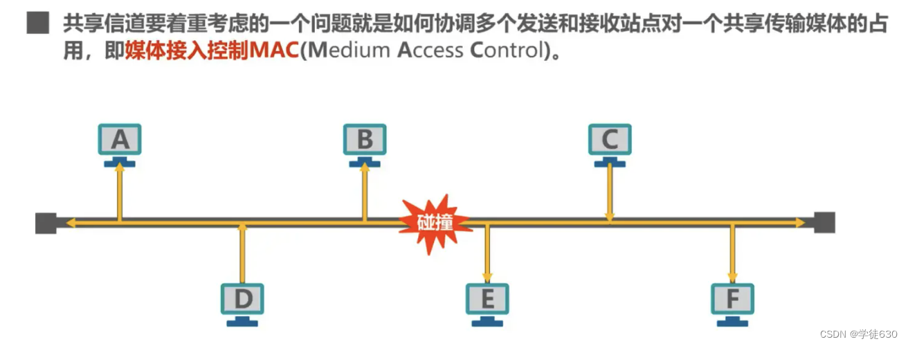
Media Access Control (Media Access Control) uses a one-to-many broadcast communication method
Medium Access Control is translated into media access control, and some are translated into media access control.
Data link layer of local area network
-
The main features of LAN are:
-
The network is owned by one unit;
-
Geographic scope and number of sites are limited.
-
-
LAN has the following main advantages :
-
With broadcast function, the entire network can be easily accessed from one site. Hosts on the LAN can share various hardware and software resources connected to the LAN.
-
To facilitate system expansion and gradual evolution, the location of each device can be flexibly adjusted and changed.
-
Improved system reliability, availability and survivability.
-

Two sublayers of the data link layer
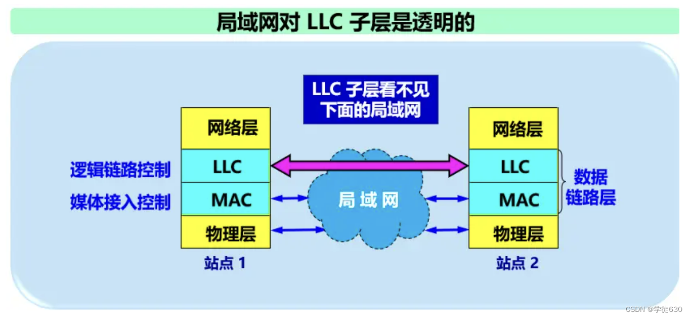
In order to make the data link layer better adapt to multiple LAN standards, the IEEE 802 committee split the data link layer of the LAN into two sub-layers :
-
Logical Link Control LLC (Logical Link Control) sublayer;
-
Media Access Control MAC (Medium Access Control) sublayer.
Contents related to access to the transmission media are placed in the MAC sublayer, while the LLC sublayer has nothing to do with the transmission media. Regardless of the LAN protocol used, it is transparent to the LLC sublayer.
basic concept
Why Media Access Control (Media Access Control)?
Problems caused by shared channels
If multiple devices send data on the shared channel at the same time, they will interfere with each other and cause the transmission to fail.
With the development of technology, the maturity of switching technology and the reduction of costs, switched LANs with higher performance using point-to-point links and link layer switches have completely replaced shared LANs in the wired field. However, due to the broadcast of wireless channels By nature, wireless LANs still use shared media technology
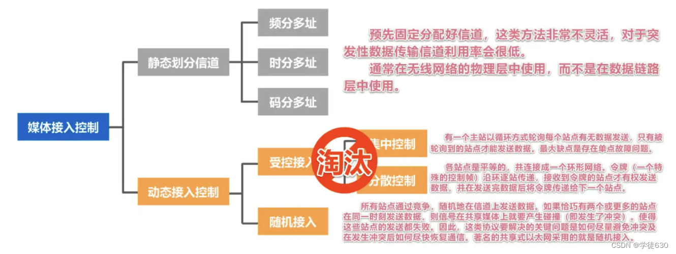
Static channel allocation
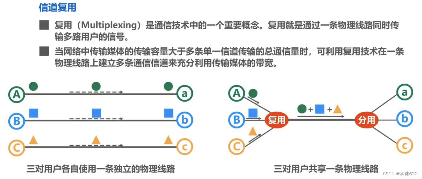
Channel multiplexing
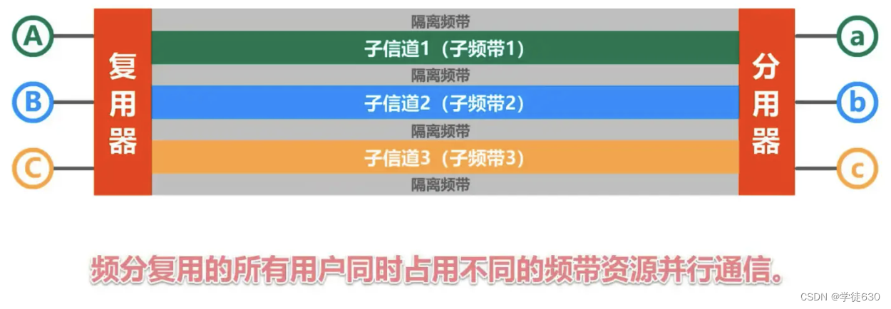
Frequency Division Multiplexing FDM (Frequency Division Multiplexing)
-
The entire bandwidth is divided into multiple parts. After the user is allocated a certain frequency band, he or she will occupy this frequency band throughout the communication process.
-
All users of frequency division multiplexing occupy different bandwidth resources at the same time (please note that the "bandwidth" here is the frequency bandwidth rather than the data transmission rate).
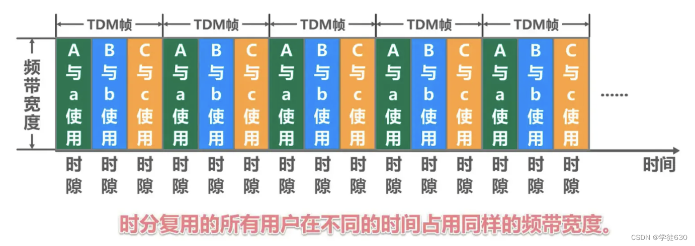
Time Division Multiplexing TDM (Time Division Multiplexing)
-
Time division multiplexing divides time into equal-length time division multiplexing frames (TDM frames) . Each time-division multiplexing user occupies a fixed number of time slots in each TDM frame, which is somewhat similar to the running principle of time slices distributed by the task scheduler in the Java language for threads.
-
The time slot occupied by each user appears periodically (the period is the length of the TDM frame).
-
TDM signals are also called isochronous signals.
-
All users of time division multiplexing occupy the same frequency bandwidth at different times.
Wavelength Division Multiplexing WDM (Wavelength Division Multiplexing)

Wavelength division multiplexing is frequency division multiplexing of light , using one optical fiber to transmit multiple optical carrier signals at the same time
The optical signal will attenuate after being transmitted for a certain distance, so an erbium-doped fiber amplifier is used to amplify the optical signal.
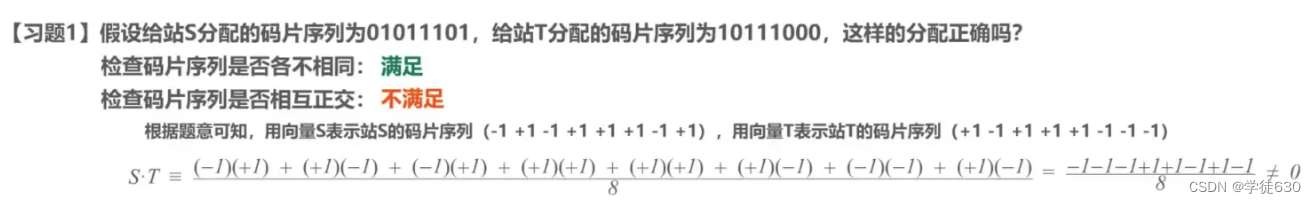
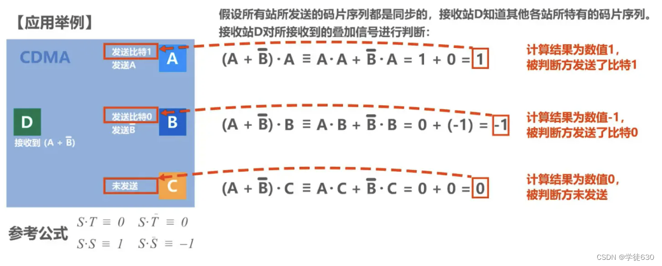
Code Division Multiplexing CDM (Code Division Multiplexing)


dynamic access control
Random access (CSMA/CD protocol)
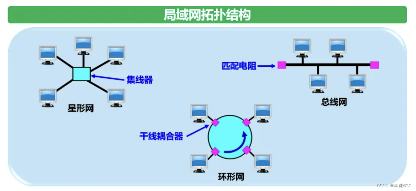
Bus LAN usage protocol: CSMA/CD
basic concept
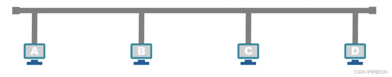
The original Ethernet connected many computers to a bus. Easy to implement broadcast communication. It was originally thought that this connection method was simple and reliable because there were no active devices on the bus.
Ethernet is a computer local area network technology . The IEEE 802.3 standard of the IEEE organization formulates the technical standard of Ethernet
Ethernet uses a connectionless working mode. The data frames sent are not numbered and do not require the other party to send back confirmation. When the destination station receives an error frame, it discards it and does nothing else.
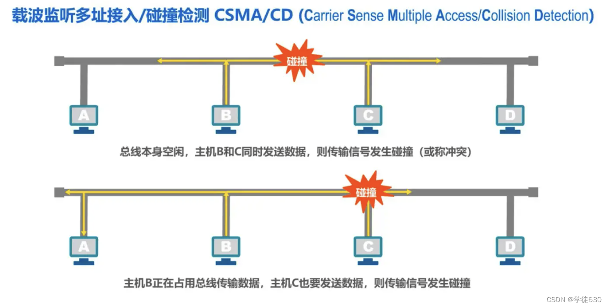
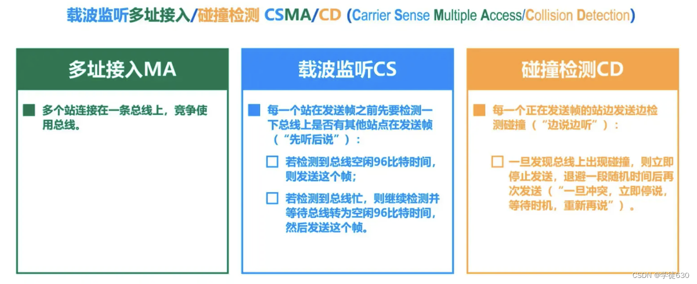
Multiple access MA
Indicates that many hosts are connected to a bus in a multi-point access manner.
Carrier sense CS
It means that before each station sends data, it must first detect whether there are other computers on the bus sending data. If so, it will not send data temporarily to avoid collisions.

There is no "carrier" on the bus. Therefore, "carrier monitoring" is the use of electronic technology to detect whether there are data signals sent by other computers on the bus.
Collision Detection CD
-
"Collision detection" means that the computer detects the signal voltage on the channel while sending data .
-
When several stations send data on the bus at the same time, the signal voltage swings on the bus will increase (add to each other).
-
When the signal voltage swing value detected by a station exceeds a certain threshold value, it is considered that at least two stations on the bus are sending data at the same time, indicating that a collision has occurred.
-
The so-called "collision" means that a conflict occurred. Therefore "collision detection" is also called "conflict detection".
-
When a collision occurs, the signal transmitted on the bus is severely distorted, and useful information cannot be recovered from it.
-
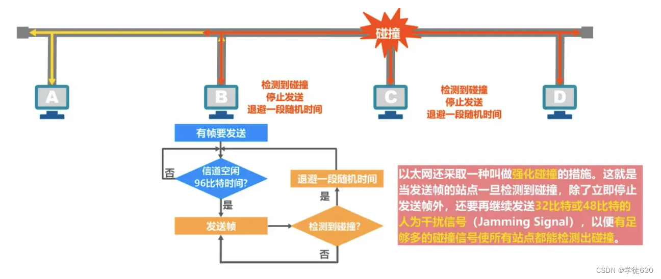
Each station that is sending data, once it discovers a collision on the bus, must immediately stop sending to avoid wasting network resources, and then wait for a random period of time before sending again.
Why do collision detection? Because signal propagation delay affects carrier monitoring

A needs 2 times the one-way propagation delay to detect a conflict with B's transmission.
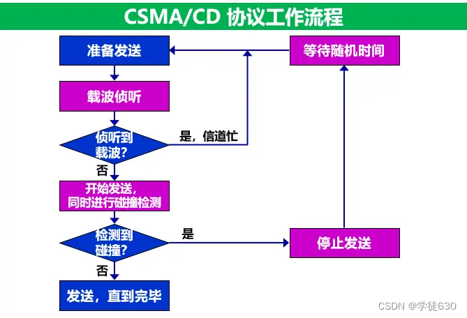
CSMA/CD protocol workflow
CSMA/CD protocol working - contention period (collision window)

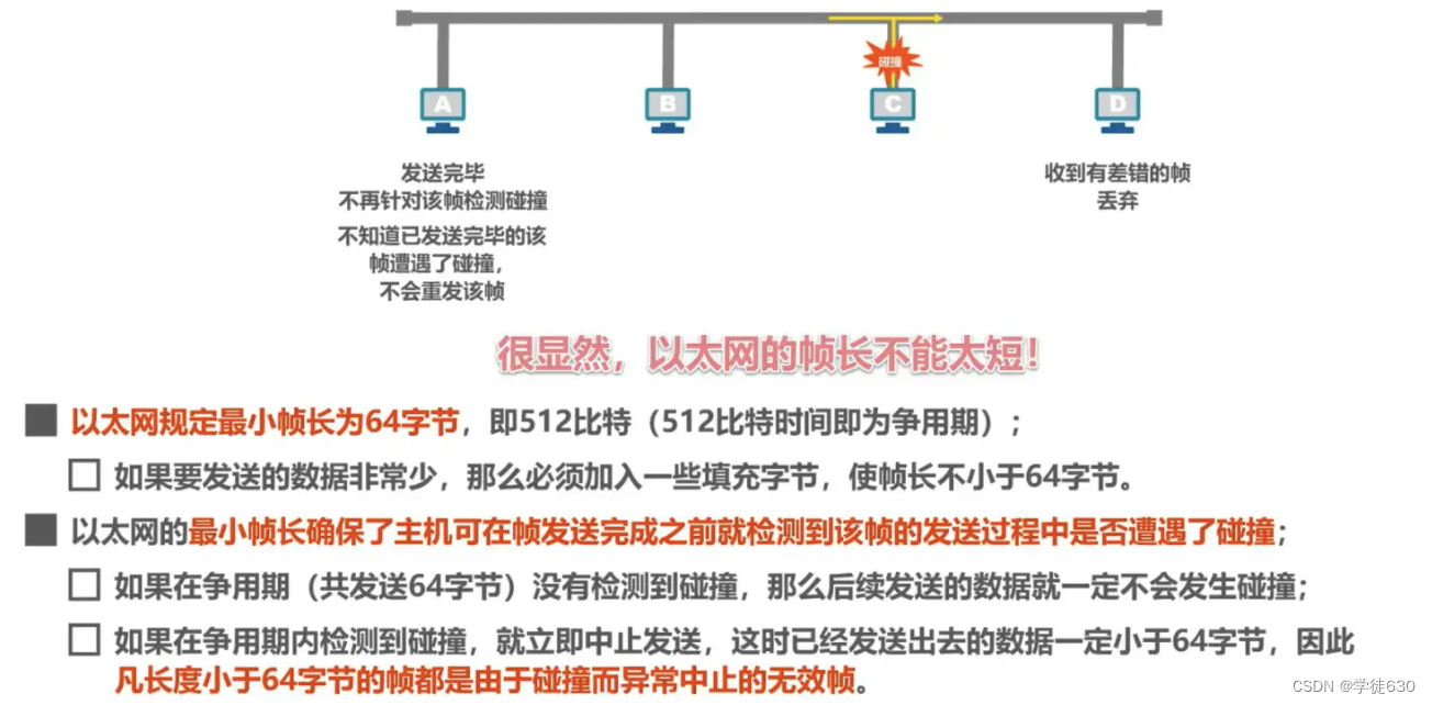
CSMA/CD protocol working - minimum frame length
CSMA/CD protocol working - maximum frame length
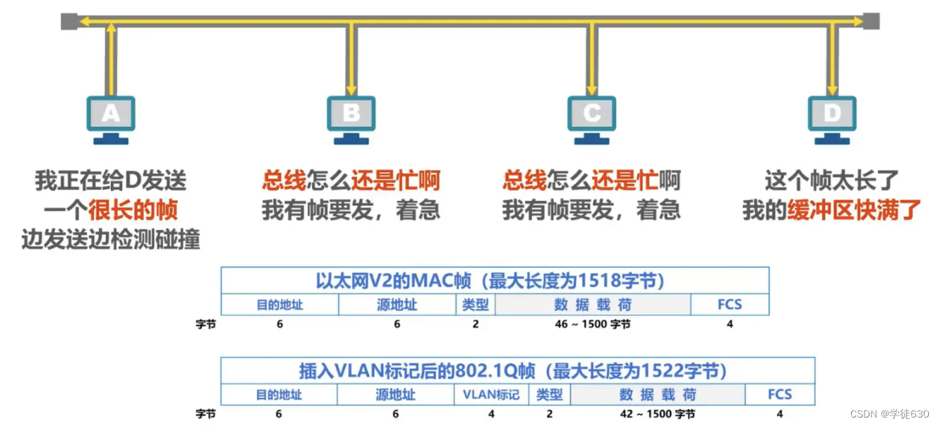
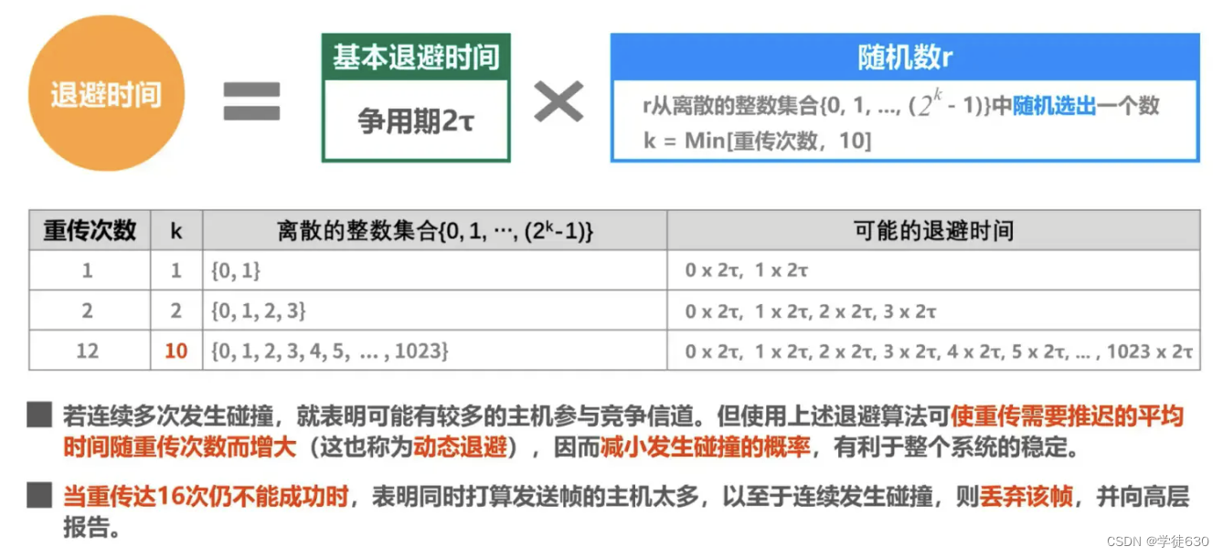
CSMA/CD protocol working - truncated binary exponential backoff algorithm
CSMA/CD Protocol Operation - Channel Utilization

CSMA/CD protocol work - frame reception process

Important features of the CSMA/CD protocol
-
Ethernet using the CSMA/CD protocol cannot perform full-duplex communication but can only perform bidirectional alternating communication (half-duplex communication).
-
Within a short period of time after each station sends data, there is the possibility of encountering a collision.
-
This uncertainty in transmission makes the average traffic volume of the entire Ethernet network much less than the maximum data rate of Ethernet.
The CSMA/CD protocol was used in early versions of various bus structures Ethernet and twisted pair Ethernet.
Today's Ethernet is based on switches and full-duplex connections, and there are no collisions, so there is no need to use the CSMA/CS protocol
Random access (CSMA/CA protocol)
Protocol used by wireless LAN: CSMA/CA
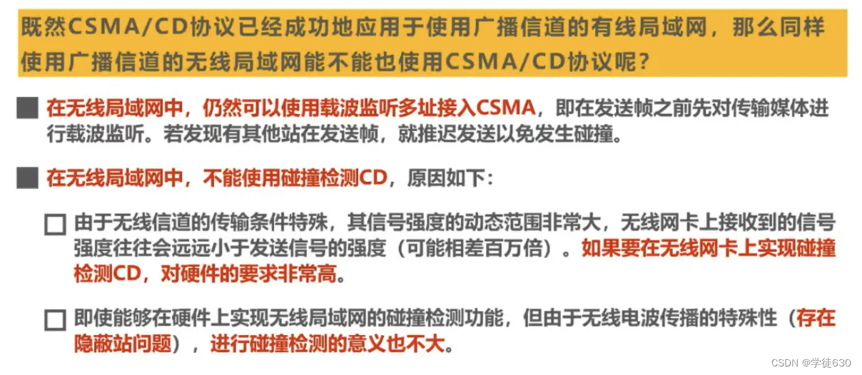
Why does wireless LAN use CSMA/CA protocol?


InterFrame Space IFS (InterFrame Space)

How the CSMA/CA protocol works
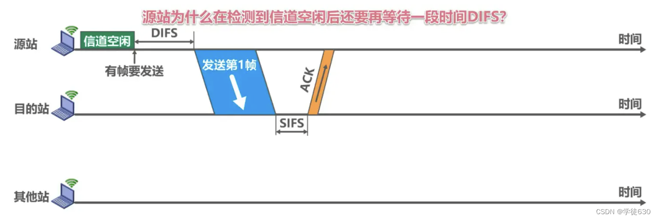
Why does the origin station wait for DIFS for a while after detecting that the channel is idle?
- Consider that there may be other stations with high priority frames to send. If so, high-priority frames must be sent first.
Why does the destination station have to wait for a period of SIFS before sending an ACK frame after correctly receiving the data frame?
- SIFS is the shortest interframe space that separates frames belonging to a conversation. During this time, a station should be able to switch from sending mode to receiving mode.

After the channel changes from busy to idle and the DIFS time passes, does it take a random backoff period before the channel can be used?
Prevent collisions caused by multiple sites sending data at the same time
When to use the backoff algorithm

Backoff algorithm of CSMA/CA protocol

Example of backoff algorithm
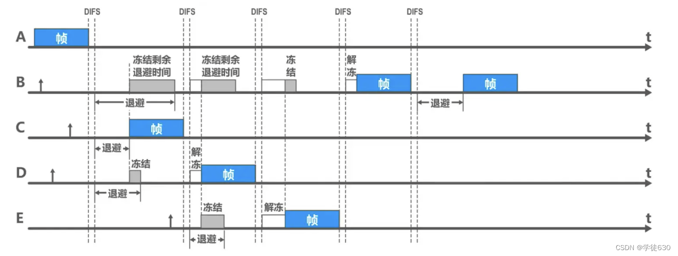
Channel reservation and virtual carrier monitoring of CSMA/CA protocol

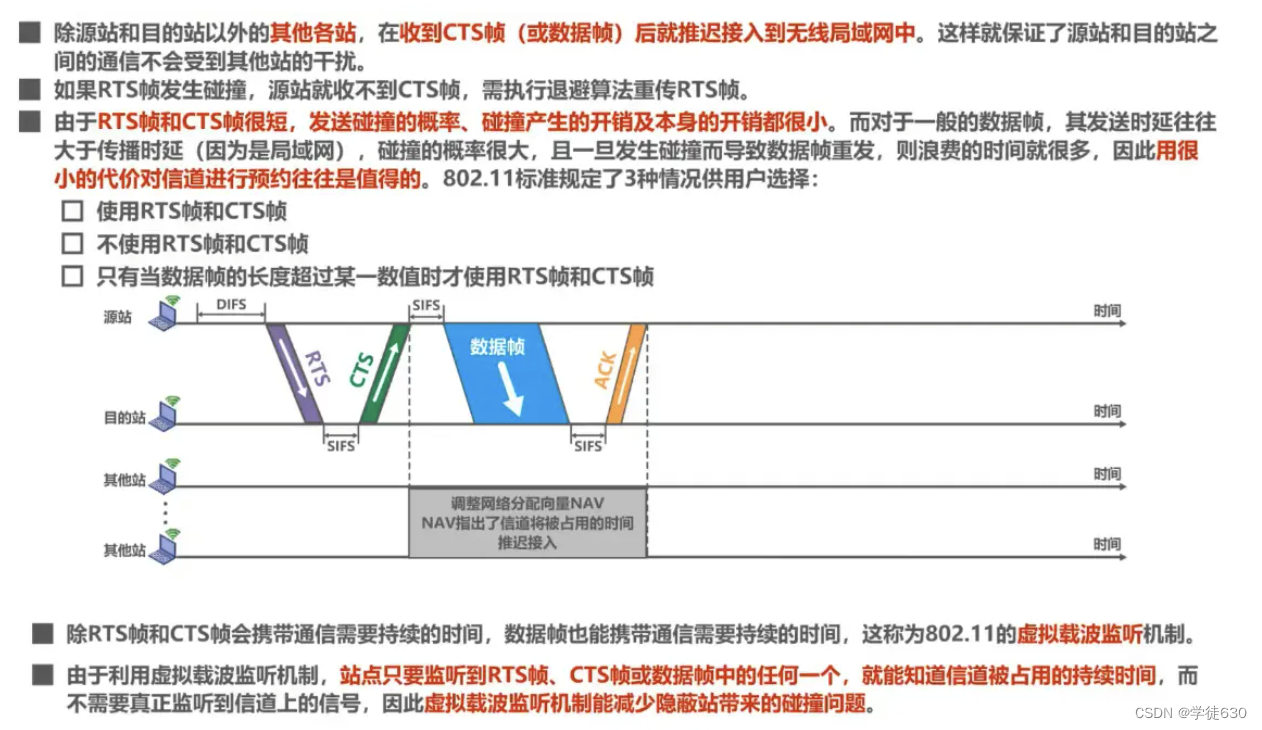
Example of how the virtual carrier sensing mechanism can reduce collision problems caused by hidden stations

3.7. MAC address, IP address and ARP protocol
MAC address
- The data link layer using point-to-point channels does not require the use of addresses
- Data link layers using broadcast channels must use addresses to distinguish hosts

The data link layer of the broadcast channel must use an address (MAC)
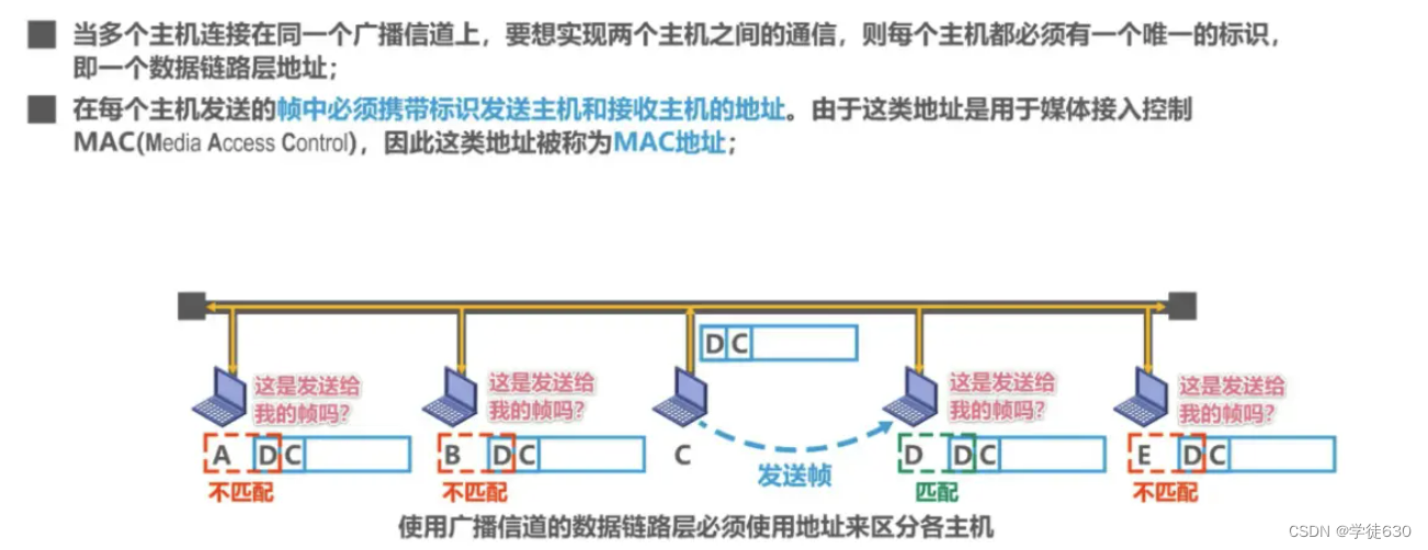
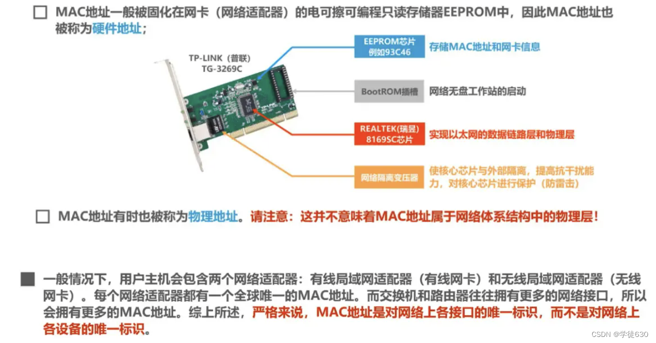
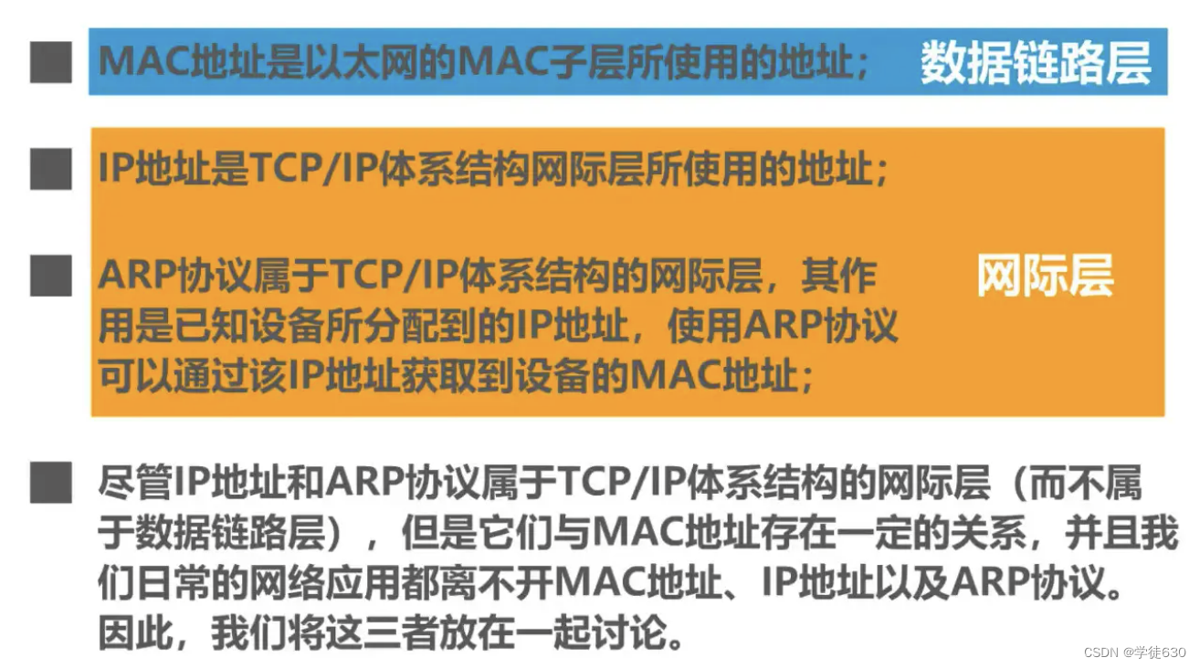
MAC address is also called hardware address or physical address . Please note: Do not be misled by the word "physical" into thinking that physical addresses belong to the physical layer and physical addresses belong to the data link layer.
MAC address format of IEEE 802 LAN
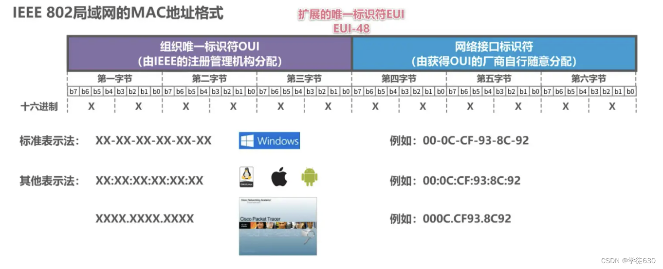
Organizational Unique Identifier OUI
- Manufacturers that produce network equipment need to apply for one or more OUIs from the IEEE registration authority
network interface identifier
- The manufacturer that obtains the OUI can allocate it at will.
EUI-48
- 48 is the number of digits in this MAC address
The IEEE has a target lifetime of 100 years (until 2080) for applications using the EUI-48 space, but adoption of EUI-64 is encouraged as an alternative
About invalid MAC frames
-
The length of the data field is inconsistent with the value of the length field;
-
The length of the frame is not an integer number of bytes;
-
Use the received frame check sequence FCS to detect errors;
-
The length of the data field is not between 46 ~ 1500 bytes.
-
The valid MAC frame length is between 64 ~ 1518 bytes.
Invalid MAC frames detected are simply discarded. Ethernet is not responsible for retransmitting dropped frames.
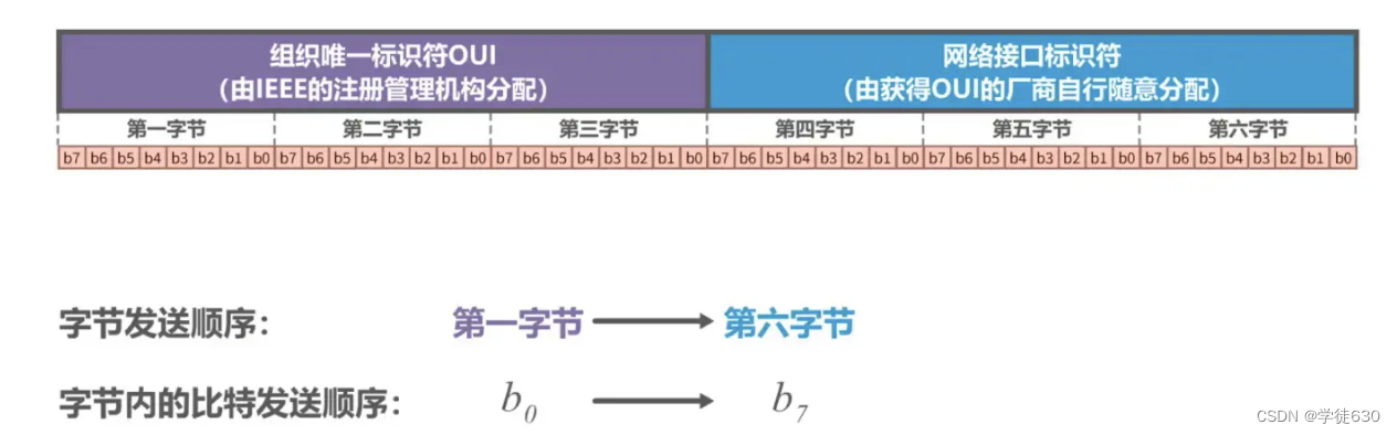
IEEE 802 LAN MAC address sending sequence
Unicast MAC address example

Host B sends a unicast frame to Host C. Host B must first construct the unicast frame , fill in the MAC address of host C in the destination address field in the frame header , fill in its own MAC address in the source address field, and add the frame The other fields in the header, the data payload and the frame trailer constitute the unicast frame.

Host B sends the unicast frame , and both hosts A and C receive the unicast frame.
Host A's network card finds that the destination MAC address of the unicast frame does not match its own MAC address, and discards the frame.
The network card of host C finds that the destination MAC address of the unicast frame matches its own MAC address and accepts the frame.
and hands the frame to its upper layer for processing
Broadcast MAC address example
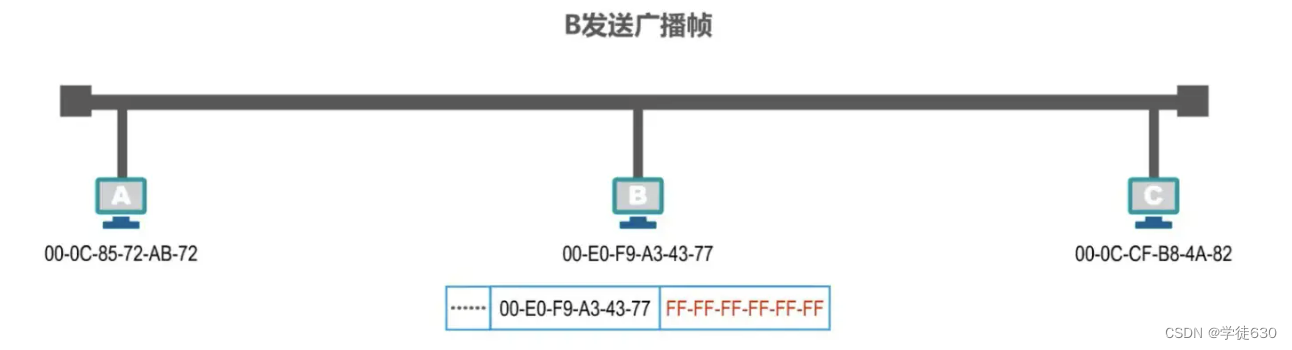
Assume that host B wants to send a broadcast frame . Host B must first construct the broadcast frame , fill in the broadcast address in the destination address field in the frame header , which is all F in hexadecimal, and fill in its own MAC address in the source address field. , plus other fields in the frame header, data load and frame tail, constitute the broadcast frame
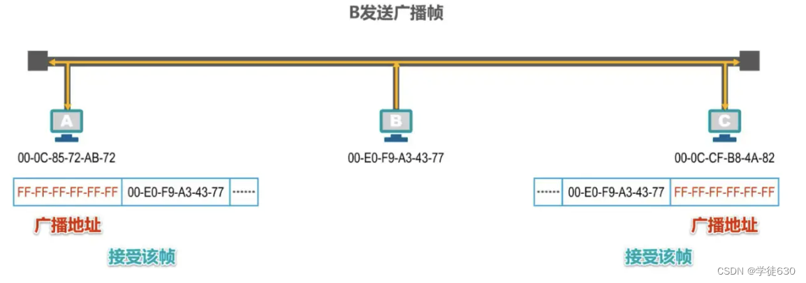
Host B sends the broadcast frame , and hosts A and C will receive the broadcast frame . If they find that the content of the destination address field in the header of the frame is the broadcast address , they know that the frame is a broadcast frame , and both hosts A and C accept it. The frame will be handed over to the upper layer for processing
Multicast MAC address example
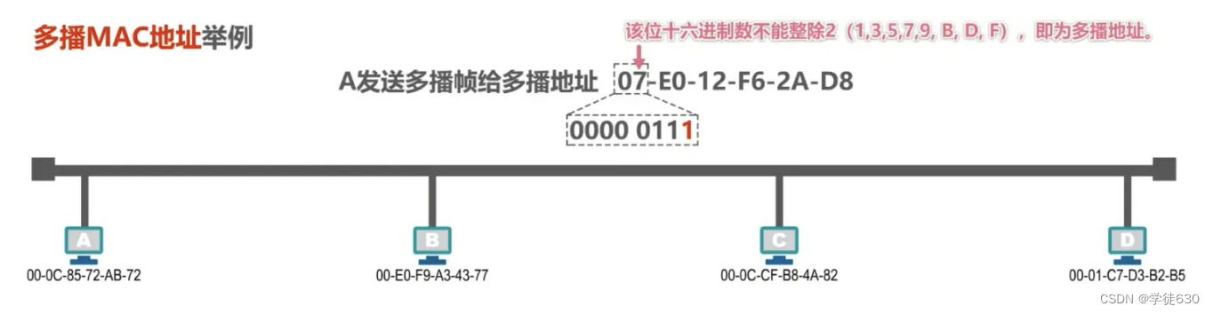
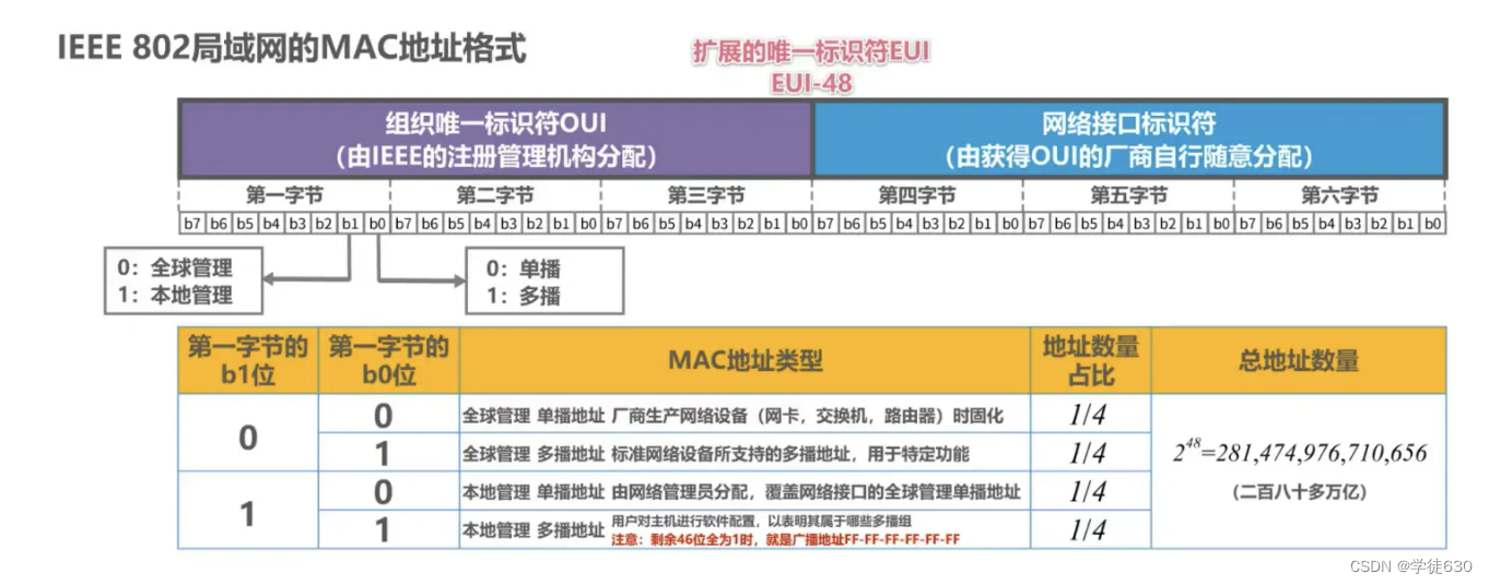
Assume that host A wants to send a multicast frame to this multicast address . The first byte from the left of the multicast address is written as 8 bits, and the lowest bit of the first byte is 1, which indicates that the address is a multicast address .
Quickly determine whether the address is a multicast address , that is, the hexadecimal number pointed by the arrow in the figure above cannot be divided by 2 (1,3,5,7,9,B,D,F), then the address is multicast. broadcast address
Assume that hosts B, C and D support multicast, and each user configures the multicast group list for their own hosts as follows:

Host B belongs to two multicast groups, host C also belongs to two multicast groups, and host D does not belong to any multicast group.

Host A must first construct the multicast frame , fill in the multicast address in the destination address field in the frame header , fill in its own MAC address in the source address, plus other fields in the frame header, data payload and frame trailer , which constitutes the multicast frame
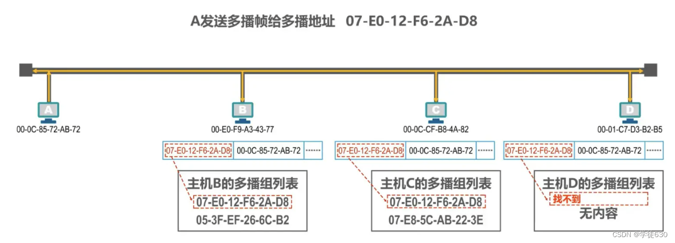
Host A sends the multicast frame , and hosts B, C, and D all receive the multicast frame.
Hosts B and C find that the destination MAC address of the multicast frame is in their own multicast group list , and both hosts B and C will accept the frame.
Host D finds that the destination MAC address of the multicast frame is not in its own multicast group list, and discards the multicast frame.
When configuring a multicast group list for a host for private applications, public standard multicast addresses must not be used.
IP address
IP addresses belong to the network layer and do not belong to the data link layer.
The following content talks about the use of IP addresses. Detailed IP address content is introduced in the network layer.
basic concept

Looking at IP address and MAC address from the perspective of network architecture
Changes in IP addresses and MAC addresses during data packet forwarding
The IP addresses and MAC addresses of each host and router interface in the figure are represented by simple identifiers
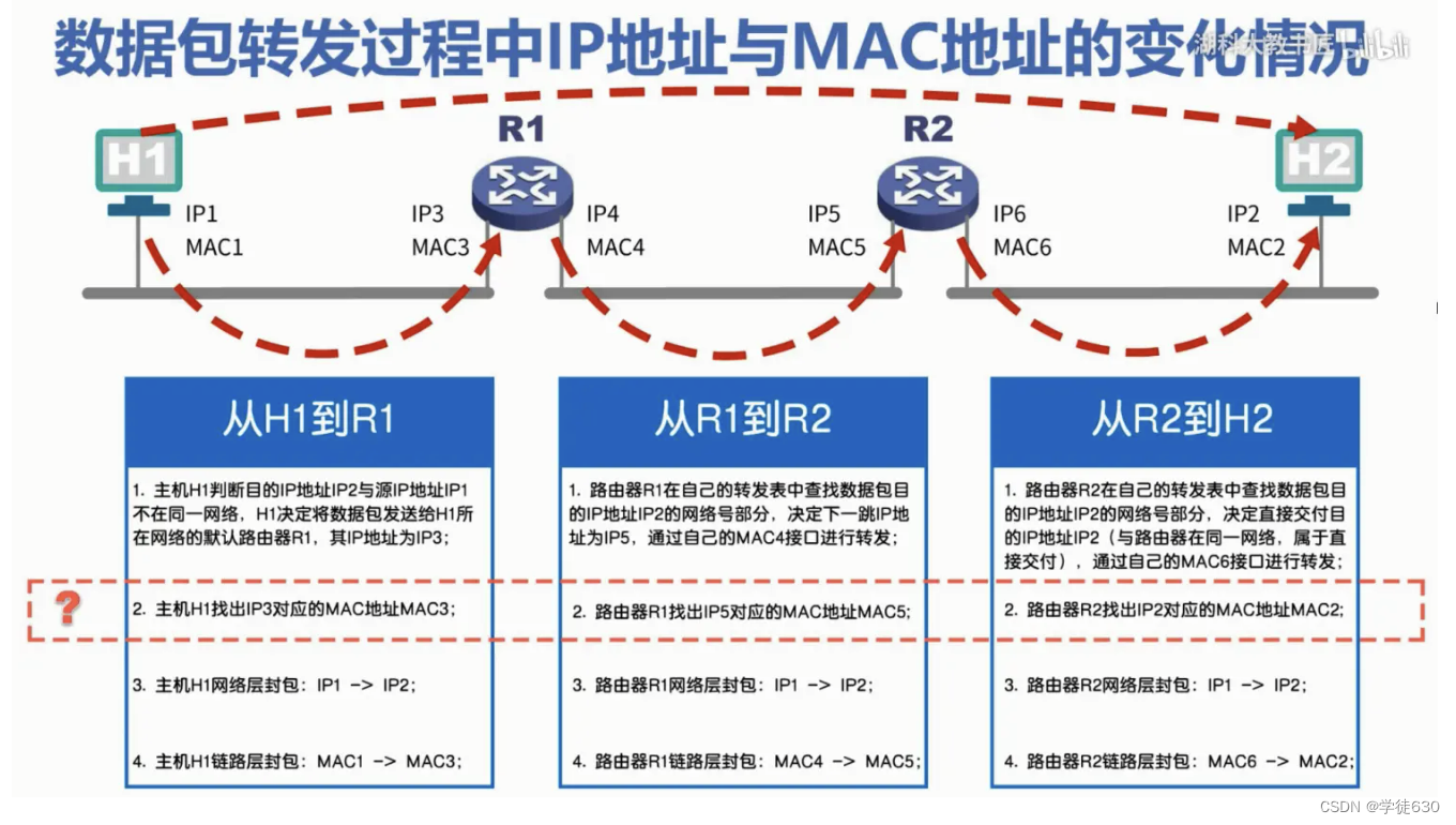
How to find out the corresponding MAC address from an IP address?
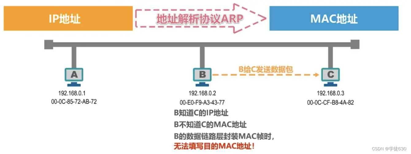
ARP protocol
ARP protocol
How to find out the corresponding MAC address from an IP address?
ARP (Address Resolution Protocol)
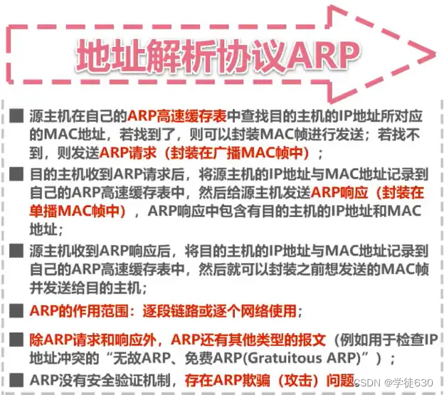
process
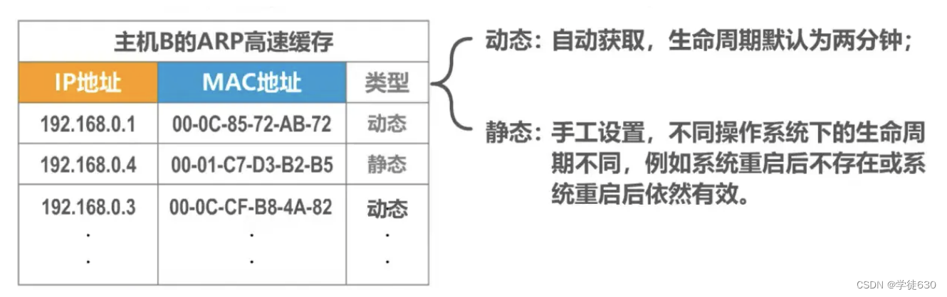
ARP cache table

When host B wants to send a data packet to host C, it will first search for the MAC address corresponding to the IP address of host C in its own ARP cache table, but cannot find it. Therefore, host B needs to send an ARP request message to Get the MAC address of host C

ARP request messages have specific formats. The above figure is just a brief description.
The ARP request message is encapsulated in a MAC frame and sent, and the destination address is the broadcast address.
Host B sends a broadcast frame encapsulated with an ARP request message, and other hosts on the bus can receive the broadcast frame.
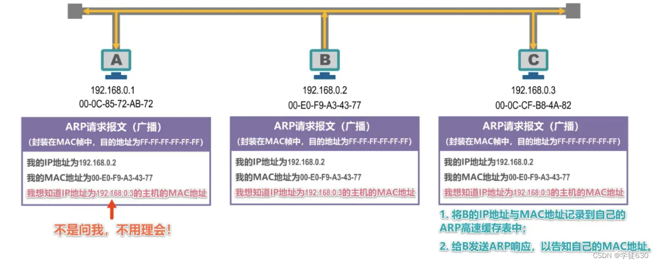
Host A and Host C that receive the ARP request message will hand the ARP request message to the upper-layer ARP process.
Host A finds that the IP address asked is not its own IP address, so it ignores it.
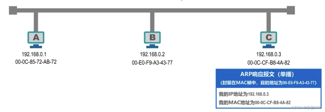
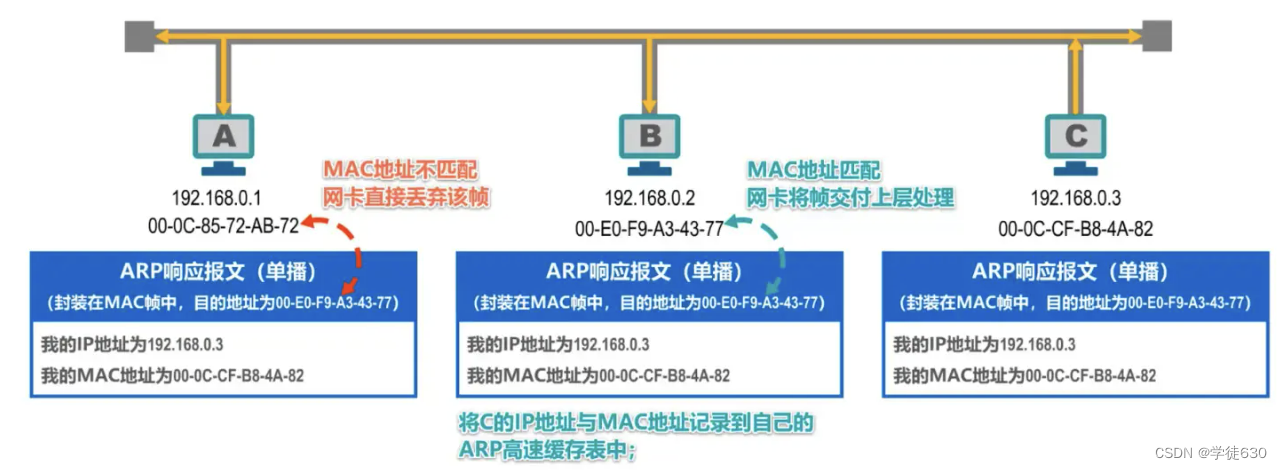
Host C discovers that the IP address it is asking for is its own IP address and needs to be processed accordingly.
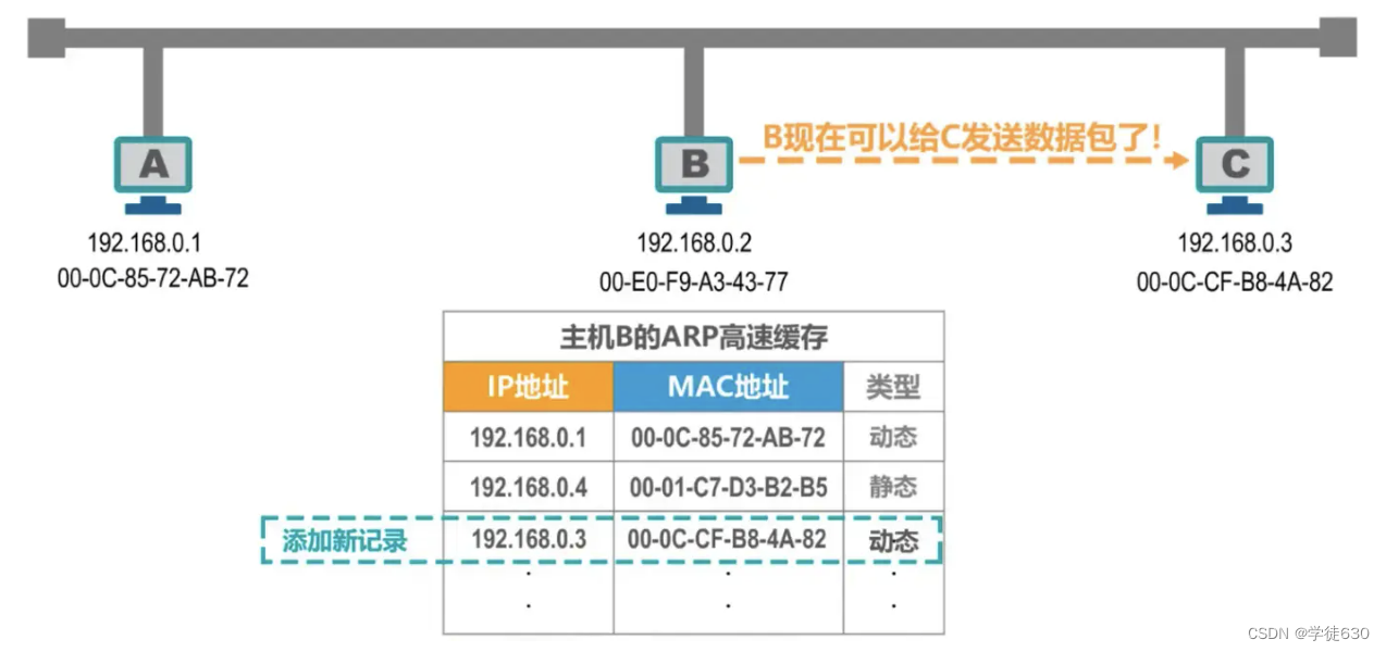
The difference between dynamic and static
The ARP protocol can only be used on a link or a network and cannot be used across networks.

The use of ARP protocol is performed on a link-by-link basis.
Summarize
The correspondence between IP address and MAC address in the ARP table will be automatically deleted regularly because the correspondence between IP address and MAC address is not permanent.
3.8. The difference between hub and switch
Hub - extends Ethernet at the physical layer
concept
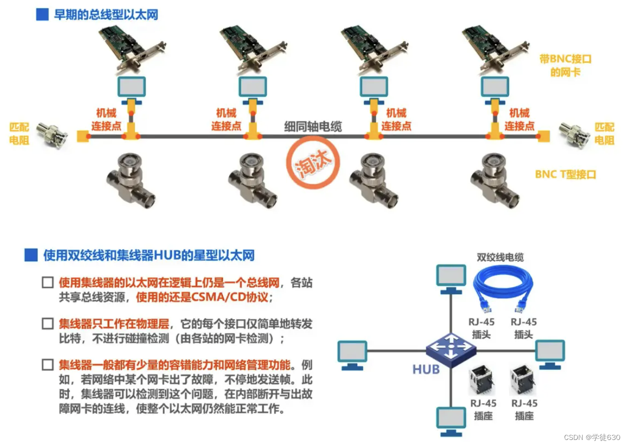
- Traditional Ethernet originally used thick coaxial cables, then evolved to use cheaper thin coaxial cables, and finally developed to use cheaper and more flexible twisted pairs.
- Ethernet using twisted pairs adopts a star topology, and a very reliable device called a hub is added to the center of the star .
- A hub can also be seen as a multi-port repeater. Each port can become a repeater. A repeater is a device that amplifies and transmits weakened signals.
- The Ethernet of the hub is still a bus network logically. It needs to use the CSMA/CD protocol to coordinate the competition between hosts for the bus. It can only work in half-duplex mode and cannot send and receive frames at the same time.
Hub HUB extends Ethernet at the physical layer
Use hub expansion : connect multiple Ethernet segments into a larger, multi-level star-structured Ethernet network

- advantage
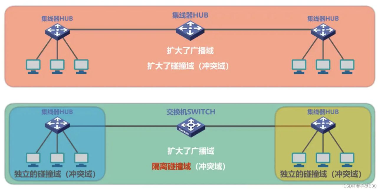
1.  使原来属于不同碰撞域的以太网上的计算机能够进行跨碰撞域的通信。


2.  扩大了以太网覆盖的地理范围。
- shortcoming
1.  碰撞域增大了,但总的吞吐量并未提高。


2.  如果不同的碰撞域使用不同的数据率,那么就不能用集线器将它们互连起来。
collision domain
-
Collision domain, also known as collision domain , refers to that part of the network where frames sent by one station will collide or conflict with frames sent by other stations.
-
The larger the collision domain, the higher the probability of collision.
Ethernet switches - extending Ethernet at the data link layer
concept
-
The more common method of extending Ethernet is at the data link layer.
-
In the early days, bridges were used , and now Ethernet switches are used .

bridge
- Bridges work at the data link layer.
- It forwards and filters received frames based on the destination address of the MAC frame.
- When the bridge receives a frame, it does not forward the frame to all interfaces, but first checks the destination MAC address of the frame, and then determines which interface to forward the frame to, or discards it.
switch
- The switching hub, introduced in 1990, can significantly improve the performance of Ethernet.
- Switching hubs are often called Ethernet switches (switches) or Layer 2 switches (L2 switches), emphasizing that such switches work at the data link layer.
- An Ethernet switch is essentially a multi-interface bridge
The difference between hub HUB and switch SWITCH

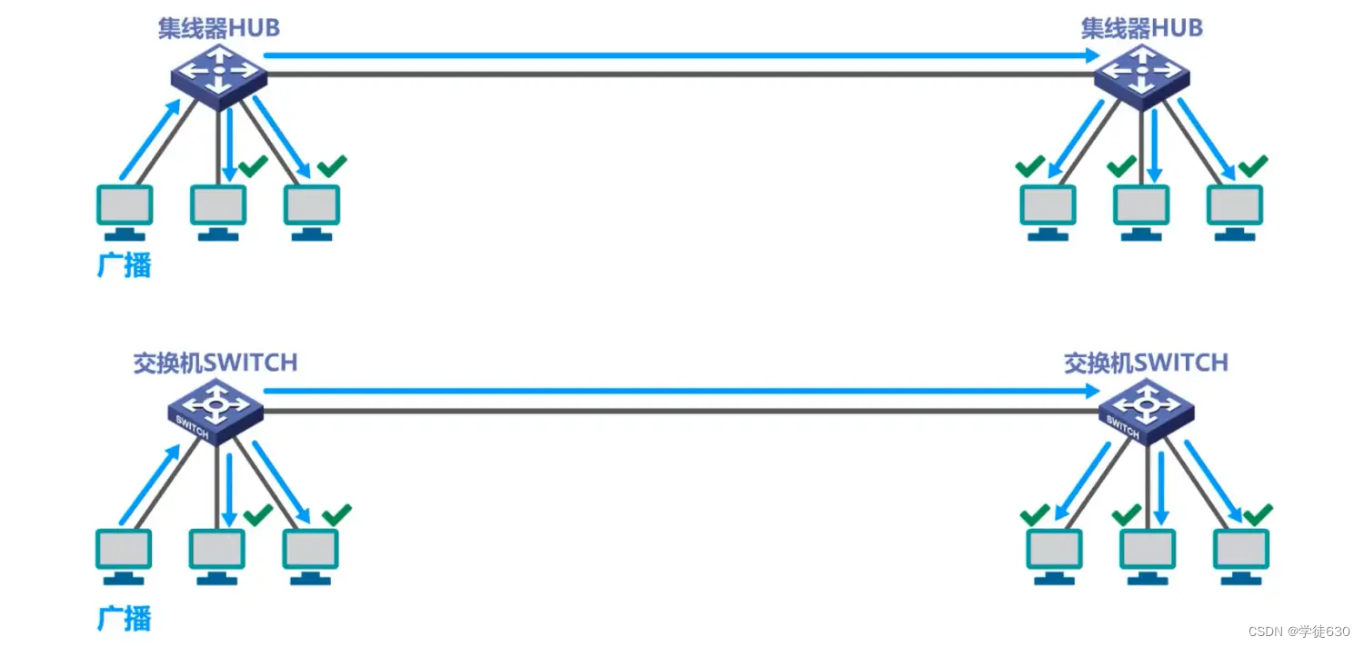
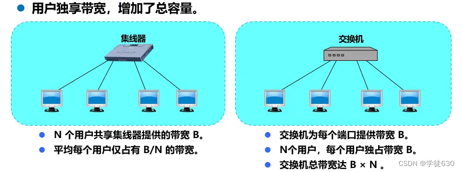
A host on a shared bus Ethernet network interconnected by a hub wants to send a unicast frame to another host. The unicast frame will be transmitted to each other host on the bus through the shared bus .
A host on a switched Ethernet network interconnected by switches wants to send a unicast frame to another host. After the unicast frame enters the switch, the switch will forward the unicast frame to the destination host instead of the network . Various other hosts of
The prerequisite for this example is to ignore the ARP process and assume that the frame exchange table of the switch has been learned or configured.

Switching mode of Ethernet switch
- store and forward
* 把整个数据帧**先缓存**后再进行处理。
- cut-through method
*   接收数据帧的同时就**立即按数据帧的目的 MAC 地址决定该帧的转发接口**,因而提高了帧的转发速度。


*   **缺点**是它不检查差错就直接将帧转发出去,因此有可能也将一些无效帧转发给其他的站。
The prerequisite for this example is to ignore the ARP process and assume that the frame exchange table of the switch has been learned or configured.
Comparing hubs and switches


Multiple hosts send unicast frames to another host at the same time
Hub Ethernet: Collisions will occur, and frames that encounter collisions will be propagated to each host on the bus
Switch Ethernet: They will be cached and then forwarded to the destination host one by one without collision.
The prerequisite for this example is to ignore the ARP process and assume that the frame exchange table of the switch has been learned or configured.
The difference between hub extended Ethernet and switch extended Ethernet
Unicast

broadcast
multiple unicast

Broadcast domain: refers to a part of the network in which broadcast communications sent by any device can be received by all other devices in that part of the network.
Summarize

The performance of Ethernet switches working at the data link layer far exceeds that of hubs working at the physical layer, and the price is not expensive, which makes hubs gradually eliminated from the market.
3.9. Ethernet switch self-learning and frame forwarding process
concept

Example of self-learning and forwarding frames
The following example assumes that each host knows the MAC address of every other host on the network (no ARP required)
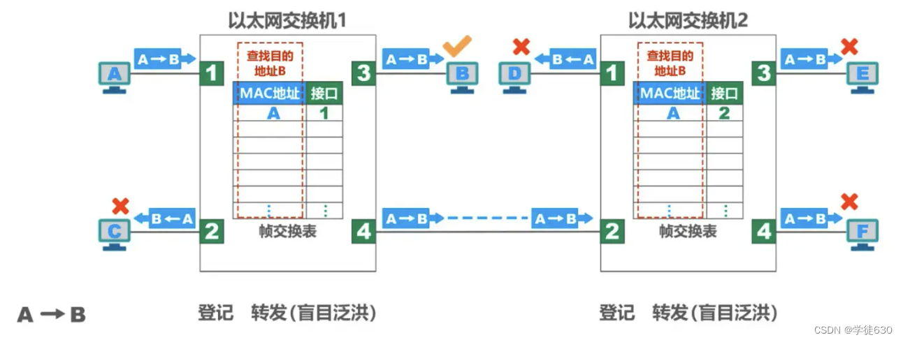
- A sends a frame to B first. The frame enters the switch from interface 1
- After the switch receives the frame, it first looks up the switching table (on the left in the figure). The interface from which this frame should be forwarded to B was not found.
- The switch writes the source address A and interface 1 of this frame into the switching table (on the left in the figure)
- The switch broadcasts this frame to all interfaces except interface 1
- From interface 4 to interface 2, first search the switching table (right in the figure). The interface from which this frame should be forwarded to B was not found.
- The switch writes the source address A and interface 1 of this frame into the switching table (right in the figure)
- If the destination address of the frame does not match the destination address other than host B, the frame will be discarded.
- Host B finds that the frame is for itself and accepts the frame.
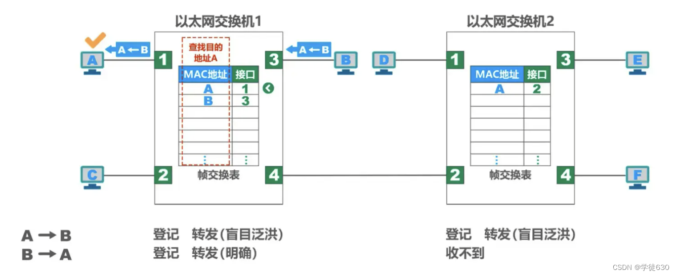
- B sends a frame to A. The frame enters the switch from interface 3
- After the switch receives the frame, it first looks up the switching table (on the left in the figure). It is found that the MAC address in the switching table (on the left side of the figure) has A, indicating that the frame to be sent to A should be forwarded from interface 1. So the frame is sent to interface 1 and forwarded to A.
- Host A finds that the destination address is it, and accepts the frame.
- The switch writes the source address B and interface 3 of this frame into the switching table (on the left in the figure)
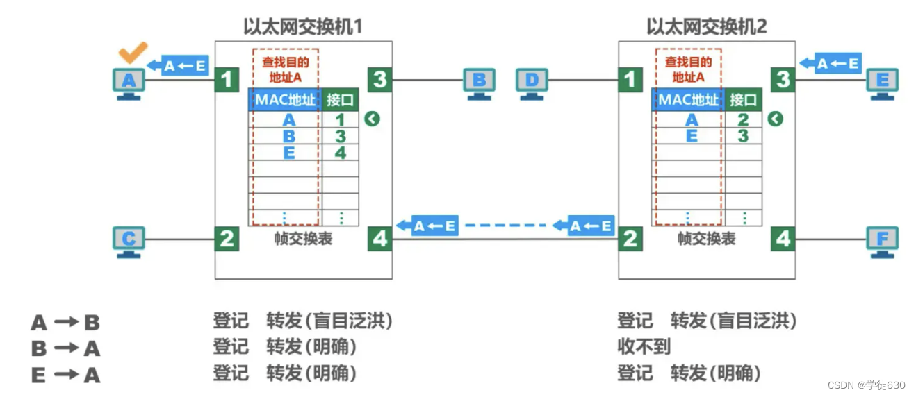
- E sends a frame to A
- After the switch receives the frame, it first looks up the switching table (right in the figure). It is found that (on the right side of the figure) the MAC address in the switching table has A, indicating that the frame to be sent to A should be forwarded out from interface 2. So the frame is sent to interface 2 and forwarded to interface 4.
- The switch writes the source address E and interface 3 of this frame into the switching table (right in the figure)
- Interface 4 goes to the switch on the left and first looks for the switching table (on the left in the figure). It is found that the MAC address in the switching table (on the left side of the figure) has A, indicating that the frame to be sent to A should be forwarded from interface 1. So the frame is sent to interface 1 and forwarded to A.
- The switch writes the source address E and interface 4 of this frame into the switching table (on the left in the figure)
- Host A finds that the destination address is it, and accepts the frame.
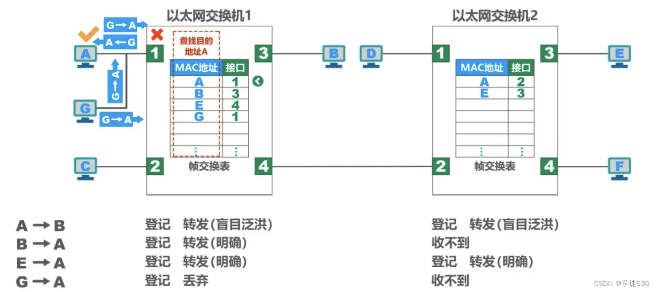
Host A, host G, and interface 1 of switch 1 share the same bus (equivalent to a bus network, which can be imagined as connected by a hub)
- Host G sends a frame to host A
- Both host A and switch interface 1 can receive
- After the network card of host A receives it, according to the destination MAC address of the frame, it knows that the frame is sent to itself, and accepts the frame.
- After receiving the frame, switch 1 first performs registration work.
- Then switch 1 forwards the frame. The MAC address of the frame is A. Find the MAC address A in the switching table (left side of the figure).
- The interface number with MAC address A is 1, but the frame enters the switch from interface 1. The switch will not forward the frame from interface 1 because it is unnecessary, so it discards the frame.
As each host in the network sends frames, each switch in the network can learn the MAC addresses of each host and their corresponding relationships with their own interfaces.

Taking into account that there may be times when a host needs to be replaced at the switch's interface, or a host needs to change its network adapter, this requires changing the items in the switching table. For this reason, each item in the exchange table has a certain validity time . Expired items are automatically deleted .
This self-learning method of Ethernet switches makes the Ethernet switches plug-and-play without manual configuration, so it is very convenient.
Summarize
Summary of steps for switch self-learning and frame forwarding


3.10. Spanning Tree Protocol STP of Ethernet switches
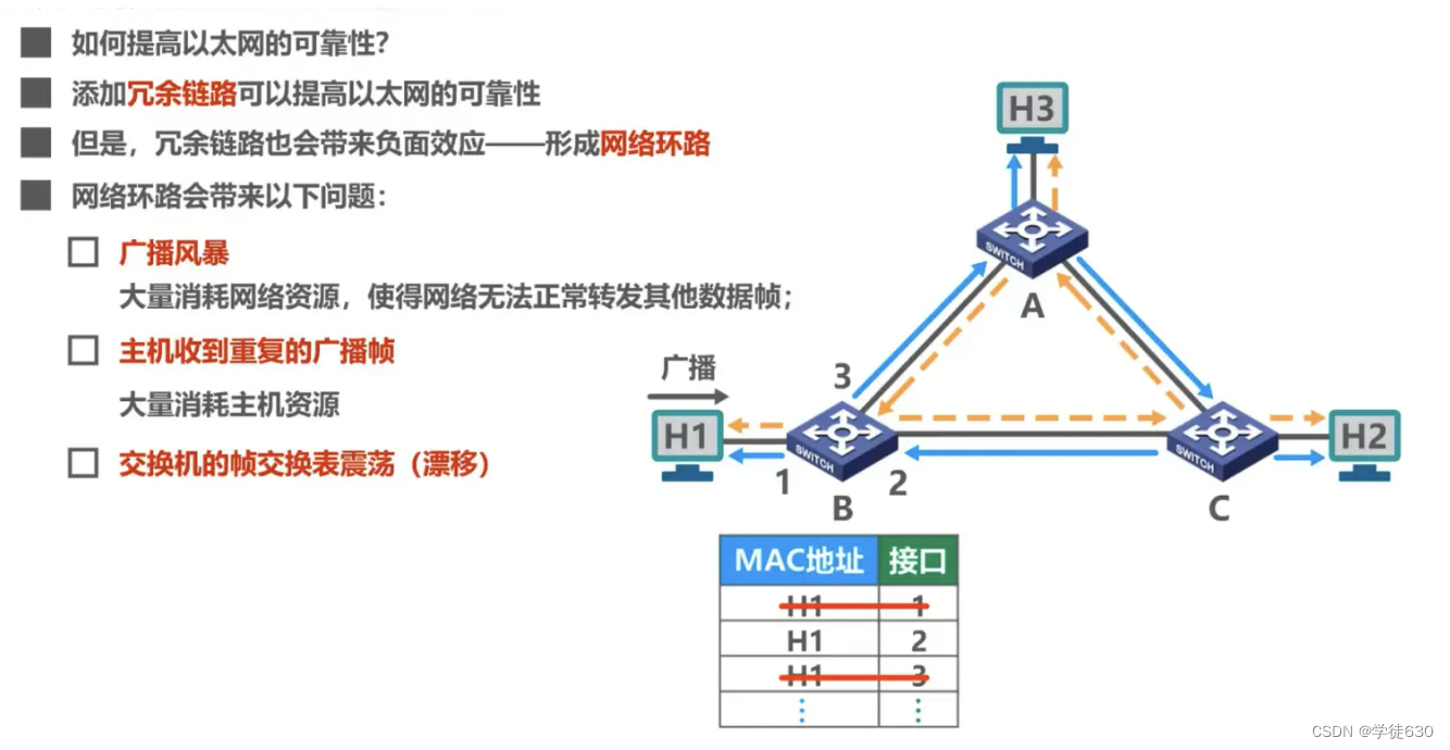
How to improve the reliability of Ethernet
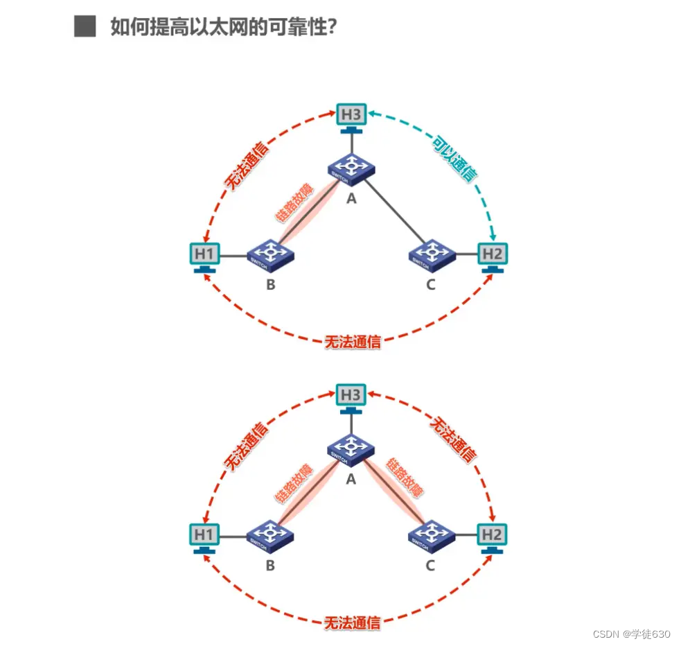

- The IEEE 802.1D standard specifies a Spanning Tree Protocol STP (Spanning Tree Protocol).
- The key point is: the actual topology of the network is not changed , but certain links are logically cut off so that the path from one host to all other hosts is a loop-free tree structure , thereby eliminating the circle phenomenon.

3.11. Virtual LAN VLAN
Why Virtual LAN VLAN
broadcast storm
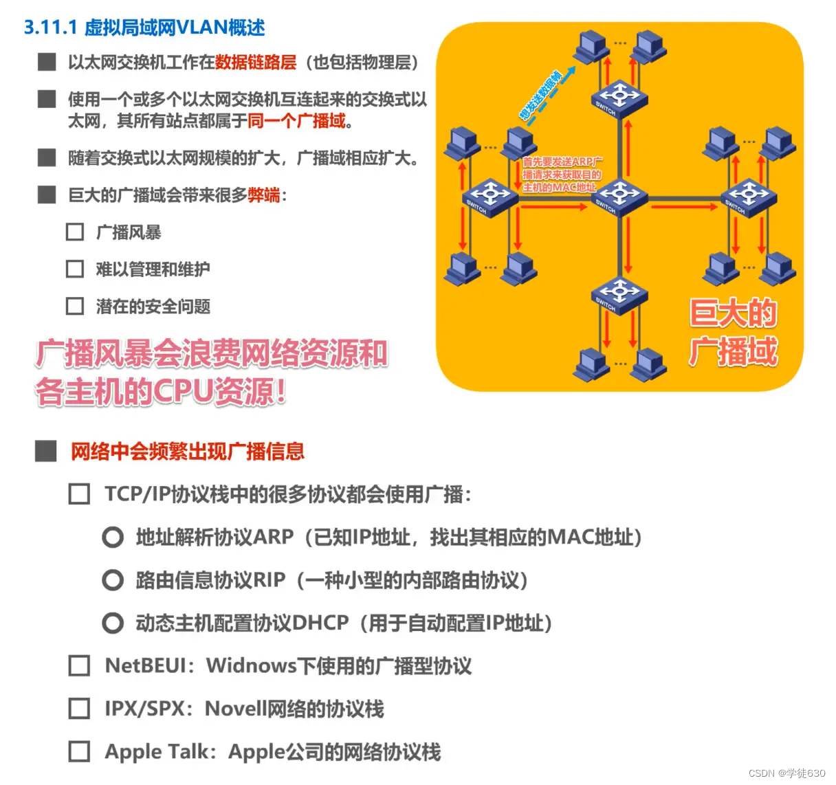
How to split broadcast domains
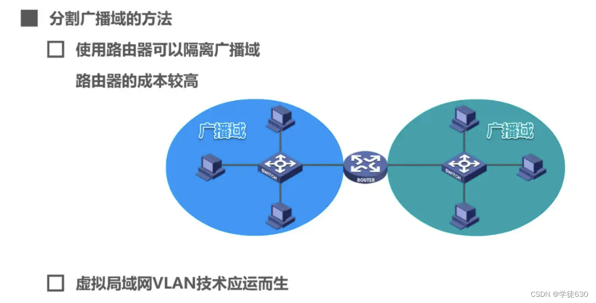
In order to divide the broadcast domain, the virtual LAN VLAN technology came into being.
concept
- Virtual LAN (Virtual LAN) can be easily implemented using Ethernet switches.
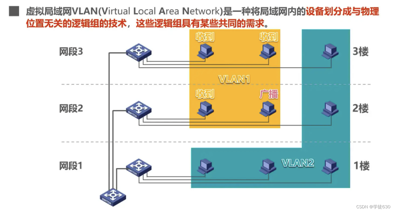
- IEEE 802.1Q definition of virtual LAN VLAN : A virtual LAN VLAN is a logical group composed of some LAN segments that has nothing to do with physical location , and these network segments have certain common requirements. Each VLAN frame has a clear identifier, indicating which VLAN the computer sending the frame belongs to.
- Broadcast communication is possible within the same VLAN, but broadcast communication is not possible in different VLANs.
- Virtual LAN is actually just a service provided by LAN to users, rather than a new type of LAN.
- Since a virtual LAN is a logical combination of users and network resources, related devices and resources can be easily regrouped as needed, allowing users to access the required resources from different servers or databases.
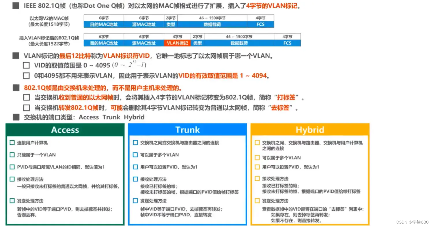
Implementation mechanism of virtual LAN VLAN
Virtual LAN VLAN technology is implemented on the switch, and the switch needs to be able to implement the following functions
-
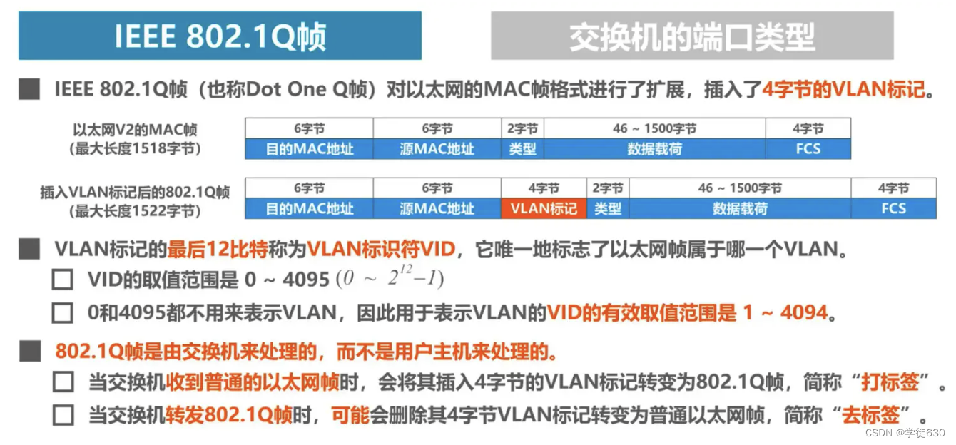
Ability to handle VLAN tagged frames - IEEE 802.1 Q frames
-
Each port of the switch can support different port types, and ports of different port types process frames differently.

Access port
Interconnection between switch and user computer
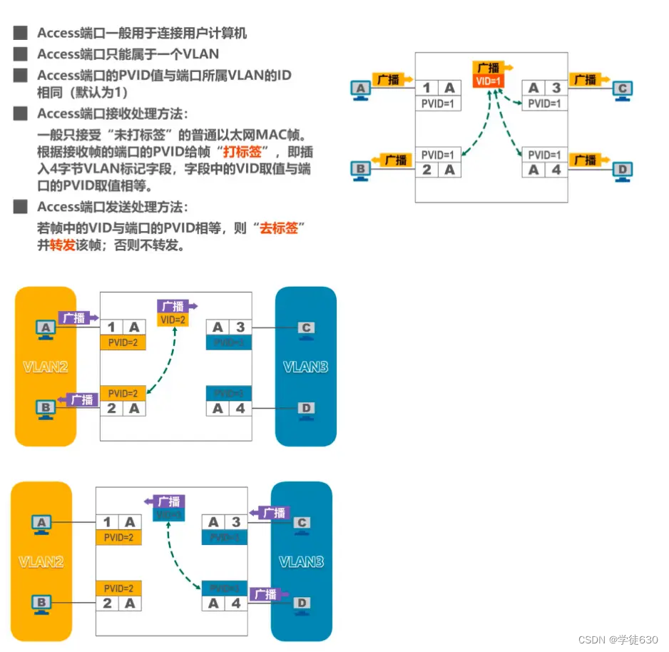
Broadcast communication is possible within the same VLAN, but broadcast communication is not possible in different VLANs.
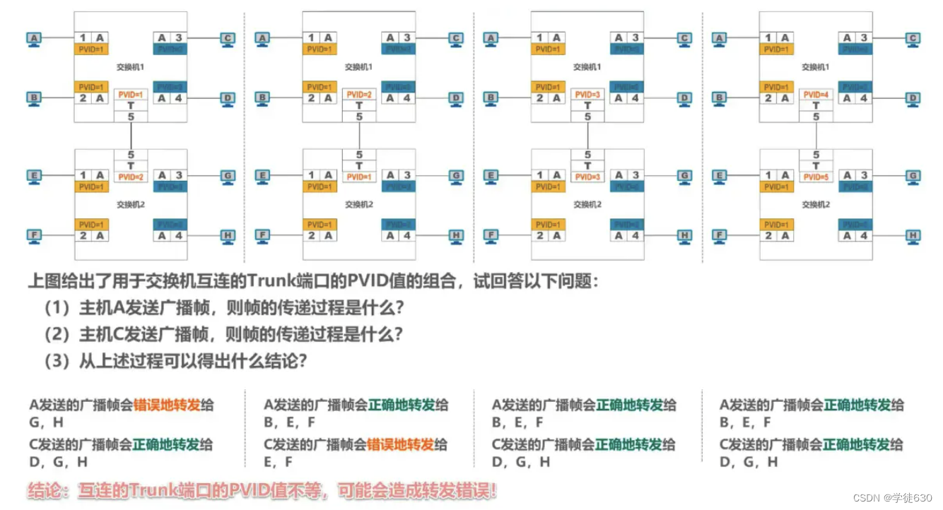
Truck port
Interconnections between switches or between switches and routers

Small examples
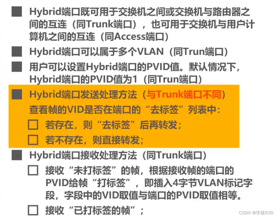
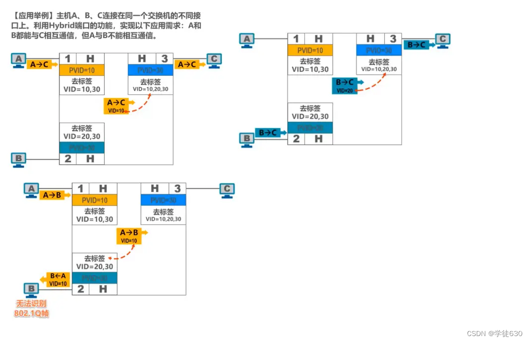
Private Hybrid port types of Huawei switches
Summarize
Advantages of Virtual LAN
Virtual LAN (VLAN) technology has the following main advantages:
- Improved performance
- Simplified management
- reduced costs
- Improved security